Manual, Robotic Electric Tool Changer, QC‑18
Document #9620‑20‑B‑18 Electric Tool Changer‑06
Pinnacle Park • 1031 Goodworth Drive •Apex, NC 27539 • Tel: 919.772.0115 • Fax: 919.772.8259 • www.ati‑ia.com
B-6
US Patent No.: 8,132,816 B2
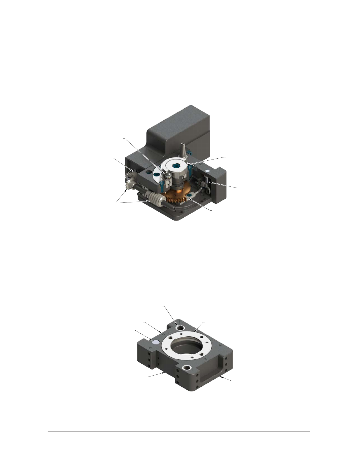
2. Installation
The Master plate assembly is attached to the robot arm and may require an interface plate to match mounting
patterns or create space to accommodate hollow wrist utilities. The Tool plate assembly is attached to the tooling
and may require an interface plate to match mounting patterns (refer to Section 8—Drawings for specific mounting
pattern details).
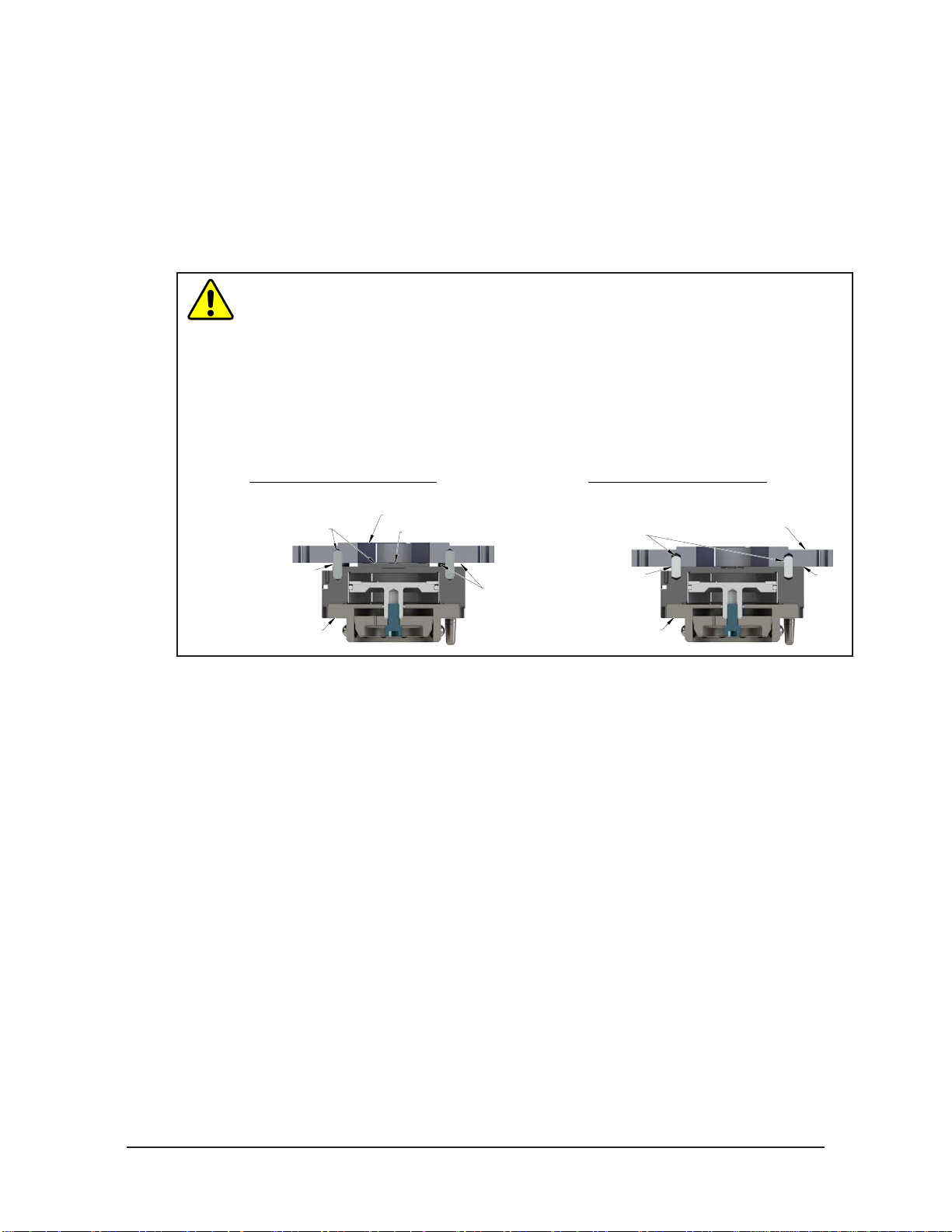
WARNING: Do not use lock washer under the head of the mounting fasteners or allow the
mounting fasteners to protrude above the mating surfaces of the Master and Tool plates.
Allowing fasteners to protrude above the mating surface will create a gap between the Master
and Tool plates and not allow the locking mechanism to fully engage, this can cause damage
to equipment or personal injury. Make sure the mounting fasteners are flush or below the
mating surfaces of the Master and Tool plates.
Head of Mounting Fastener Must Be Flush or
Below Mating Surface. (Do Not Use Lock
Washer under Head of Mounting Fastener).
Mating Surface
WARNING: Do not perform maintenance or repair(s) on the Tool Changer or modules unless
the Tool is safely supported or placed in the tool stand, all energized circuits (for example:
electrical, air, water, etc.) are turned off, pressurized connections are purged and power
is discharged from circuits in accordance with the customer specific safety practices and
policies. Injury or equipment damage can occur with the Tool not placed and energized
circuits on. Place the Tool in the tool stand, turn off and discharge all energized circuits,
purge all pressurized connections, and verify all circuits are de-energized before performing
maintenance or repair(s) on the Tool Changer or modules.
WARNING: Mounting fasteners must have a thread locker such as Loctite 242 or equivalent
applied to the threads unless they have a pre-applied thread locker. Fasteners may come
loose resulting in injury to personnel or damage to equipment. Use fasteners with pre-applied
thread locker or apply thread locker to all mounting fasteners.
CAUTION: Do not use fasteners that exceed the thread depth in the Tool Changer (refer to
Section 8—Drawings for details on mounting hole thread depth). Secure the Tool Changer
with the proper length fasteners. This is true for both robot and tool interfaces.
Table 2.1—Optional Module Fastener Size, Class, and Torque Specications
Mounting conditions Fastener Size &
Property Class Recommended
Torque Thread Locker
Optional Module or adapter plate to Master or
Tool plate, Supplied Fasteners
M3 x 0.5 Class 12.9
Pre-applied Adhesive or
Loctite 222
Socket head cap 10 in-lbs (1.13 Nm)
Socket at head cap 8 in-lbs (0.9 Nm)
M4 x 0.7 Class 12.9
Socket head cap 15 in-lbs (1.69 Nm)
Socket at head cap 10 in-lbs (1.13 Nm)