StudioComm 50 Central Controller User manual

50060-0904, Issue 6
Model 50 Central Controller,
Model 51 Control Console,
and Related Components
User Guide
Issue 6, September 2004
This User Guide is applicable for systems consisting of:
Model 50, serial number M50-00457 and later;
Model 51, serial number M51-00457 and later
© 2004 by Studio Technologies, Inc., all rights reserved
www.studio-tech.com

This page intentionally left blank.

Model 50/51 User Guide Issue 6, September 2004
Studio Technologies, Inc. Page 3
Table of Contents
Foreword ....................................................................... 5
Introduction................................................................... 7
Installation ..................................................................... 12
Advanced Installation Topics ........................................ 17
Configuration ................................................................ 19
Model 51 Configuration Chart—Main Functions...... 22
Model 51 Configuration Chart—
Alternate Functions .............................................. 23
Operation ...................................................................... 25
Troubleshooting ............................................................ 30
Technical Notes............................................................. 32
Specifications................................................................ 36
Appendix A.................................................................... 39
MIDI Messages ......................................................... 40
Block Diagrams
Model 50 Central Controller
Model 51 Control Console
Model 35/Model 38 Talent Amplifiers
Model 70 Interface

Issue 6, September 2004 Model 50/51 User Guide
Page 4 Studio Technologies, Inc.
This page intentionally left blank.

Model 50/51 User Guide Issue 6, September 2004
Studio Technologies, Inc. Page 5
Foreword
I am pleased to present the StudioComm series of products. As both president and owner
of Studio Technologies, I take a very personal approach when designing products. Get-
ting older has increased my appreciation of the more subtle things in life—be they a part of
nature or the nuances contained in a well-designed piece of electronic equipment. Do
the technical and operational aspects of a product work together to “feel” right? A Studio
Technologies’ design is ready to go only when I am completely satisfied. My entire focus
for the StudioComm series was to make a system that you’d really enjoy using, and one
that would perform reliably for years. I hope you share my enthusiasm.
Many fine people worked toward making the StudioComm “happen.” Mitch Budniak (ace
consulting engineer) designed many of the circuits. Jim Cunningham contributed to the
analog design. Larry Leviton wrote the excellent micro-controller software. Al Lux designed
the printed circuit boards. Carrie Loving designed the graphics. Fred Roeck performed the
mechanical design. Joe Urbanczyk coordinated the safety testing and agency approvals.
Many thanks to Bob Tjarks, professional audio sales manager at Gand Music & Sound,
Northfield, Illinois. Bob brought to my attention the need for a product to serve digital au-
dio workstations. His product idea evolved into the StudioComm series. Additional thanks
to Timothy Powell of Metro Mobile Recording, Glenview, Illinois, who provided his excel-
lent ears when issues of sonic quality arose. His extensive field and studio experience was
extremely helpful in keeping me on the audio “straight and narrow.”
Please contact me with your questions, comments, and suggestions. I can be reached by
Sincerely,
Gordon K. Kapes
President

Issue 6, September 2004 Model 50/51 User Guide
Page 6 Studio Technologies, Inc.
This page intentionally left blank.

Model 50/51 User Guide Issue 6, September 2004
Studio Technologies, Inc. Page 7
Introduction
What This User Guide Covers
This User Guide is designed to assist
you when installing, configuring, and
using the Model 50 Central Controller,
Model 51 Control Console, Model 35
Talent Amplifier, Model 38 Talent Amplifier,
and related components.
System Overview
The Model 50 Central Controller, along
with the companion Model 51 Control
Console, are members of the Studio-
Comm family of products. The Models 50
and 51 are specifically designed to work in
conjunction with digital audio workstations
to provide a full set of monitoring and
communications functions. Features in-
clude control room and studio monitoring,
meter output, an integrated headphone
system, dubbing, and communications
functions that include talk to studio, talk to
phones, and slate. All StudioComm func-
tions perform to a level that rivals even the
largest recording consoles. Many of the
functions are user configurable, allowing
unmatched flexibility.
The StudioComm system is designed
to provide control over monitor and dub
sources, communication from the con-
trol room to the studio, and a headphone
monitoring (cue) system. A complete
StudioComm system consists of a rack-
mounted central controller, a desktop
control console, and one or more portable
talent amplifier units.
The Model 50 Central Controller and the
Model 51 Control Console work together
to provide performance and features
for use in advanced applications. The
units interconnect using a standard 5-pin
MIDI-style cable. Circuitry in the Model
50 separately routes any of seven stereo
inputs to the control room, meter, studio,
headphone, and dub outputs, with com-
mands provided by the Model 51 Control
Console. If you have MIDI software that
supports the StudioComm system, you
can even, in lieu of the Model 51, control
the Model 50 with your computer.
The Model 51 Control Console’s built-in
microphone lets you talk to the studio or
headphone outputs. It also allows you to
talk to the dub output.
The Model 35 Talent Amplifier is a por-
table amplifier unit capable of driving one
or two pairs of high-impedance stereo
headphones. A single microphone-type
cable links the Model 35 with the Model 50
Central Controller. The Central Controller
provides power and left and right audio
over just three wires.
The Model 38 Talent Amplifier takes the
basics from the Model 35 and adds a
unique stereo preamplifier section. This
allows each Model 38 user to create an
individual headphone mix, solving the
classic problem of wanting “more me” in
the phones! Like the Model 35, the Model
38 is linked to the Model 50 Central Con-
troller by a single microphone-type cable.
System Features
Stereo Line Inputs
The Model 50 contains seven stereo line-
level inputs which are compatible with
both balanced and unbalanced signals.
Each input is independently software
configurable for a nominal input level of
–10dBV or +4dBu. This allows direct con-
nection with virtually any audio source.

Issue 6, September 2004 Model 50/51 User Guide
Page 8 Studio Technologies, Inc.
Each input can also be configured to
operate as a mono input. In this manner,
a signal connected to the left input is
routed to both the left and right outputs.
For convenience, input 7 is located on
the front panel of the Model 50; inputs 1
through 6 are located on the back panel.
Control Room Monitoring
The control room section provides two
stereo line-level outputs for driving two
power amplifiers associated with monitor
loudspeakers. Seven buttons are used to
select the input source to be monitored.
The control room level is adjusted using
a smooth-feeling rotary potentiometer. The
Dim button allows the control room level
to be temporarily reduced. The Control
Room A/B button allows the control room
A or B outputs to be activated. The Mono
button allows the sum (L+R) of the select-
ed source to be sent as the control room
output.
Meter Output
The meter output provides a stereo output
that “follows” the source selected for the
control room. The signal is not affected
by the control room level circuitry, but is
“post-mono.” The meter output is intend-
ed to be connected to VU- or PPM-type
meters or meter panels that contain series
current-limiting resistors or input buffer
amplifiers. In addition, they must support
meter calibration to ensure precision level
reading.
Meter output and
Mic Module input
Model 50 Back Panel
Model 50 Front Panel
Power present
LED
Stereo line input 7;
LED indicates +4dBu
configuration
Input data
present LED
Talent Amplifier
over current LED
Dub output;
LED indicates +4dBu
configuration
Model 51
Control Console
over current LED
Model 50
input data LED
AC mains
connection
To/from Model 51
Control Console
Output to talent
amplifiers
Control room
A & B outputs
Studio output
Mains voltage
configuration
chart
Stereo line
inputs 1-6
Dub
output

Model 50/51 User Guide Issue 6, September 2004
Studio Technologies, Inc. Page 9
Studio Monitoring
The studio monitoring source is config-
ured to follow either the selected control
room source or the headphone source.
A push button, along with an associated
LED, provides the studio on/off function.
A rotary potentiometer is used to set
the level.
Dub Output
A stereo line-level output is provided as
a dub (copy) output. Any of the seven
inputs can be assigned to the dub output.
The dub output can also be configured to
follow the source selected for the control
room output. The slate function allows
communications (voice) audio to be sent
out the dub output. For convenience, the
dub output is available from both the front
and back panels of the Model 50.
Communications Functions
The Model 51 Control Console contains
an internal microphone that is used in
conjunction with the three communica-
tions functions. The talk to studio function
interrupts the studio source and sends
communications audio. The talk to phones
function either interrupts the phones
source or adds (sums or mixes) communi-
cations audio with the phones source. The
slate function interrupts the dub source
and connects communications audio. The
slate function can be configured to send
a 50Hz sine wave along with communi-
cations audio. The audio level of each
communications function is individually
adjustable.
MIDI Control
All Model 50 Central Controller functions
are controlled using system-exclusive MIDI
messages. The Model 51 Control Con-
sole “speaks” this language, and in most
applications a Model 51 will be utilized. In
special applications the Model 50 Central
Controller can be connected directly to a
MIDI bus, allowing the creation of a fully
automated recording or audio routing
system. (For more information on MIDI
support, refer to Appendix A.)
Configuration
The Model 51 Control Console can be
configured to make the system meet a
user’s exact operating environment. As
previously discussed, each of the seven
stereo line inputs can be independently
set for –10dBV or +4dBu operating lev-
els. They also can be set for either mono
or stereo operation. In the mono mode a
signal connected to the left input is sent to
the left and right outputs. The dub output
level can be set for a nominal –10dBV or
+4dBu output level.
Unique to the system is the ability to con-
figure the dim level to one of six values,
ranging from full attenuation to a modest
10dB reduction. The auto dim off function,
when configured, allows any change in
the control room level potentiometer to
automatically turn off an active dim state.
The talk to phones function can be
configured to either interrupt the source
selected for headphone audio and con-
nect communications audio, or to have the
communications audio added (summed
or mixed) with the headphone audio.
The slate function can be configured to
generate a 50Hz sine wave when activat-
ed. This provides an audible “marker” for
analog tapes, and a visual indication on
a wave form display screen.
Four functions can be set for push-to-latch
operation if desired: talk to studio, talk to
phones, slate, and control room mono.
Issue 6, September 2004 Model 50/51 User Guide
Page 10 Studio Technologies, Inc.
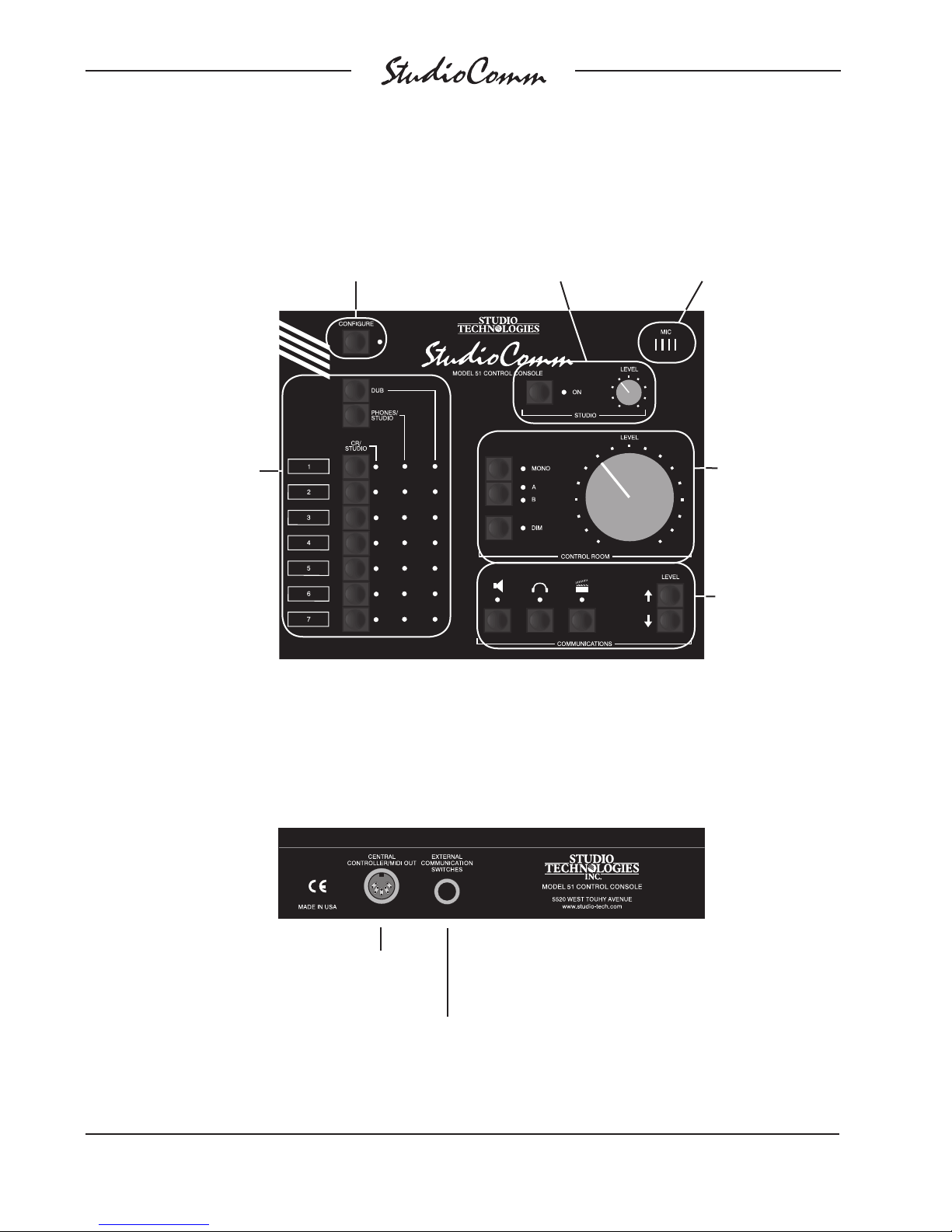
Built-in microphone for
communications
functions (talk to studio,
talk to phones, slate)
Talk to the studio or
headphones; slate; set
communications levels
Model 51 Front Panel
Studio on/off button
and level control
Configure button
switches between
normal operation
and configure mode
Change the control room
level; listen in mono
(L+R); select output A
or B; or reduce the level
by a preset amount
Source selection
for control room (CR),
studio, headphones, and
dub; three columns of
LEDs show the currently
selected sources
Model 51 Back Panel
Connection for
external talk to studio
and talk to phones
switches
Connection
to the Model 50
Central Controller

Model 50/51 User Guide Issue 6, September 2004
Studio Technologies, Inc. Page 11
The studio output is set to follow the
control room source or the headphone
source. The headphone source is set
for independent selection or to follow
the control room source. The dub source
is set for independent selection or to fol-
low the control room source.
All configuration parameters, along with
“power down” operation conditions, are
stored in nonvolatile memory.
Headphone Monitoring
The StudioComm system contains an
integrated, full-featured headphone (cue)
system. Up to four Model 35 or Model 38
Talent Amplifiers can be connected to
the Model 50’s talent amplifier output.
A single 3-conductor microphone-type
cable carries power and stereo audio.
Using the Model 51 Control Console,
any of the seven stereo inputs can be
assigned to the talent amplifier output.
The talk to phones function allows com-
munications (voice) audio to be sent to
the talent amps. The talent amplifier out-
put is short circuit protected. Error condi-
tions are displayed by the Talent Amplifier
Over Current LED on the Model 50’s front
panel.
Each Model 35 and Model 38 Talent
Amplifier can drive two sets of high-
impedance headphones (>150Ω). The
audio output is loud, and very “clean.”
The units feature a built-in level control,
a stereo/mono switch, and a power
present LED.
The Model 38 Talent Amplifier takes the
basics from the Model 35 and adds a
unique stereo preamplifier section. This
Connects to additional
talent amplifiers
Connects to the Model 50 or another talent
amplifier’s loop thru connector
Model 35 Front Panel
Model 35 Back Panel
Two headphone
outputs
Power present
LED
Headphone output
level control
Switch between
stereo and mono
(L+R) output

Issue 6, September 2004 Model 50/51 User Guide
Page 12 Studio Technologies, Inc.
Model 38 Back Panel
Connects to talent sources
such as keyboards or
microphones
Loop thru connectors parallel the
talent inputs for routing to a digital
audio workstation, effects device,
microphone preamp, etc.
Connects to the
Model 50 or another
talent amplifier’s loop
thru connector
Connects to additional
talent amplifiers
Talent level
to phones
Power present
LED
allows a musician’s microphone or line-
level signal to be “looped” through the
Model 38, boosted by its preamp, and
then combined with the stereo cue mix
supplied by the Model 50. This provides
each Model 38 with an individual head-
phone mix, solving the classic problem
of wanting “more me” in the phones!
Like the Model 35, the Model 38 is linked
with a Model 50 Central Controller by a
single cable.
Installation
In this section you will be installing the
Model 50 Central Controller in an equip-
ment rack. Audio input and output con-
nections will be made using the Model
50’s multitude of ¼-inch phone jacks.
One or more Model 35 or Model 38 Talent
Amplifiers will be connected. A location
will be selected for the Model 51 Control
Console, and it will be connected to the
Model 50. AC mains power will be con-
nected to the Model 50.
Mic/Line button switches
the talent input between
microphone and line level
Model 38 Front Panel
Switch between
stereo and mono
(L only) for the talent
input
Cue mix
level to
phones
Switch between stereo
and mono (L+R) for
the cue mix
Two headphone outputs

Model 50/51 User Guide Issue 6, September 2004
Studio Technologies, Inc. Page 13
System Components
The main StudioComm shipping carton
contains a Model 50 Central Controller,
Model 51 Control Console, 5-conductor
MIDI-style cable, and User Guide. Units
destined for North America are shipped
with an AC mains cord. Your dealer or
distributor will provide an AC mains cord
for non-North American destinations.
Model 35 and Model 38 Talent Amplifiers,
along with accessories, will be contained
in separate cartons. Please check to
ensure you have everything you need.
Mounting the Model 50
The Model 50 requires one space in a
standard 19-inch (48.3cm) equipment
rack. Select a location near where the
Model 51 Control Console will be located.
A cable is provided to connect the Model
50 to the Model 51. If required, you can
supply a longer cable, however 50 feet
(15.3m) is the recommended maximum
length. It is desirable to locate the Model
50 to allow easy access to both the front
and the back panels. The back panel
contains most of the input and output
connectors, while the front panel is used
to access line input 7 and a multiple
(mult) of the dub output. In addition, the
front panel also contains several LED
indicators. The Model 50 is secured to
the equipment rack using two mounting
screws per side.
Audio Inputs and Outputs
The Model 50’s line-level audio input and
output connections are made using
¼
-inch 3-conductor phone jacks. The
choice of phone jacks was simply a
matter of real estate—21 XLR connectors
don’t quite fit on the back of a one rack-
space unit!
Balanced Input and Output Connections
Sleeve: Shield
(Switchcraft No. 297, Neutrik NP3C, or equivalent)
Unbalanced Input and Output Connections
Sleeve: Shield
Tip: +
(Switchcraft No. 280, Neutrik NP2C, or equivalent)
Tip: +
For connection of balanced input and
output signals, ¼-inch 3-conductor phone
plugs should be used. The plugs should
be wired with tip positive (+ or hot), ring
negative (– or cold), and sleeve shield.
With unbalanced input and output signals,
either ¼-inch 2- or 3-conductor plugs
can be used. With 2-conductor plugs tip
should be wired as positive (+ or hot) and
sleeve as shield. With 3-conductor plugs
tip should be wired as positive (+ or hot)
and both ring and sleeve as shield.
Stereo Line Inputs
The Model 50 provides seven stereo
line-level inputs. Inputs 1 through 6 are
located on the back panel; input 7 is on
the front. Each input is electronically bal-
anced, and can be configured for compat-
ibility with –10dBV or +4dBu signal levels.
The Model 51 Control Console gives you
push-button control, so you can easily
change input sensitivities at any time
(refer to the Configuration section un-
der Input Sensitivity). Monaural sources
Ring: –

Issue 6, September 2004 Model 50/51 User Guide
Page 14 Studio Technologies, Inc.
should be connected to the left (L) input
and configured for mono operation (refer
to the Configuration section under Stereo/
Mono Input).
Control Room Outputs
The Model 50 contains two stereo line-
level outputs for connection to two audio
power amplifiers. These audio amps
serve two pairs of loudspeakers that are
located in the control room. (Of course
the control room outputs can be connect-
ed to loudspeakers that contain integral
power amplifiers, such as the products
from Genelec.)
The outputs, labeled A and B, are
electronically balanced and capable
of driving loads of 600 ohms or greater.
In most situations best performance will
be obtained if the audio amplifier’s input
sensitivity is set to near maximum. Refer
to the Technical Notes section for details
on setting amplifier sensitivity.
Studio Output
The Model 50 contains a stereo line-level
output for connection to an audio power
amplifier. This audio amplifier serves the
pair of loudspeakers that is located in the
studio area. (Of course the studio output
can be connected to loudspeakers that
contain integral power amplifiers.)
The output is electronically balanced
and capable of driving loads of 600
ohms or greater. In most situations best
performance will be obtained if the audio
amplifier’s input sensitivity is set to near
maximum. Refer to the Technical Notes
section for details on setting amplifier
sensitivity.
Dub Output
The Model 50 contains a stereo line-level
output which is intended for connection
to a variety of analog audio devices. The
dub output is electronically balanced
and capable of driving 600 ohm loads or
greater. With the input impedance of most
audio devices at 10k ohms or greater, the
dub output can easily drive 10 or more
devices simultaneously. The dub output
can be configured for a nominal level of
–10dBV or +4dBu, so you can connect
to all line-level inputs with no hassle (refer
to the Configuration section under Dub
Output Level).
The dub output is available on phone
jacks located on both the front and back
panels of the Model 50. The phone jacks
are connected in parallel, being a multiple
or mult of each other; one set of dub
output circuits drive both outputs. The
design intention was that permanent
connections would be made to the back
panel dub output, while the front panel
dub output would remain available for
“on the spot” use.
Meter Output
The meter output is intended for connec-
tion to VU- or PPM-style meters or meter
panels that contains input buffer circuitry
or series current-limiting resistors. The me-
ter output channels have a nominal level
of +4dBu, but are not precisely calibrated
by Model 50 circuitry. While 1%-tolerance
resistors are used in the Model 50, the
meters or meter panels should include
calibration trim pots to ensure the most
accurate level reading.
A single ¼-inch 3-conductor jack is used
to connect to the stereo meter output.
Each output channel is unbalanced, has

Model 50/51 User Guide Issue 6, September 2004
Studio Technologies, Inc. Page 15
through connector on that talent amp send-
ing the signal on to the next talent amp.
For convenience, you may want to wire
your facility to allow easy access to the
talent amplifier signal at all locations where
talent amplifiers might be used. The tal-
ent amplifiers connect to the Model 50 in
parallel, so the connectors on the distribu-
tion panels or mult boxes must be wired in
parallel.
Warning: Do not connect the Model 50’s
talent amplifier output to anything but
Studio Technologies’ talent amplifiers.
Some audio equipment may be dam-
aged by the +23Vdc contained on pin 2
of the talent amplifier output connector.
Several mounting options are available for
the Model 35 and 38 Talent Amplifiers. For
details refer to the Mounting Options sec-
tions in the Advanced Installation Topics
section of this user guide.
In special cases you may need to obtain
a stereo, balanced line level output signal
from the Model 50 talent amplifier output.
The Model 70 Interface is available for this
purpose. For details refer to the Advanced
Installation Topics section later in this guide.
Locating the Model 51 Control Console
The Model 51 was designed for desktop
use, however provision has also been
made for microphone-stand mounting.
For details refer to Mounting Options in
this section.
Connecting the Model 50 to the Model 51
A standard 5-conductor MIDI-style cable
is used to connect the Model 50 to the
Model 51; a cable is included with your
system. Just connect the cable between
Meter Output
Sleeve: Common
Tip: Left output
Ring: Right output
(Switchcraft No. 297, Neutrik NP3C, or equivalent)
a nominal level of +4dBu, and is capable
of driving loads of 2k ohms and greater. A
¼-inch 3-conductor plug should be wired
with tip for the left output, ring for the right
output, and sleeve for common.
Mic Module Input
A ¼
-inch 3-conductor phone jack, labeled
Mic Module, is located on the back panel.
In most cases the Mic Module input will
not be used, and no plug should be insert-
ed. For details on using the Mic Module
input, refer to the Advanced Installation
Topics section later in this guide.
Talent Amplifier Output
Up to four Model 35 or Model 38 Talent
Amplifiers can be connected in any com-
bination to the Model 50’s talent amplifier
output. The output connector is a 3-pin
male XLR-type. For best performance, use
low-capacitance shielded microphone-
type cable to distribute the talent amplifier
signal. If you have a choice, select cables
with the heaviest wire gauge commonly
available. This will reduce voltage drop
when using long cable runs. Refer to the
Technical Notes section for additional
information.
The simplest installation would use a
microphone cable to connect the Model
50 to the first talent amplifier; the loop

Issue 6, September 2004 Model 50/51 User Guide
Page 16 Studio Technologies, Inc.
the female 5-pin DIN-type connectors
on the back of the Model 50 and 51,
and you’re done.
Note: If you require a longer cable, be
certain to buy a MIDI cable that has all five
pins wired. If they aren’t all connected, the
Model 51 will not operate. This is because
the Model 50 powers the Model 51 with
the pins that aren’t used for MIDI data.
For best performance, the cable that
connects the Model 50 with the Model
51 should be limited to 50 feet (15.3m).
Should you need to exceed this length,
refer to the Technical Notes section
of this guide for details on the cable
requirements.
For more information on MIDI, and using
controllers other than the Model 51,
please refer to Appendix A.
Remote Control Inputs
The Model 51 allows the connection of
two external switches or contact closures.
Refer to the Advanced Installation Topics
section of this guide for details.
AC Mains Power
The Model 50 is internally configured to
operate from either 100, 120, or 220/240V,
50/60Hz. In most cases, units shipped
to North America are factory selected for
120V operation. Units bound for Japan are
selected for 100V, while our friends “down
under” and in Europe receive units set for
220/240V. Before connecting the Model
50 to mains power, check that it is con-
figured to match the local mains voltage.
Look on the back panel, adjacent to the
power entry connector, for the configured
voltage(s). Note than an incorrect configu-
ration could seriously damage the unit.
Should it be necessary to change
the unit’s operating voltage it must be
performed only at the factory or by
an authorized service technician.
The Model 50 uses an IEC standard
connector to mate with the AC mains
cord. The wire colors in the AC mains
cord should conform to the internationally
recognized CEE color code and must
be wired accordingly:
Connection Wire Color
Neutral (N) Light Blue
Line (L) Brown
Protective Earth (E) Green/Yellow
Safety Warning: The Model 50 does
not contain an AC mains disconnect
switch. As such the mains cord plug
serves as the disconnection device.
Safety consideration requires that
the plug and associated outlet be
easily accessible to allow rapid discon-
nection of mains power should it prove
necessary.
As soon as mains power is applied, the
Model 50’s power present LED will light.
The Model 51 will go through its power-
up sequence lighting each LED in a rapid
sequence. The power present LEDs on
the talent amplifiers will also light.
The two Over Current LEDs located on
the front panel of the Model 50 should not
be lit. If either or both are flashing, imme-
diately refer to the Troubleshooting section
of this guide. If everything appears to be
functioning properly you are now ready to
configure the system.

Model 50/51 User Guide Issue 6, September 2004
Studio Technologies, Inc. Page 17
Advanced
Installation Topics
Model 35 Stand Mounting
Included with each Model 35 Talent
Amplifier is a nifty mounting adapter that
allows the unit to be conveniently attached
to a microphone stand. Please refer to the
Installation Guide provided in the Model
35’s shipping carton for details.
Model 38 and Model 51 Mounting
Options
The Model 38 Talent Amplifier and the
Model 51 Control Console include provi-
sions for mounting to microphone stands,
equipment consoles, etc. To avoid
“reinventing the wheel,” our products are
compatible with the 25 Series components
from OmniMount Systems, a supplier of
finely engineered mounting systems. This
firm makes many versions of the 25 Series;
one of which should fit your needs. If you
desire microphone stand mounting the fol-
lowing components would be appro-priate
for English-thread applications: 25RST-25H
Straight Tube Reverse Mount with Quick
Release, along with a 25MA Microphone
Stand Adapter. (If quick adjustment is not
required the 25RST Straight Tube Reverse
Mount can be used in place of the first
item.) When connecting to metric-thread
stands please contact OmniMount
for the correct part numbers.
The bottom surface of the Model 38 Talent
Amplifier contains two threaded inserts
that will accept English-standard ¼
-20
screws. Using two, 5/8-inch long, round-
head machine screws, the 25 Series clamp
assembly can be directly attached. The
cover of the Model 38 does not have to
be removed.
The design of the Model 51 did not allow
the inclusion of threaded inserts, so holes
of adequate size to allow ¼
-20 round head
machine screws are provided. It is intend-
ed that screws of 5/8-inch length, along
with lock washers and machine nuts, will
securely attach a 25 Series mounting
clamp assembly. The cover of the Model
51 will have to be removed to gain ac-
cess to mounting holes. Be careful when
selecting the mounting screws—exceed-
ing the recommended 5/8-inch length will
cause the mounting screws to damage the
Model 51’s internal components.
Remote Control Inputs
The Model 51 allows you to connect two
external switches or contact closures to
enable system functions. Input 1 allows
either a remote talk to studio or a remote
control room source select function to be
implemented. Input 2 allows a remote talk
to phones function to be implemented.
Using the remote “talk to” functions, it may
be useful to install switches at a producer
or director location. The Model 51 con-
tinues to provide local talk to studio and
talk to phones access even when external
switches are connected.
The required connector is a ¼
-inch
3-conductor phone plug. Tip is talk to
studio or control room source select, ring
is talk to phones, and sleeve is common.
External Communications Switches
Sleeve: Ground
Tip: Talk to studio
Ring: Talk to phones
(Switchcraft No. 297, Neutrik NP3C, or equivalent)

Issue 6, September 2004 Model 50/51 User Guide
Page 18 Studio Technologies, Inc.
Switchcraft No. 297, Neutrik NP3C, or
equivalent will work correctly. Use a mo-
mentary, single-pole, single-throw switch
for each remote function. The respective
function is activated when the tip or ring
get shorted to the sleeve.
While the Model 51’s talk to studio and
talk to phones buttons can be configured
to latch, the remote control inputs are
always push to activate. This is provided
as a safety feature preventing an external
user from “latching” one of the functions
to the on state.
Mic Module Input
The Model 51 Control Console contains
a microphone which provides the audio
source for the Model 50’s communica-
tions functions. In special applications the
Model 51 may not be used, and a sepa-
rate source of communications audio will
be necessary. The Mic Module input on
the back panel of the Model 50 allows this
to be easily accomplished.
Even if you are using the Model 51 Con-
trol Console you may want to provide an
alternate source of communications audio.
To use your own microphone and preamp,
directly connect it using the Mic Module
input jack. The Mic Module input is a
¼
-inch 3-conductor phone jack with
+12Vdc on tip, audio input on ring, and
ground on sleeve. The audio input re-
quires a nominal –10dBu signal (–10dBu,
not –10dBV!). The +12Vdc on the tip is
from the same source that powers the
Model 51, and is provided to power an
external preamp. If you feel the urge to
use this power source, be aware that it
only provides 110 milliamps of current of
which the Model 51 needs about 100mA.
So go ahead and use all the current you
need, as long as it doesn’t exceed 10mA!
Note: Communications audio from the
Model 51 is routed into the Model 50’s
circuitry through the normal connection
on the ring contact of the Mic Module
input jack. When a phone plug is inserted
into the Mic Module input, the audio path
from the Model 51 to the Model 50 is bro-
ken. This means you can’t use the Model
51’s microphone and the Mic Module
input at the same time.
Model 70 Interface
In most cases Model 35 and/or Model 38
Talents Amplifiers will be used to drive
headphones associated with a Studio-
Comm installation. In special cases a line
level signal may be required to interface
the Model 50 Central Controller’s talent
amplifier output with other audio equip-
ment. An example would be to use the
Model 50 with an existing headphone
system. The Model 70 Interface is used
to convert the talent amplifier signal to
a stereo, balanced line level signal.
Installation is very simple. Connect the
Model 70 to the Model 50 Central Con-
troller’s talent amplifier output using a
standard 3-conductor microphone-type
cable. For best performance, use low-
capacitance shielded cable.
Tip: +12Vdc
Sleeve: Ground
Mic Module Input
Ring: Communications
Audio Input
(Switchcraft No. 297, Neutrik NP3C, or equivalent)

Model 50/51 User Guide Issue 6, September 2004
Studio Technologies, Inc. Page 19
Model 70 Front Panel
Model 70 Back Panel
The Model 70 provides independent
left and right balanced outputs. Pin 1 is
shield, pin 2 is signal positive (+ or hot),
and pin 3 is signal negative (– or cold).
The electronically balanced outputs
have a nominal signal level of +4dBu
and are capable of driving loads of 600
ohms or greater.
The Model 70 can be used by itself, or
in conjunction with up to four Model 35
or Model 38 Talent Amplifiers. The loop
through connector on the Model 70 can
be used to connect to a Model 35 or 38
Talent Amplifier.
Configuration
Many StudioComm functions can be con-
figured to meet the exact needs of your
installation. Here’s an overview of what
you can configure:
• –10dBV or +4dBu level for each input
• Stereo or mono for each input
• –10dBV or +4dBu level for the dub
output
• Dim level
• Auto dim off function
• Studio source follows control room or
headphone source

Issue 6, September 2004 Model 50/51 User Guide
Page 20 Studio Technologies, Inc.
• Headphone source is independently
selected or follows control room source
• Momentary or latching operation for
mono, talk to studio, talk to phones,
and slate buttons
• Talk to phones interrupts or adds to
phones source
• 50Hz slate tone on or off
• Dub source is independently selected
or follows control room source
• Remote control room source select
parameters
• Level control auto mute
The Configure button allows the Model 51
to go into the configure mode. While in the
configure mode, all the Model 51’s buttons
and LEDs are associated with configure
functions. Refer to the Model 51 Configura-
tion Chart later in this section.
To enter the configure mode, press and
hold the Configure button for two seconds.
While in the configure mode, all audio out-
puts switch off and the orange LED beside
the Configure button will flash. As you make
changes, the Model 51 keeps track of the
new settings and updates the system when
you exit the configure mode. You must exit
the configure mode before any changes
take effect.
Input Sensitivity
The CR/Studio column of seven red LEDs
shows you whether an input is set to be
compatible with –10dBV or +4dBu signal
levels. When a red LED in the CR/Studio
column is off, it means the input is set to
–10dBV. When lit, the corresponding input
is set to +4dBu. Just press the CR/Studio
buttons to toggle inputs 1 through 7
between –10dBV and +4dBu.
For convenience, Input 7 is located on
the front panel of the Model 50. It has
a green LED beside it labeled +4 Input
Level. When lit, it tells you that Input 7 is
set for +4dBu. This means each time you
connect a new signal to Input 7, you don’t
have to go into the configure mode to
determine the input sensitivity. You should
note, however, that configure settings
aren’t updated until you leave the con-
figure mode, so the +4 Input Level LED
won’t reflect a change until you exit.
Stereo/Mono Input
The Phones/Studio column of seven green
LEDs indicates whether an input is config-
ured for mono or stereo operation. When
an LED in this column is off, the input is
set for stereo; the LED on means the cor-
responding input is set for mono. In mono
mode, the left input is sent out both the
left and right outputs. To toggle a channel
between stereo and mono, press and hold
the Phones/Studio button and press the
CR/Studio buttons that correspond to in-
puts 1 through 7. After you leave the con-
figure mode, inputs configured for a mono
source will flash during normal operation.
Dub Output Level
The Dub column of orange LEDs will help
you configure two options: dub output
level and dim level. The orange LED in
the first row (number 1 at the top) tells you
whether the dub output is set to –10dBV
or +4dBu. When the LED is off, the dub
output is set to –10dBV; when it’s on, the
dub output is configured for +4dBu. The
dub output on the front panel is in parallel
with the dub output on the back panel, so
one configure setting controls both. For
convenience, a green LED on the front
panel is provided that lights when the dub
output level is set to +4dBu. This means
This manual suits for next models
3
Table of contents


