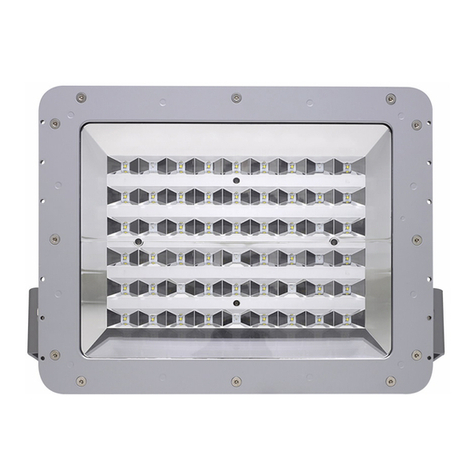
STUDIODUE Hercules 800E User manual

User’s and operator’s manual for art. 0305
PROVISIONAL

1
Safety informations........................................................................................................................... page 2
Technical features.............................................................................................................................. page 3
Before using....................................................................................................................................... page 4
Lamp installation, replacement and setting.................................................................................... page 5
Beam angle setting ........................................................................................................................... page 6
Control panel .................................................................................................................................... page 8
Control panel configuration and fixture management .................................................................... page 9
ENGLISH INDEX

2
INTRODUCTION
Thank you for choosing the Hercules800e !
TheHercules800e projects,thanksto anextremely efficientoptic system(PATENTPENDING),a powerfullight beamwhich cancreate
numberless color shades. Its performances, in terms of luminousity and lighted surfaces, can reach incredible levels.
New concept optical system (WxH 40°x45° or 45°x40°) with rotating parabole to illuminate the surface with maximum horizontal or
vertical beam opening
The Hercules800e comes in unique version:
• Art. 0305 HERCULES 800E
The Hercules800e can work in automatic mode or in synchro mode, otherwise may be controlled by 8 bit DMX controllers
The input protocol is the DMX 512. To drive the Hercules800e we suggest to use either our controller Control Show 512, Fancy or
the Easy Control.
To make the most of its possibilites and for a correct functioning of this unit in the years to come, we suggest you to read carefully
this manual before connecting or putting the spot into use. By doing so you will gain experience with its commands and connections
and you will be easily able to use it.
WARNING
!SAFETY INFORMATION
READ ALL CAUTIONS AND WARNINGS PRIOR TO OPERATE THIS EQUIPMENT.
INSTRUCTION TO PREVENT INJURY OR DAMAGE DUE TO ELECTRIC SHOCK, FIRE, MECHANICAL HAZARDS AND
UV RADIATION HAZARDS.
• PROTECTION AGAINTS FIRE
1) This equipment is designed for use with the following lamps only: BA 800SE, MSD 575HR.
Other available lamps: HMP 575SE, MSA 600SE, MSR 575HR.
DO NOT USE ANY OTHER TYPE LAMP!
2) Maintain minimum distance of 0.5 meter from walls or any other type flammable surfaces.
3) Maintain minimum distance to lighted objects of 5.0 meter.
4) Replace fuses only with the specified type and rating.
5) Do not install the spot close to heat sources. Do not lay the connection cable on the spot when it is warm.
• PROTECTION AGAINST ELECTRIC SHOCK
1) This equipment must be earthed.
2) Class I equipment. The power supply cord includes a protective earthing conductor as part of the cord.
3) For connection to the mains supply proceed as page 4. The equipment must be connected to branch circuit having a
circuit- breacker In=10A Id=0.03A (230VAC)
4) Disconnect power before lamp’s replacement or servicing (service personnel).
• PROTECTION AGAINST MECHANICAL HAZARDS
1) Use secondary safety chain when fixing this equipment.
2) Hot lamp explosion hazard. Do not open the equipment for 600 seconds after switching off.
3) Equipment surface may reach temperature up to 100°C. Allow about five minutes before handling.
4) Replace the lamp if it is damaged or thermally deformed.
• PROTECTION AGAINST UV RADIATION HAZARDS
1) Do not start on this equipment without lamp enclosure or if the protection screens, or ultraviolets screens are damaged.
2) The protection screens, the lenses, or the ultraviolet filters must be replaced if they are visibly damaged and their effectiveness
has been reduced, for example, by cracks or deep scratches.
3) Do not look directly at the lamp while lamp is on.
YOUR REFERENCE
Always remember to give the serial number and to specify the model any time you address the seller for information or assistan-
ce.
BASIC KIT
The basic kit of the Hercules800e flood projector consist of:
•Projector
•User’s manual
•Power connector
•Studio Due warranty
Available on request:
•Lamp

3
TECHNICAL FEATURES
•LAMPS
•OPTIC COLOUR SYSTEM
Full CYM unlimited variety of colours and shades + 2 colours (red and pink)
Color filter corrector (from 6500°K to 3200°K)
High resolution stepper motors
•BEAM ANGLE
Beam angle (50%): WxH 40°x45° or 45°x40°
New concept optical system with rotating parabole to illuminate the surface with maximum horizontal or vertical beam opening
Motorised variation of the beam opening
•SETUP AND CONFIGURATION
Control panel with graphic LCD display and smart reading by DMX start address by a triple led display
Easy and intuitive program and setup by a dynamic menu and four buttons
Real time monitor and full control of lamp power and all electronic ballast parameters
Stand-alone control: auto mode function master/slave (syncro mode) with 5 non editable standard programs and 4 programmes
for customization by the user
Built-in REAL TIME CLOCK for synchronised auto switch-on/off which is operated on a weekly timer (weekly schedule)
•CONTROL INPUT
Standard interface: RS-485; opto-couplet input
Protocol: USITT DMX 512
•DMX CHANNELS
1=motor speed
2=pink
3=red
4=filter corrector
5=yellow
6=cyan
•POWER SUPPLY
Rated voltage: 95-265V 47-63Hz (Electronic Ballast)
Fuses: 2x8A
Rated power: 1000Va
Rated current: 4.5A (230V) - 9A (117V)
•POWER FACTOR CORRECTOR: built-in cos Ø 0.99
•IP RATE = IP 66
•DIMENSIONS (wxdxh): mm 650x610x740
•WEIGHT: Kgs. 62,0
Check that the fixture has not been damaged during transport. If it has been damaged or it does not work,
address the seller. Whether the fixture has been shipped to you directly, please contact the shipping company.
Only the consignee (person or company) can claim for these damages.
WARNING
!
Lamps BA 800 SE MSD 575 HR Available lamps
Colour temperature 5.600° K 6.000° K HMP 575 SE
Lamp life 1.000 hours 3.000 hours MSR 575 HR
Luminous flux 65.000 lm 43.000 lm MSA 600 SE
Colour rendering index (Ra) > 90 (Ra) > 90
Burning position universal universal
7=magenta
8=dimmer
9=aux
10=beam angle
11=remote reset- lamp on/off

4
BEFORE USING
Read all cautions and warnings to page 2 prior to install this equipment. Particularly, read the follow:
1) Disconnect power before lamp’s replacement or servicing (service personnel)
2) Do not open the lamp cover for 300 seconds after switching off
3) Wear gloves and goggles to re-lamping or to work inside the unit (service personnel)
Before connecting the equipment to the power system: make sure that the mains voltage and frequency correspond to rated
values.
• The fixture is equipped for a mains voltage 95-265VAC, 47-63Hz.
The power supply cords construction is shown in pict.1. For connection to the mains supply proceed as pict.1.
The equipment must be connected to branch circuit having a circuit-breacker In=10A • Id=0.03A (230VAC)
a) Do not install the spot close to the heat sources. Observe minimum distance between the fixtures of 1.5 meters. Do not lay the
connection cable on the spot when it is warm.
b) This unit must be positioned as to allow its ventilation.
c) The unit must be positioned at least 50 cm. from walls or other flammable surfaces.
d) Observe minimum distance to lighted objects of 5 meters.
External surface temperature Ta 35°C:
• After 10 minutes work; Tc=75°C.
• Once the thermic balance has been obtained; Tc=100°C.
4) The protection screens, the lenses, or the ultraviolet filters must be replaced if they are visibly damaged and their effectiveness
has been reduced, for example, by cracks or deep scratches.
5) The lamp must be replaced if it has been damaged or thermally deformed.
6) Do not handle the spot by taking it by the head, but always by using the special handles.
WARNING
!
pict.1
INPUT CONNECTOR IP 68 3 PIN CONNECTOR FOR DMX LINE
CIRCUIT - BREAKER
MAINS VOLTAGE In Id
230V 10A 0,03A
CONDUCTOR SIZES (length < 20mt.)
MAINS VOLTAGE CROSS SELECTIONAL AREAS
230V 3X1,5 mm2(minimum)
110V 3x2,5 mm2(minimum)
The equipment must be earthed. If this rule is not followed, the warranty will be void.
N = NEUTRAL
L = LIVE
= EARTH
pict.2

5
1) Disconnect power before lamp’s replacement or servicing (service personnel)
2) Do not open the lamp cover (G) for 600 seconds after switching off
3) Wear gloves and goggles to re-lamping or to work inside the unit (service personnel).
4) Loosen the two screws (B), unscrews completely the two screws (A) and open the lamp cover (G), pict.3
5) Unscrews the two screws (C) on the lamp support plate, pict.4
6) Remove the lamp holder (D) and insert the lamp into the lampholder, pict.5
Do not touch the quarz bulb with fingers. If this happenes, clean the bulb before use with dry cloth and alcohol.
7) Replace, with care, the lampholder (D) and screws the two screws (C).
In case of replacement of the lamp or maintenance, do not open the fixture unless 10 minutes have passed from
the switching off.
This operation has to be done when the fixture is disconnected from the mains supply
WARNING
!
C
pict.3
A
G
B
C
pict.4
pict.5 D
LAMP'S INSTALLATION/REPLACEMENT

6
BEAM ANGLE SETTING (default 45°x40° or 40°x45°)
The fixture, thanks to the new concept optical system with rotating parabole (WxD 45°x40° or 40°x45°), allows to illuminate the
surfaces with maximum horizontal or vertical beam opening.
Operate as shown in the pictures below to set the vertical or horizontal parabole position (default position is 45°x40°).
pict.5a
1) Unscrews the six screws (S) on the head cover and remove it, pict 5
2) Loosen the two pommels (P) under the dicrhoic group (I), pict.5a
3) Rotate (clockwise) of 45° the parabole up to stop it, pict.6 and 6a
4) Screws the two pommels (P), pict.6a
5) Open the four spring lock (S) on the four side of the dicrhoic group (I),
pict.7
6) Lift and rotate the dicrhoic group (counter-clockwise) and reposition it
on the four cylindrical pin (L).
7) Close the four spring lock (S) on the four side of the dicrhoic group (I),
pict.7
P
P
I
P
P
pict.6 pict.6a
P
P
S
pict.7
L
I
S
S
pict.5
M
HORIZONTAL BEAM ANGLE 45°X40° (WxH) VERTICAL BEAM ANGLE 40°X45° (WxH)

7
To completely remove the dichroic unit (I) operate as shown in the pictures below
1) Cut the two clamps (N)
2) Open the spring lock (S)
3) Unscrew the four screws (Q)
4) Remove the wire protection (U)
5) Open the other three spring lock (S) on the three side of the dichroic unit (I)
6) Unscrew and remove the wire protection (V)
7) Disconnect the connecter (Z) and remove the dichroic unit (I)
8) Put again the two clamps (N) once the dichroic unit installation has been made
NI
SQ
VZ
screw
pict.8
pict.9

8
icon
UTILITY
DMX Rd / Wr >
Programs >
Advanced >
___ Hercules ___
Version 1.00
Serial 10001
DMX001 Next 012
Lamp STRK - 5
TUE 15 : 35
Press any key
THE CONTROL PANEL
Here below you can see the control panel major screen.
001
icon
Select
a menu
and
press OK
ADDRESS...
+
-
O
k
E
s
c
Address
DMX Ch 001
Next Ch 012
Channels 11
O
k
E
s
c
icon
Select
a menu
and
press OK
UTILITY >
O
k
E
s
c
O
k
E
s
c
pict.10
Choosed menu
Choosed menu
This icon (>) shown that is possible to
enter in another sub-menu
Choosed menu
4 interactive navigation buttons.
The function of the button is indicated on
the display (to the right and to the left) by
specific labels placed in correspondence
of the buttons
Sub-menus
This icon (...) shown that is possible
directly to insert the values
Choosed menu
change the values
EXAMPLE 1: (...) ICON
EXAMPLE 2: (>) ICON
12
12
icon
UTILITY
Programs
Master Auto >
Define...
User >
O
k
E
s
c
Choosed menu
Sub-menus tree
Sub-menus
3
icon
UTILITY
Programs
Mode
DMX
Master Auto
Master Man
Slave
O
k
E
s
c
Choosed menu Sub-menus tree
Sub-menus
4
This icon (>) shown that is possible
to enter in another sub-menu.
For example you select and choose
Programs > with the 2 navigation
buttons on the right and press OK
This icon (...) shown that is possible
directly to insert the values
This icon (>) shown that is possible
to enter in another sub-menu. For
example you choose Master Auto >
and press OK
4 interactive navigation buttons.
The function of the button is indicated on the display
(to the right and to the left) by specific labels placed in
correspondence of the buttons

9
CONFIGURATION AND SETUP
The equipment can works as follows:
- DMX MODE: driving by controller DMX
- STAND ALONE: manual working/automatic by the small panel at machine-border. In this case the item can manage others
Hercules connected to the same DMX line and checking the switching On and Off at times, arranged by an internal clock at week-
planning.
MANAGEMENT OF EQUIPMENT BY DMX SIGNAL
The DMX channel interested in Hercules 800 are 11. Excluding the reset remote function and lamp Off remote, the channel be-
came 10.
CH1 MOTOR SPEED
CH 2 COLOUR 1
CH 3 COLOUR 2
CH 4 COLOUR 3
CH 5 COLOUR 4
CH 6 COLOUR 5
CH 7 COLOUR 6
CH 8 DIMMER
CH 9 AUX
CH 10 FOCUS
CH 11 RESET/SWITCHING OFF LAMP
Motor speed (8 levels): value 0…31 speed 1 (min), 32…63 speed 2, 64…95 speed 3, 96…127 speed 4, 128…159 speed 5, 160…
191 speed 6, 192…223 speed 7, 224…255 speed 8 (MAX).
COLOUR 1 (progressive 256 levels): value 0…255
COLOUR 2 (progressive 256 levels): value 0…255
COLOUR 3 (progressive 256 levels): value 0…255
COLOUR 4 (progressive 256 levels): value 0…255
COLOUR 5 (progressive 256 levels): value 0…255
COLOUR 6 (progressive 256 levels): value 0…255
DIMMER (progressive 256 levels): value 0…255
FOCUS (progressive 256 levels): value 0…255
RESET/lamp SWITCHING OFF: value 0…127 no operation, 128…191 motor reset, 192…239 no operation, 240…250 lamp turning
off,251…255 no operation.
ON BOARD CONTROL PANEL BASIC WORKING
By this panel you can set up the equipment for the best working.
By an internal memory it is possible to set up user programs allowing the working even without DMX controller.
In order to simplify the utilization and the configuration, the 4 buttons, placed on the external sides of the graphic display, take
different function according to the parameter we have to modify. The function of the button is indicated on the display by specific
labels placed in correspondence of the buttons.
All the function parameters are shown in the main screen, such as: (see pict.10 page 8)
Version XXX
Serial XXX
DMX XXX
Next XXX
Lamp status
Weekly hour and day
To enter the menu list you can push any button.
For each menu you can find another sub-menu.
In every menu and sub-menu you can find the button ESC, which allow, by pushing it, to go from an sub-menu to an external
menu, up to the main screen.
MENU LIST (8 main menu)
ADDRESS (inserting first DMX channel used by the Hercules)
DIMM/SHUTT
> DIMMER
MOD1 (CH8=0 closed dimmer, CH4=255 opened dimmer)
MOD2 (CH8=255 closed dimmer, CH4=0 opened dimmer)
> ADVANCED
TIME OUT (unable/disable shutter closing without DMX signal)

10
TIME… (fix the time between no signal DMX and shutter closing)
HRS COUNT
> LAMP XXXX (lamp life)
> FIXTURE XXXX (fixture life)
DISPLAY
FLIP
YES (for overturn the display visual)
NO
> ADVANCED
AUTO SHUT
YES (To permit the automatically turning off of display within 30 seconds)
NO
BRIGHTNESS (to fix the display brightness)
UTILITY
> DMX Rd/Wr
PARAMETERS (to visualize enter DMX signals)
READ (to visualize the DMX channel value on line)
WRITE (bypass DMX signal in entry and direct parameters passing)
> PROGRAMS
- MODE
DMX (DMX function by external controller DMX signal)
MASTER AUTO (automatic function with timer switching)
MASTER MAN (automatic function. No timer)
SLAVE
> DEFINE
> USER
EDIT U1 (modify/record preset user U1)1
EDIT U2 (modify/record preset user U2)
EDIT U3 (modify/record preset user U3)
EDIT U4 (modify/record preset user U4)
> ADVANCED
LANGUAGE (to choose language)
AUTO TST (function test)
FIXT RESET (reset item)
CLOCK SET (timer)
DMX SPEC
RESET (unable/disable reset message reception from DMX remote controller)
LAMP OFF (unable/disable switching off the lamp from DMX remote controller)
SERVICE
> FORMAT
> RS LMP HRS (to set to zero number of hours OPERATION TO DO AT EVERY SUBSTITUTION OF THE LAMP)
> CALIBRAT1
CYAN (calibration fine colour1)
YELLOW (calibration fine colour 2)
MAGENTA (calibration fine colour 3)
DIMMER (calibration fine dimmer)
> CALIBRAT2
COL 4 (calibration fine colour 4)
COL 5 (calibration fine colour 5)
COL 6 (calibration fine colour 6)
FOCUS (calibration fine focus)
BALLAST
PARAMETERS (to visualize all working parameters of ballast
> ADVANCED
STRIKES (to set number of attempts for lamp switching on)

11
DMX CHANNEL SETTING
Enter into ADDRESS menu. Pressing button UP and DOWN you can set the value of required channel then you can push OK.
Under the visualization of the current channel you can see even the channel number which must be set up in the next fixture.
The number of channels used by Hercules 800 depends from the remote functionalities trained, such as switching off from remote
and reset from remote.
If both of them are disabled the fixture engages 10 channels.
On the contrary if one of the two functions is able the engaged DMX channels are 11.
The selected value will be visualized on led display.
MASTER/SLAVE MODE
The Hercules 800 can work both in DMX by remote controller, and automatically.
Thanks to the RTC (Real Time clock) it is possible to set 10 on/off weekly programs.
Working in MASTER the Hercules controls up to 16 slave Hercules, setting even the switching on/off. Thanks to all these functions
you have a complete colour-change system.
The Hercules 800 is equipped with a special ballast made with high technology SWITCHING which permit to reduce the power
consumption in stand by. During this waiting both the lamp and the motor driver are physically unconnected from the network.
Electric, guaranteed the most low use of energy possible.
For a correct use of HERCULES at automatic mode, it must make as follows:
- statement hour ah week day
- planning of one or more Preset user
- selection method of operations and carrying out program
STATEMENT HOUR AND WEEK DAY
For set up the hour enter in UTILITY menu and in the ADVANCED sub-menu, finally select the voice CLOCK SET.
Place the hour and the week’s day. Press ESC for exit and to save.
Set up the time is necessary if agrees use the week programmer.
Set up the hour is necessary for week programmer use only.
PROGRAMMING OF A PRESET USER
To edit any PRESET it’s important that the equipment both set for working in DMX
For the mode operative, enter in the menu UTILITY so in the sub-menu PROGRAMS.
The first voice sign if the equipment is set up like DMX, MASTER AUTO, MASTER MANUAL or SLAVE.
Pressing ok it’s possible to change method.
At this point, in the menu UTILITY-PROGRAMS-USER, select EDIT UX(X is the preset number)
TIME voice will came out and it follows of all equipment parameters.
To go from parameter selection to the value introduction, press the CHS button.
The TIME parameter shows the time (seconds) of scene permanence (STEP TIME). If the value is 0, the step will not executed, it
indicating the program end. The first step TIME value, it must be always major of 0.
Ex. PRESET U2-STEP1- TIME 3,STEP2 –TIME2,STEP3 TIME 4, STEP4-TIME0. In this case, when will be execution the PRESET U2,
will got the following cycle: first scene(step) of 3 second, them the second scene of 2 second, third scene of 4 second, therefore
again the first and so on.
Once set up the parameter of the step involved, press ESC for exit and to memorize. Means the button UP and DOWN select any
other step to edit and repeat the procedure. When the PRESET user has been made, press ESC. The program will be memorized
in the inside memory and now is ready for to be used.
SELECTION THE OPERATIVE MODE AND PROGRAM EXECUTION
The HERCULES 800 can works as follows:
- DMX
- MASTER AUTO
- MASTER MANUAL
- SLAVE
In DMX mode, all the automatic functionality coming unqualified, it consenting the full control of the equipment by DMX remote
controller.
The MASTER AUTO mode allow to control the switching on/off and the PRESET to carry out by a timer on border of the equip-
ment with can make until 10 user program. This function allow to control the switching on/off of different HERCULES 800 con-
nected at the line and set like SLAVE.
At MASTER AUTO mode the fixture came planed for to perform a specific preset for each start without consideration of timer

12
state.
For make an alteration at operative mode, enter in menu UTILITY so in sub-menu PROGRAMS.
The first voice sign if the equipment is set up like DMX, MASTER AUTO, MASTER MANUAL or SLAVE.
Pressing OK it is possible change mode
PROGRAMS
The HERCULES 800 have two programs area.
In the first coming saved the planning relative at MASTER AUTO mode, It including 10 cycles of switching on/off.
In the second memory area there is the setting up of working at MASTER MANUAL mode.
Note: To make or to change a program, it’s necessary the DMX mode.
Enter in the menu UTILITY-PROGRAMS-DEFINE
The value at right of Program, show the program number that will be alter.
The values 1..10 show the memory area used in the MASTER AUTO mode, while the value MM show that will be edited the
memory area referring the MASTER MANUAL mode.
CREATION AND MODIFICATION OF PROGRAMS
For the programs 1..10, it must advance as follows:
1) Insert the START TIME of program
2) Insert the STOP TIME of program
3) To choose the present to perform during the break of time fixed
4) Insert the week day or the combination of days which the program at hand it must to be carry out.
Once introduced all parameters, save the program and exit with ESC.
The program MM serve instead of set the preset that will be doing in the MASTER MANUAL mode.
In both case, the preset available are 1..6 and U1..U4. The first are inside the ROM memory of equipment and they aren’t modifi-
able, while the preset user U1..U4 are at user arrangement.
UTILIZATION OF DMX FUNCTIONALITY RD/WR (DMX TESTER)
The control panel of HERCULES 800 can be used also for controller the DMX line which it’s connected.
It’s possible to visualize the value of 512 canals, the time between a date packet and other one it’s the start code.
The function WRITE allow otherwise, to send the dates directly to the equipment without the connection of a exterior controller
DMX.
The following functions allow of checking quickly the line state and the correct function of the equipment.
Visualize the parameter of DMX line
Enter on menu UTILITY-DMX Rd/Wr-PARAMETERS
Visualize the value of DMX channels
Enter on menu UTILITY-DMX Rd/Wr-READ
Send the value of parameters without the DMX controller
Enter on menu UTILITY-DMX Rd/Wr-WRITE

The features on this brochure are not binding: they can be changed
without notice.
Le caratteristiche riportate su questo catalogo non sono impegnative:
possono essere soggette a variazioni senza preavviso.
Rev •1-800e
06/2004
Asia branch: STUDIO DUE Far East LTD
Unit D 29/F West Gate Tower
7 Wing Hong Street Kln. Hong Kong
tel. +852/29542141
fax +852/23302515
Head Office: STUDIO DUE s.r.l.
Str. Poggino, 100 - 01100 Viterbo (Italy)
tel. +39/0761352520
fax +39/0761352653
www.studiodue.com
This manual suits for next models
1
Table of contents

