Studiomaster Professional AQUA Series User manual

1. Introduction
2. Features at a Glance
3. Input Section
4. Output Section
5. Effects Section
6. Mixer Set up
7. Block Diagram
8. Technical Specifications
9. Notes
AQUA SERIES
12345678910 11 1 2 13 14
AQUA 14
12345678910
AQUA 10
12345678
AQUA 8
123456
123456
In case an abnormality occurs during operation
contact your dealer. If you continue using the unit without heed-
ing this instruction, fire or electrical shock may result.
Should this unit be dropped or the cabinet be damaged, turn the
power switch off, remove the power plug from the AC outlet, &
If you notice any abnormality, such as smoke, odor, or noise, or
if a foreign object or liquid gets inside the unit, turn it off imme-
diately. Remove the power cord from the AC outlet. Consult your
dealer for repair. Using the unit in this condition is a fire and
electrical shock hazard.
CAUTION
RISK OF ELECTRIC SHOCK
DO NOT OPEN
CAUTION: TO REDUCE THE RISK OF
ELECTRIC SHOCK, DO NOT REMOVE
COVER (OR BACK). NO USER-SERVICEABLE
PARTS INSIDE. REFER SERVICING TO
QUALIFIED SERVICE PERSONNEL.
Explanation of Graphical Symbols
The lightning flash with arrowhead symbol within
an equilateral triangle is intended to alert the
user to the presence of uninsulated “dangerous
voltage” within the product’s enclosure that may
be of sufficient magnitude to constitute a risk of
electric shock to persons.
The exclamation point within an equilateral
triangle is intended to alert the user to the pre-
sence of important operating and maintenance
(servicing) instructions in the literature
accompanying the product.
IMPORTANT SAFETY INSTRUCTIONS
IMPORTANT NOTICE
Connecting the Plug and Cord
WARNING
TO REDUCE THE RISK OF FIRE OR ELECTRIC SHOCK,
DO NOT EXPOSE THIS APPARATUS TO RAIN OR MOISTURE.
WARNING: THIS APPARATUS MUST BE EARTHED
IMPORTANT. The wires in this mains lead are coloured in accordance
with the following code:
GREEN: EARTH
BLUE: NEUTRAL
BROWN: LIVE
As the colours of the wires in the mains lead of this apparatus may not
correspond with the coloured markings identifying the terminals in your
plug proceed as follows:
The wire which is coloured GREEN must be connected to the terminal in
the plug which is marked by the letter E or by the safety earth symbol
or colored GREEN.
The wire which is coloured BLUE must be connected to the terminal which
is marked with the letter N or coloured BLACK.
The wire which is coloured BROWN must be connected to the terminal
which is marked with the letter L or coloured RED.
1 Read the instructions carefully.
2 Keep this instructions manual handy for reference.
3 Heed all warnings.
4 Follow all instructions.
5 Do not use this apparatus near water.
6 Clean only with dry cloth.
7 Do not block any ventilation openings. Install in accordance
with the manufacturer’s instructions.
8 Do not install near any heat sources such as radiators, heat
registers, stoves, or other apparatus (including amplifiers) that
produce heat.
9 Protect the power cord from being walked on or pinched
particularly at plugs, convenience receptacles, and the point
where they exit from the apparatus.
10 Only use attachments/accessories specified by the
manufacturer.
11 Use only with the cart, stand, tripod, bracket,
or table specified by the manufacturer, or
sold with the apparatus. When a cart is
used, use caution when moving the cart/
apparatus combination to avoid injury
from tip-over.
12 Unplug this apparatus during lightning storms or when unused
for long periods of time.
13 Refer all servicing to qualified service personnel. Servicing in
any way, such as power supply cord or plug is damaged,
liquid has been spilled or objects have fallen into the appara-
tus, the apparatus has been exposed to rain or moisture. does
not operate normally, or has been dropped.
WARNING
Operation
Do not scratch, bend, twist, pull, or heat the power cord. A
damaged power cord is a fire and electrical shock hazard.
Do not remove the unit’s cover. You could receive an electrical
shock. If you think internal inspection, maintenance, or repair
is necessary, contact your dealer.
If lightning begins to occur, turn off the unit as soon as possible,
and unplug the power cable from the electrical outlet.
If there is a possibility of lightning, do not touch the power cable
plug if it is still connected. Doing so may be an electrical shock
hazard.
Installation
Connect this unit’s power cord only to an AC outlet of the type
stated in this Owner’s Manual or as marked on the unit. Failure
to do so is a fire and electrical shock hazard.
Do not allow water to enter this unit or allow the unit to become
wet. Fire or electrical shock may result.
Do not place a container with liquid or small metal objects on
top of this unit. Liquid or metal objects inside this unit are a fire
and electrical shock hazard.
Do not place heavy objects, including this unit, on top of the
power cord. A damaged power cord is a fire and electrical
shock hazard. In particular, be careful not to place heavy
objects on a power cord covered by a carpet.
PRECAUTIONS FOR SAFE OPERATION
Do not modify the unit. Doing so is a fire and electrical shock
hazard.

• 3 Band EQ per Channel. • Mix, Group & PFL Routing per channel.
• L/R Pan Potentiometer & signal LED per channel. • 2 Aux Sends - Aux + EFX (When internal EFX is not used).
• Globally Switched +48V Phantom Power. • Headphone and monitor outputs with level control.
• Stereo RCA Playback & record outputs. • 2 Sub groups with Individual outputs.
• Balanced XLR Outputs. • 7 band stereo Graphic Equalizer.
• Built in Multi-FX processor with Tap Tempo.
1. Introduction:
2. Features at a Glance:
Thank you for buying the Studiomaster Professional Aqua Series Compact Mixer.
To ensure maximum performance and safety, please follow this instruction manual carefully.
Please retain this manual for future reference. For any complaint, feedback or testimonials please contact our distributor/dealer.
1
Models Available:
••
••
Aqua 6 : Aqua 8 :
Aqua 10 : Aqua 14 :
4 Mic /Line + 2 Stereo 6 Mic /Line + 2 Stereo
8 Mic /Line + 2 Stereo 12 Mic /Line + 2 Stereo
3. Input Section:
The Input channel of the Aqua Series mixer has two connectors: MIC input & Line Input.
Please do not use both the Inputs at the same time. Doing this may permanently damage the equipment.
Please ensure the Gain levels, the Fader Levels & the Aux Controls are set to minimum while connecting or disconnecting inputs.
1. MIC Input: This electronically balanced XLR input is designed to accept low impedance balanced signals from microphones.
If you leave the jack input unplugged then the Mic/Line switch becomes a 20dB pad for the microphone. This lets you use the
XLR input for high output microphones, or for line level sources.
Balanced XLR
Pin 1
Pin 2
Pin 3
Ground
Hot (+ve Phase)
Cold (-ve Phase)
Balanced TRS
Tip
Ring
Sleeve
+ve Phase
-ve Phase
Ground
Un-Balanced TRS
Tip
Sleeve
Signal
Ground
2. Line Input: The Line input will accept line level balanced or unbalanced signals using 1/4 inch stereo (TRS) Jack. T
The Line input is
selected only when
he Line
input is designed for instruments like Keyboards, Guitars, Drum Machines and other electronic instruments.
Mic/Line switch is pressed.
Selects the line level jack input when pressed or becomes 20dB PAD for Mic XLR Input.3. Mic -20dB/Line Switch:
4. Gain Control: Turn this knob to control gain of both MIC and Line Input signal. Please do not operate at high gain levels as
this may lead to audio clipping causing signal distortion.
HF Control: The HF control can be used to cut or boost up to +/- 15dB at 12 kHz.
5. EQ Section: The Aqua Series Mixer has a 3 Band Equalizer on both Mic & Stereo channels. The EQ is designed to be easy
yet effective to use. It can be used to cut or boost certain frequencies to achieve a particular tone, or to eliminate any unpleasant
characteristics.
MF Control: The MF control can be used to cut or boost up to +/- 15dB at 2.5 kHz.
LF Control: The LF control can be used to cut or boost up to +/- 15dB at 60Hz.
6. EFX:
be used with external effects processors like Reverb and Delay units, Compressors etc.
Please note: effects return path from the external processors will have to be input to AUX In. (See Feature No.18)
Adjusts the level of the channel signal being fed to the post fade Aux bus & also sends signal to internal effects processor.
The Aux send can
8. AUX: Adjusts the level of the channel signal Pre/Post being fed to the Aux bus.
Tip: The Aux send is used to provide a monitor mix to artist and also as an input in to a multi-track recorder.
7. Post-Pre Switch: This switch is used to select the aux signal as pre or post fader. When pressed the signal is sent pre-fade
and if released the signal is sent post-fade.
9. Pan Control: This knob is used to pan the incoming signal between the Left & Right output channel. This knob can also be
used to route (send) the signal to particular Group outputs as selected by the routing switches.
10. Mute Switch & LED: This switch is used to mute the channel signal & it is indicated by the LED.

2
1
2
3
4
5
6
7
8
9
10
12
15
11
13
14
16 17
18
37
23
36
35
33
32
31
20
21
42
41
29
28
27
39
24
25
26
19
22
38
34
30
40
44
43
11. Signal LED: Indicates the incoming signal. This led glows when the Pre fade signal reaches to -20dB.
12. PFL Switch: When pressed t
his sends signal from input channel to the headphone as well as bargraph. As this signal is pre
fader it is possible to listen to the signal or monitor on bargraph with fader fully down before it is routed to main or group output.
14. Channel Fader: This fader is used to set the level of incoming signal to the Main/Group outputs. It provides a visible indication
of channel level. Normal operating position is at “0”; however you have an optional headroom of +10dB.
13. G1-G2 Switch: This switch is used to route the channel signal to Group (G1/G2) output.
This switch is used to route the channel signal to main (Left/Right) output.15. L-R Switch:

3
16. Stereo Input Jacks: These TRS Jack Inputs are used to connect sources such as keyboards, drum machines, synthesizers, tape
machines or returns from processing units. The inputs are BALANCED for low noise high quality sound. Avoid using UNBALANCED
sources to prevent ‘hum’ being introduced into the sound system. Mono sources may be plugged into the left jack only.
17. 2 Track In: The RCA input is provided to connect external devices like Cassette Decks, iPod’s, MP3 player’s etc. The input level of
this can be controlled by the 2 track level knob. (See Feature No. 26)
18. AUX Return: Two balanced stereo return are available for outputs of effects units and are routed to Main L/R or Group (G1-G2)
buses. If a mono source is used, plugging into the Left jack only automatically feeds signal to both Left & Right.
19. AUX Return Fader: This fader is used to set the level of incoming signal to Main or Group outputs.
20. Phantom Supply Switch:
WARNING: Do not switch ON Phantom Power before connecting a microphone. Make sure the output
levels are turned down.
21. 7 Band Stereo Graphic Equalizer:
This global switch is used to turn on the phantom power supply ( +48V ) for all channels, when using
condenser microphones.
7 band stereo graphic equalizer allows you to tailor the sound to room acoustics.
4. Output Section:
22. Group Faders: These faders control the Group outputs.
23. :
Group Out
This is a servo balanced output which allows the user to connect balanced or unbalanced cables without affecting
the output level.
24. Main Output Fader: These faders control main output level.
25. :
Main Out This output jack is used to connect the Main output using balanced XLR connectors. The output level is determined by
the master fader. This is a servo balanced output which balanced or unbalanced cables without affecting the output level.
26. :2-TR/CD The rotary control sets the level of the 2 Track Tape input, which is routed directly to the Main L-R output with use of
the adjacent “TO MAIN” switch. The RCA Phono connectors are unbalanced.
The RCA output is provided to record a master mix onto a recording medium. The output level of this is determined
by the master L/R fader; alternately the input level on the recording medium can be used for the same.
27. 2 Track Out:
28. Power LED: This LED glows when power is being supplied to mixer.
29. PFL/AFL LED: This LED indicates the PFL/AFL selection status.
30. AUX Send Control: Adjusts the level going to Aux send jack.
31. AUX Send Output: This output is unbalanced. This signal is used to provide a monitor signal to the artist and also as the input
to a multi-track recorder.
32. EFX Send Output: This output is unbalanced. The EFX signal is routed to the internal effects processor via this socket. When an
output jack is inserted, the EFX signal is sent to the external effects processor & the internal effects processor is disconnected.
33. :
FS Mute
Connnect to a standard footswitch to switch on/off the internal effects. A flashing led at the effects module display
indicates if the effects processor is muted via the footswitch.
34. :Phones Level This knob is used to control the level of the headphone as well as monitor out.
36. Monitor Output These outputs let you listen to any PFL, Mix, Group-Mix from a group or the 2-Track tape return on an external
amplifier & speakers. The monitor output lets you hear the mix that is going to the FOH; thereby helping you set mix levels.
:
35. Headphones Jack: Adjust volume to
avoid hearing damage.
This is used to monitor Main mix or PFL on individual channel using headphones.
37. Level Meters:
Tip:
These 3-colour LED Meters are provided to monitor Main outs and AFL/PFL signal.
Keep the signal within the Yellow LED at peak levels for best performance.
5. Effect Section:
38. EFX Mix Fader: This fader controls the EFX level.
39. AFL Switch: When pressed this switch routes the EFX send & Aux Send post fade signal to Monitor/Headphone out.
40. EFX Send Control: This adjusts the level going to EFX send jack and also to the internal processor.
4
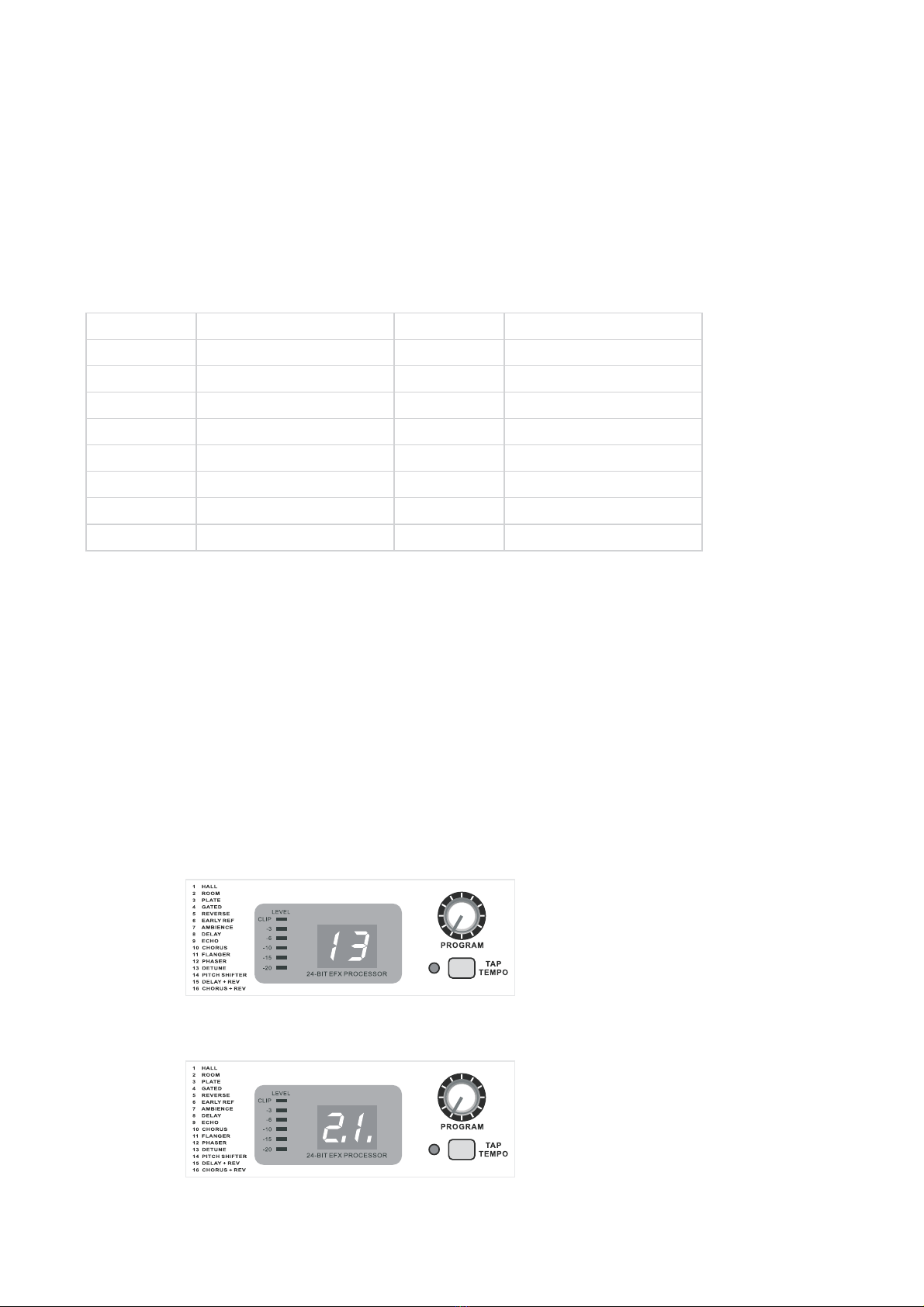
Step 2: Press Tap switch to select & change Time Interval parameter. The display will show number with decimal point on
lower right corner.
41. Level: The LED level meter on the effects module displays the level fed to the effects processor. Take care to ensure that the clip
LED only lights up at peak levels. If it is lit constantly, you are overloading the effects processor and this could cause unpleasant
distortion. The EFX SEND knob determines the level that reaches the effects module. .
42. 24-BIT EFX PROCESSOR: Here you can find a list of all presets stored in the multi-effects processor. This built-in effects module
produces high quality standard effects such as reverb, chorus, flanger, delay and various combination effects.
These effects presets are designed to be added to dry signals. A signal has to be fed into the effects processor via the EFX send
knob in each channel.
The overall EFX send level can be adjusted via EFX SEND knob located below the effects processor module. The level of the effect
processor output can be adjusted via EFX MIX fader, which can be routed to Main and Group outputs.
The effects processor has 16 types of effects in total. Each effects type has two layers of adjustable sub-parameters. These functions
are controlled by the PROGRAM encoder and TAP switch.
43. PROGRAM: This rotary encoder is used to select the effect preset.
Turn the control encoder to select the desired effect preset number. The display flashes as you scroll through the presets
menu.
To confirm the selected preset, press down on the knob. The flashing stops to show that the selected effect type has
been confirm.
PROGRAM
PROGRAM
44. Tap Switch:
•
•
Tap switch is used to select time interval parameter and no. of repetitions.
Please follow the steps to use Tap function.
When the effect type is selected, press down on the encoder to enter the first layer of parameters. The decimal point on the lower
right corner of the display will light up to show that you are in the first layer parameter interface. By turning the encoder at this time,
you can promptly change the selected effect specific parameters. The adjustments made will be immediately reflected in the sound
performance.
Available Effects:
1
2
3
4
5
6
7
Effect No. Effect Name
8
Hall
Room
Plate
Gated
Reverse
Early Ref
Ambience
Delay
Pitch + Shifter
Echo
Chorus
Flanger
Phaser
Detune
Delay + Rev
Chorus + Rev
Effect No.
14
9
10
11
12
13
15
16
Effect Name
Rotate program control to select Effect from list as a printed on panel. The display will show the selected effect no.
from 1 to 16.
Step 1:

Rotate program control to select number of repetitions.Step 3:
5
Note: If the user does not follow the 3rd step, then after 5 seconds the display will return to the main menu & show the selected Effect
from 1 to 16.
Tap function with Time interval parameter (for speed variation) and number of repetitions is available with following effects:
•The Tap function with repetition is available with following effects:
Tap Led: This LED glows when the Tap function is selected. The LED also flashes as per repetition speed.
Effect Name
8
9
10
11
12
13
15
16
Effect No. Tap Switch No. of Repetition
Press Tap Switch to increase or
decrease the repetition Speed
Press Tap Switch to increase
or decrease the repetition
Speed
1 to 20
1 to 40
1 to 99
1 to 94
1 to 94
1 to 99
-9 to + 9
-9 to +9
Delay
Echo
Chorus
Flanger
Phaser
Detune
Delay + Rev
Chorus + Rev
05 or 50
Tap Switch
1
2
3
4
5
6
7
14
Effect No. Effect Name Position Repetition
1 to 10
1 to 10
1 to 10
1 to 10
1 to 10
1 to 10
1 to 10
-12 to +12
On
On
On
On
On
On
On
On
Hall
Room
Plate
Gated
Reverse
Early Ref
Ambience
Pitch + Shifter
6
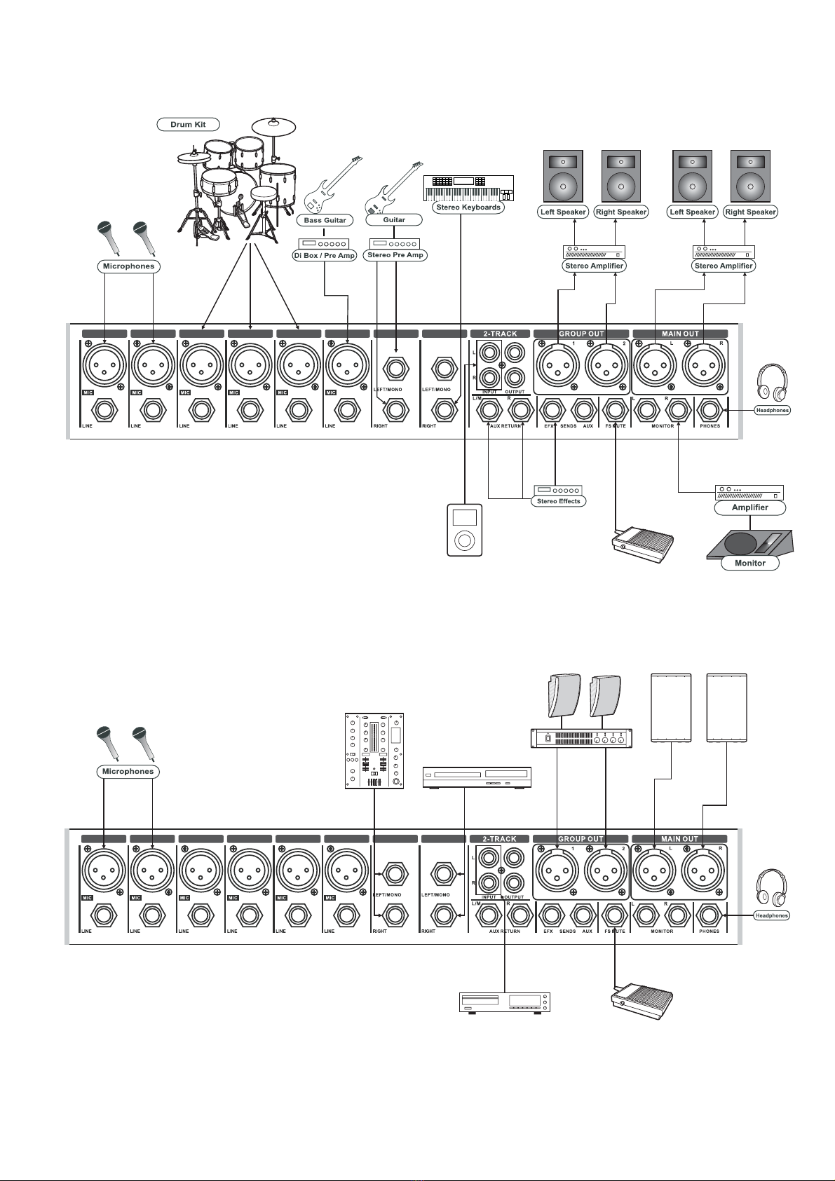
6. Mixer Set Up:
Set up for live P.A. Operation
Set up for Events & Parties
12345678
DJ Mixer
DVD Player (Voice) Poweramp
Speakers
CD Player
Powered Speakers
FS Switch
12345678
Portable audio player
(If External Effect
processor is required)
FS Switch
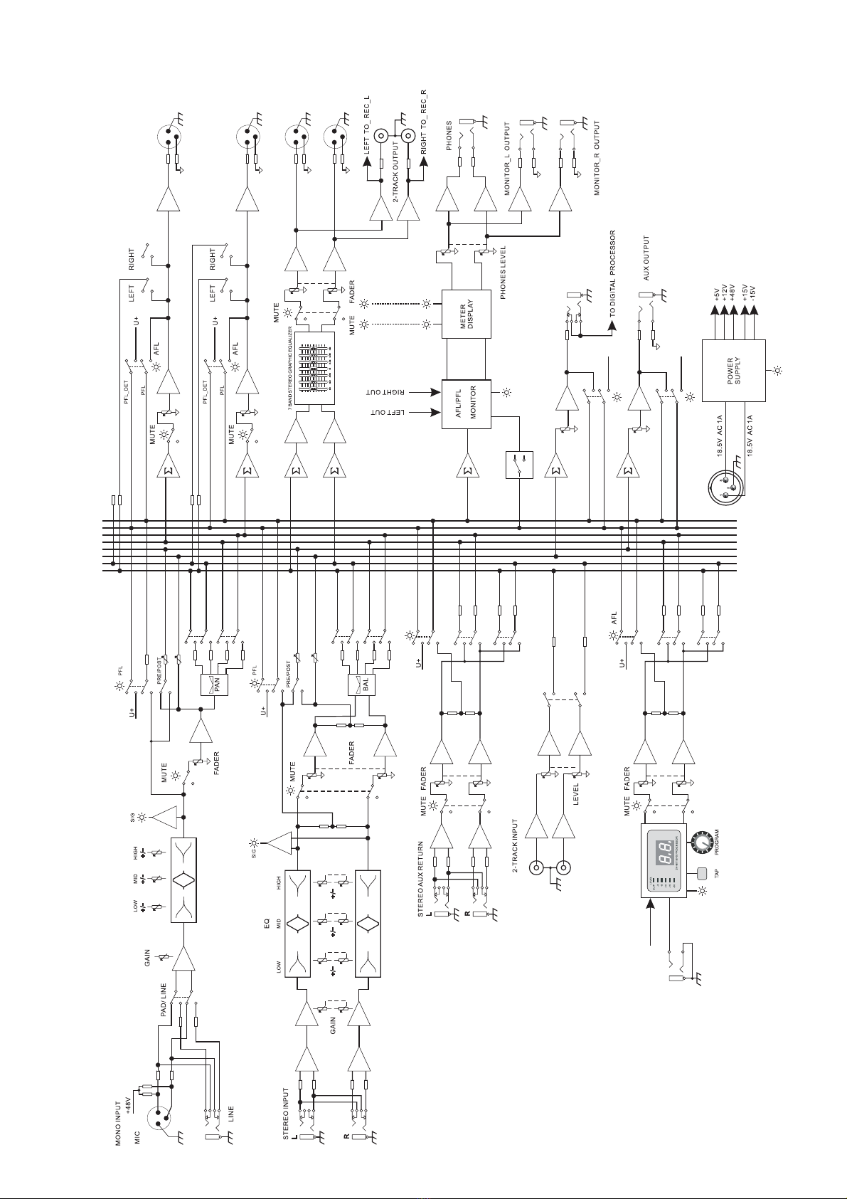
7. Block Diagram:
G1
G2
MAIN_L
MAIN_R
EFX
AUX
PFL\AFL_DET
PFL
G-1 OUT
G-2 OUT
G-1 ASSIGN TO L/R
LEFT OUT
RIGHT OUT
G-2 ASSIGN TO L/R
G-1
MAIN_R
MAIN_L
EFX
AUX
PFL
PFL_DET
G-2
PFL_DET
PFL
AUX
EFX
MAIN_L
MAIN_R
G-1
G-2
G-1
G-2
PFL_DET
PFL
MAIN_L
MAIN_R
MAIN_L
MAIN_R
PFL_DET
PFL
G-1
G-2
MAIN_L
MAIN_R
G1
G2
MAIN_L
MAIN_R
EFX
AUX
PFL\AFL_DET
PFL
G-1
G-2
EFX SEND
EFX OUTPUT
EFX
PFL_DET
PFL
MAIN_L
MAIN_R
AUX
EFX SEND TO DSP PROCESSOR
FS MUTE
24 bit DSP PROCESSOR
L
R
AUX SEND
AFL
AFL/PFL
AFL
U+
U+
AFL
POWER
MAIN AC
INPUT
7

8
8. Technical Specification:
Nominal Gain (Mic/Line/Stereo Line)
Configuration
60dB, 40dB, 20dB
322 x 316.5 x 134
4.5
5.5
430 x 316.5 x 134 538 x 316.5 x 134
5.5 6.5
6.5 7.0
376 x 316.5 x 134
5.0
6.0
80dB, 60dB, 40dB
-10dBu/-60dBu
+10dBu/-40dBu
+10dBu/-20dBu
0dBu
-2dBu
+24dB
+24dB
+20dB
+20dB
+20dB
2KΩ Balanced
20KΩ (Balanced)/10KΩ (Unbalanced)
20KΩ Balanced
10KΩ Balanced
0dBu (0.775V RMS) Nominal/ +22dBu (10V RMS) Max
0dBu (0.775V RMS) Nominal/ +22dBu (10V RMS) Max
-2dB (600mv RMS)/ +22dBu (10V RMS) Max
0dBu (775mv RMS)/ +22dBu (10V RMS) Max
75Ω
75Ω
1KΩ
75Ω
33Ω min
< -122dB
< -85dB
±15dB (12KHz HF / 2.5 KHz MF/60Hz LF)
±15dB (12KHz HF / 2.5 KHz MF/80Hz LF)
16 Effects, 24-Bit EFX Processor
+48V
20Hz to 20KHz (+0/-2dB)
<0.006%
Max Gain (Mic/Line/Stereo Line)
Input Sensitivity
Max Input Levels
Mic (Gain Min/Gain Max)
Line (Gain Min/Gain Max)
Stereo Line (Gain Min/Gain Max)
Aux Return
2-Track In
Mic
Line
Stereo Line
Aux
2-Track
Mic Input
Line Input
Aux Return Input
Tape Record Inputs
Main/Group
Monitor
Record Out
Aux Send
Main/Group
Monitor
Record Out
Aux Send
Phones
ERN Mic Input (150Ω)
Ratio
Output Levels
Output Impedance
Frequency Response
Total Harmonic Distortion
Noise
Equalisation
Mono MIC
Stereo Line
Effect
Phantom supply
Power Supply
Dimensions (W x D x H in mm)
Net Weight (Kgs.)
Input Output Levels
Models Aqua 6
Input Impedance
Gross Weight (Kgs.)
(Treble/Mid/Bass)
(Treble/Mid/Bass)
150V-240V 50Hz, 15W max~
Aqua 8 Aqua 10 Aqua 14
4 Mic/Line +
2 Stereo
6 Mic/Line +
2 Stereo
8 Mic/Line +
2 Stereo
12 Mic/Line +
2 Stereo

9
9. Notes:

Rev001/SM AQUA SERIES/JUNE 2016
* Design and specification are subject to change without notice.
is a registered trademark of Audioplus in India. © Copyright Audioplus, 2008. All rights reserved. Any
unauthorised reproduction or use of logos, images or design elements is strictly prohibited by law. No part of the
compilation may be reproduced in any manner or translated without written permission.
Range of Studiomaster Professional Products.
~ Air Series
~ Diamond Club Series
~ Diamond Supreme Series
~ Platinum Series
~ Diamond Pro-3 Series
~ Pro VI Series
~ DJ Mixers
CD/USB Media Player
~ P - Series
AiR X 10
AiR X 14
AiR X 18
Diamond Club 6.2
Diamond Club 8.2
Diamond Club 8.2 EFX
Diamond Club 12.2
Diamond Club 12.2EFX
Diamond Club 12.2USB
Diamond Club 16.2
Diamond Club 16.2EFX
Diamond Supreme 7
Diamond Supreme 12
Diamond Supreme 12U
Diamond Supreme 16U
C 142
C 142EFX
C 182
Platinum 12 Fx
Platinum Basic MKI
Platinum MKIII
Diamond Pro-3 12.3
Diamond Pro-3 16.3
Pro 16.6
Pro 24.6
EP 7
Auto 4
DJX 325
Playmix 300
DJX 825
DJX 875
DJX 925
DJX 975
MP 4000
MP 2000
PA 1.5
PA 2.0
PA 3.0
PA 4.5
PA 6.0
PA 7.5
~ Club 2000 Series
DPA 2000
DPA 3200
DPA 4500
DPA 5000
DJA 100
DJA 500
DJA 800
DJA 1600
DJA 2500
DJA 3200
DJA 4000
DJA 5000
Arena 20
Arena 30
ARC 120A
ARC 240A
SWF 18120
SWF 18100
SWF 1880
SWF 1560
SMB 1565
SMB 1545
SMB 1530
SMB 1230
SMB 1220
SHF 0104
SHF 0210
EMB 1225
EMB 1530
TWF 1815
TWF 1811
TWF 1580
TMB 1555
TMB 1535
THF 0208
S5225
S8018
S8118
S8128
S8028
Fire 51
Fire 51A
Fire 55
Fire 57
Fire 84
~ DPA Series
~ DJA Series
~ Arena Series
~ Industrial Amplifier
~ S-Series
~ E-Series
~ TITAN Series
~ S-Series
~ Fire Series
SM 100XLR
TRIO 100
TRIO 100
SM 200XLR
SM 300I
SM 400XLR
SM 450XLR
SM 500XLR
SM 600XLR
SM 650XLR
SM 800C
SM 900C
SBM 10
SBM 20
Flex 2/Flex 2B
Flex 4
BR 12 Series
BR 28 Series
BR 48 Series
ER 11 Series
ER 31 Series
ER 58 Series
KR 12 Series
TR 47 Series
Vak 10 System
Vak 10s
Vak 10d / Vak 10c
Vãk 20
SX-2
SX-321
SX-421
SX-521
DD 1000
SEQ 152
SEQ 312
Multi 3
SFX 8
SPS 8
SDX 4
Phantom 11
CUB 4
CUB 6
CUB 6U
AiR 2
AiR 4
AiR 6
AiR 8
AiR 12
AiR 16
AiR Pro 24
~ Cub Series
~ Air Series
XVP 1225
XVP1540
XVP1540M
XVP 1560
XVP 2250
XVP 2550
XVP 2585
XVP 25A2
XVP 25A6
XVP 1808
XVP 1812
XVP 2820
Aria 8
Aria 12
Aria 15
B 200
B 400 (Black & White)
B 400U
B 400UB
O 215
O 415
O 415U
O 515
O 12SUB
O 15SUB
O 18SUB
SLA-40 System
SLA-40 T
SLA-40 Kit
S 9022
S 9022 (FK)
Sat 5 / Sat 10S
SPA 25FX
SPA 80FX
SVC - S1000
SVC - S2000
SVC - S3000
SVC - S5000
SVC - S8000
SVC - S10000
SVC - S12000
SS 10B / SS 20S
WS 10
~ XVP Series
~ ARIA Series
~ B Series
~ OP Series
~ SUB Series
Wired Microphones
Wireless Microphones
Conference System
Processors
Mixers
Amplifiers
Passive Speakers
Stabilizers
Speaker Component
Line Array System
Powered Speaker
Speaker Stand
Crossovers
Active Monitors
Sound Box
A A Giriraj Industrial Estate Mahakali Caves Road Andheri East Mumbai India. Tel
Fax Whats App 8888887049 E info audioplus india com
W www studiomasterprofessional com www audioplus india com
1/ 2, , , ( ), - 400 093 .: +91-22-42869043 /
4286 9076 / : +91-22-26871453 .: +91- @ - .
../.-.
This manual suits for next models
4
Table of contents
Other Studiomaster Professional Music Mixer manuals


