Studiomaster Professional FIRE 92 User manual

Step into the amazing world
of Line Array Systems with the
Studiomaster Professional Advantage
FIRE 92 - LINE ARRAY
92
92
92
92
92
92
92
92

2
TABLE OF CONTENTS
1. ...................................................................................................................................................................................... 3IMPORTANT NOTES
2. ...................................................................................................................................................... 3IMPORTANT SAFETY PRECAUTIONS
3. ............................................................................................................................................................................................ 4INTRODUCTION
4. .......................................................................................................................................................................................................... 4FEATURES
5. .................................................................................................................................................................. 6INTERNAL WIRING DIAGRAM
6. ................................................................................................................................................................. 6REAR PANEL & CONNECTION
7. ....................................................................................................................................................................... 7SYSTEM CONFIGURATION
8. INSTALLATION (FLYING)
8.1 General ....................................................................................................................................................................................................... 8
8.2 Fly Bar assembly ........................................................................................................................................................................................ 9
8.3 Joining the Enclosure to the Fly Bar ………..................................................................................…………….............………................…. 10
8.4 Joining Enclosures ………………………………………………………….......................................................................................................….. 11
8.5 Variable Splay Angle adjustment ........................................................................................................................................................... 12
9. VERTICAL DIRECTIVITY (COVERAGE AREA)
1. All enclosures fitted with 0 deg splay angle – total vertical directivity 9° ............................................................................................. 13
2. All enclosures fitted with 3 deg splay angle – total vertical directivity 30° .......................................................................................... 13
3. All enclosures fitted with 6 deg splay angle – total vertical directivity 51° .......................................................................................... 14
4. All enclosures fitted with 9 deg splay angle – total vertical directivity 72° .......................................................................................... 14
10. .................................................................................................................................................................................. 15NOTES ON FLYING
11. ............................................................................................................................................................... 15TECHNICAL SPECIFICATIONS
3
1. IMPORTANT NOTES
•Before connecting and using this product, please read this instruction manual carefully.
•Be sure to follow all the precautionary instructions in this section, which contain important warnings and/or cautions regarding safety.
•The manual is to be considered as integral part of this product and must accompany it when it changes ownership as a reference for
correct installation and use as well as for the safety precautions.
•Install in accordance with Studiomaster Professional's instructions and under the supervision of a licensed
Professional Engineer only.
•Studiomaster Professional shall not assume any responsibility for the incorrect installation/or use of this product.
Safety symbols and messages described below are used in this manual to prevent bodily injury and property damage which could result
from mishandling. Before operating your product, read this manual first and understand the safety symbols and messages so you are
thoroughly aware of the potential safety hazards.
SAFETY SYMBOL AND MESSAGE CONVENTIONS
1. Loudspeaker lines (amplifier outputs) can have sufficient high voltage to involve a risk of electrocution: never install or connect
speakers when the line is alive.
2. Make sure all connections have been made correctly & speaker impedances are suitable for amplifier.
3. Protect speaker lines from damage; make sure they are positioned in a such way that they can not be stepped on or crushed by any
object.
4. Make sure that no object or liquids can get in to the product as this may cause short circuit.
5. Never attempt to carry out any operations, modifications or repairs that are not expressly mentioned in this manual. Contact your
authorized dealer or qualified personnel if any of the following occur:
The system does not function or works in anomalous way.•
The cable has been damaged.•
Objects or liquid have got in to unit.•
The system has been damaged due to heavy impact or fire.•
6. Before placing, installing, rigging, or suspending any speaker product, inspect all hardware, suspension, cabinets, transducers,
brackets and associated equipment for damage.
7. Any missing, corroded, deformed, or non-load rated component could significantly reduce the strength of the installation, placement
or array. Any such condition severely reduces the safety of the installation and should be immediately corrected.
8. Use only recommended hardware, brackets, joining plates, locking pins etc which are supplied with the unit for
the installation. Never exceed the rating of the hardware or equipment.
Avoid installing or mounting the unit in unstable locations, such as on a rickety table or a slanted surface. Doing so may result in the9.
unit falling down and causing personal injury and/or property damage.
10. Refer all installation work to the dealer from whom the speaker was purchased. Installation for flying requires extensive technical
knowledge and experience. The speaker may fall off if incorrectly installed, resulting in possible personal injury.
2. IMPORTANT SAFETY PRECAUTIONS
Indicates a potentially hazardous situation which, if mishandled,
could result in moderate or minor personal injury, and/or property damage.
Indicates a potentially hazardous situation which, if mishandled,
could result in serious personal injury.

4
11. For Flying be sure to follow the instructions below. Otherwise, the suspension wires or belts may be off or snap & the speaker may
fall off, causing personal injury.
Check to confirm that the suspension wires and belts are strong enough to withstand the speaker load.•
The connectors of the suspension wires and belts must be securely linked with those of the speaker.•
12. Install the unit only in a location that can structurally support the weight of the unit and the mounting bracket. Doing otherwise may
result in the unit falling down and causing personal injury and/or property damage.
13. Owing to the unit's size and weight, be sure that two or more persons are available to install the unit. Failure to do so could result in
personal injury.
14. Do not use other methods than specified to mount the bracket. Extreme force is applied to the unit and the unit could fall off, possibly
resulting in personal injuries.
15. Tighten each nut and bolt securely. Ensure that the bracket has no loose joints after installation to prevent accidents that could result
in personal injury.
16. Do not mount the unit in locations exposed to constant vibration. The mounting bracket can be damaged by excessive vibration,
potentially causing the unit to fall, which could result in personal injury.
1. Do not operate the unit for an extended period of time with the sound distorting. This is an indication of a malfunction, which in turn
can cause heat to generate and result in a fire.
2. Do not stand or sit on, nor hang down from the unit as this may cause it to fall down or drop, resulting in personal injury and/or
property damage.
3. Should the unit emit any strange odours or smoke, remove it from line after having the amplifier switched off.
4. Exposure to high sound levels can cause permanent hearing loss. The acoustic pressure level that leads to hearing loss is different
from person to person and depends on the duration of exposure. To prevent it wear ear plugs or protective earphones.
3. INTRODUCTION
4. FEATURES
•High performance dual 12”LF & two High quality 2”HF transducers.
•Exceptional sound quality, powerful response & long throw.
•High grade & durable cabinet design.
•Easy carry handles & heavy duty protective grille.
•Fast, integral rigging system with variable splay angles.
•HF frequency attenuation for selection of throw.
Constant Curvature waveguide for unprecedented array coherence.•
Coverage Pattern: 120 degree x 9 degree nominal (horizontal x vertical), single unit.•
Extra textured anti-scratch paint finish.•
High-quality passive crossover network for maximum reliability.•
Studiomaster Professionals line-array systems set new standards in handling, flexibility and profitability by using most modern
technology and materials. The Fire 92 series is simple to use & understand, quick to rig up !
The Fire 92 is a specially designed loudspeaker module designed to form a vertical stack in varying numbers. This stack is usually
flown to provide superior sound coverage in the intended listening areas. Stacked Fire 92 modules form a line array for constructive
summing & increased coupling. Sound disperson of Fire 92 array has a very narrow vertical dispersion angle. Therefore sound can
be precisely directed where audience is present.

5
Fire 92 System Consists of:
•Fire 92: High performance dual 12’’ LF + 2”HF, 2 way passive, 1100 watts line array module.
•Fire 92 Kit: Fly bar & rigging hardware. (To be ordered separately).
Enclosure Features:
The Fire 92 incorporates 2 x 12’’ Mid-Bass transducers & 2 x 2’’ High Quality HF transducers with state of the art Waveguide horn, all
comprised into a sleek enclosure. This Array module has a horizontal coverage angle of 120 & vertical Coverage angle of 9 .° °
About Waveguides:
Sound Waves in open space propagate in all directions, this way they lose their power
significantly. In order to counter this problem the Fire 92 incorporates waveguide driver
to ensure maximum control on power & dispersion. This ensures pure performance and
negates the possibilities of phase cancellations.
Enclosure hardware:
LOCKING PIN BIG 25MM (SILSSSKR001)JOINING PLATE ( )SMLSSSKS003
Fire 92 Kit: The Fire 92 Kit is set of essential hardware required for rigging flying this line array system. It consist of ultra durable
Flybars / Array Frames & Quick Release Pins (Push-Pull Bullets). This kit makes flying the Fire 92 Series easy.
INNER JOINING
PLATE SMALL
(SMLSSSKS005)
INNER JOINING
PLATE BIG
(SMLSSSKS004)
LOCKING PIN
SMALL 20MM
(SSLSSSKP006)
SUSPENSION
BRACKET
(SMLSSSKS006)
FIRE 92
FLY BAR
(SSLSSSKP010)
Qty.:- 2 Nos.
Qty.:- 4 Nos. (Speaker Cabinet Packing)
Qty.:- 1 No. Qty.:- 4 Nos. Qty.:- 2 Nos. Qty.:- 2 Nos. Qty.:- 8 Nos.
0°
3°
6°
9°
92
Note: Flybar & rigging hardware is not part of enclosure hence it need to be ordered separately as per requirement.
LOCKING PIN
BIG 25MM
(SILSSSKR001)
Qty.:- 8 Nos.
6
5. INTERNAL WIRING DIAGRAM
INPUT
HF HI/LO SWITCH
LF 12’’
LF 12’’
HF 2’’
HF 2’’
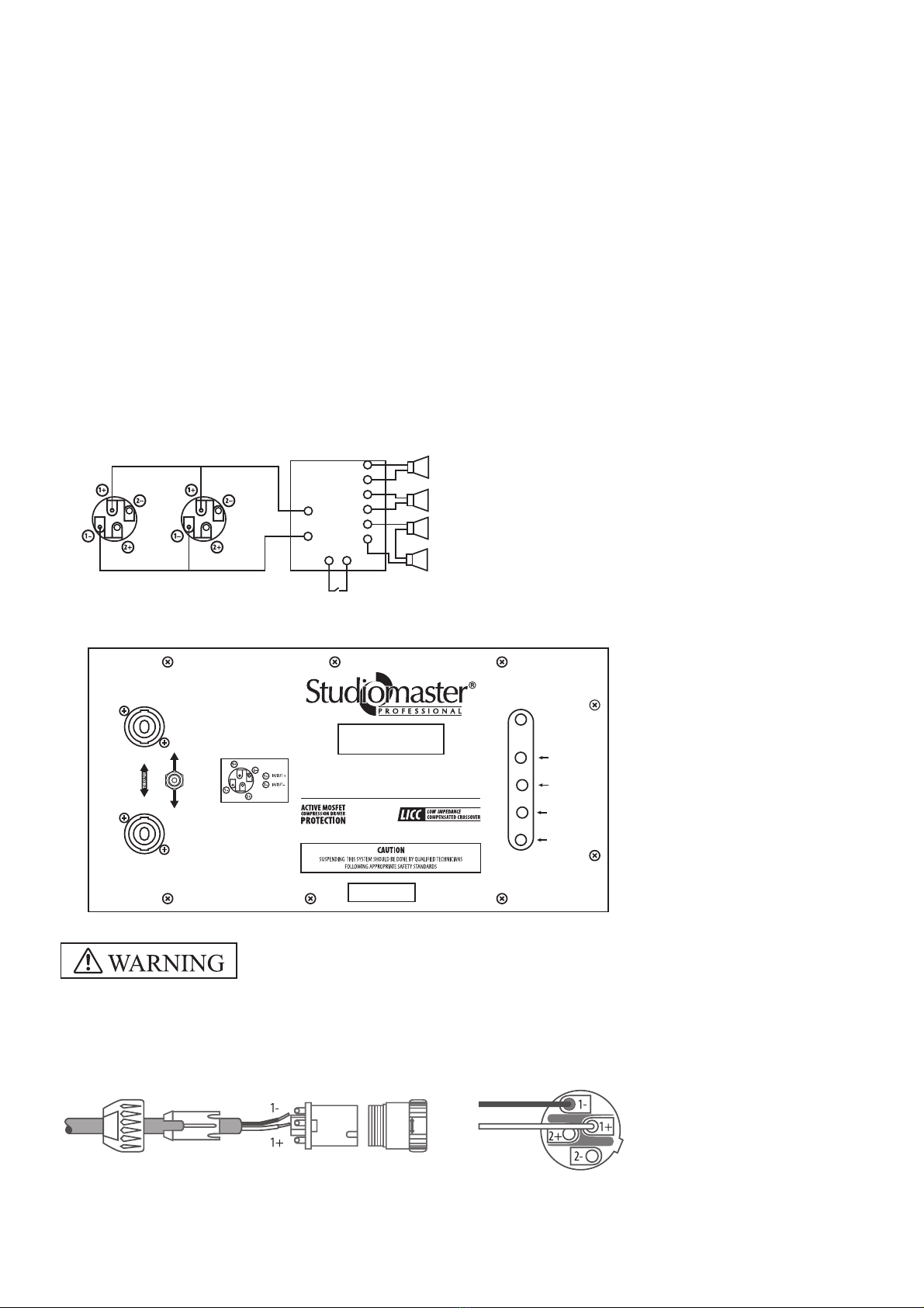
6. REAR PANEL & CONNECTION
Advantages of a using the Fire 92 line array:
Studiomaster Professional Fire 92 has several advantages over the horizontally stacked speaker systems normally used for covering large
events. These are:
•Higher direct to reverberant ratio due to directional nature of the system and therefore better intelligibility.
•Increased feedback rejection due to increased directionality in vertical plane and therefore more acoustic gain available.
•Frequency response is uniform over the coverage area.
•Because of increased HF throw of the system, need for delay stacks is eliminated or reduced.
•Even sound pressure level can be achieved over the entire listening area by proper articulation of the vertical array formed by Fire 92.
•More stage space available as Fire 92 arrays are flown.
The Fire 92 system can be configured in any of the following vertical formations:
•Straight Array - all modules are without tilt.
•Curved Array - upper modules are curved up towards ceiling and lower ones are curved down.
•J Array - upper modules are without any tilt and lower ones are curved down.
•Spiral Array - The topmost module/ modules is/ are without tilt and the subsequent modules have increasing tilt with the lowest having
maximum tilt with varying splay angles 3 6 9 .
°, °, °
WARNING: To prevent risk of electric shock, do not connect the speaker with the amplifier
switched on. Before using the speaker, make sure that all connections are made correctly
to prevent accidental short circuit from giving rise to electric sparks.
Speakon Connectors: There are two Speakon connectors. One socket is used for audio signal input from amplifier output and other
socket can be used as output for parallel connection of another speaker.
HF Switch: HF switch is used to long throw or short throw on the application. In HI position HF is increased by about 2dB compared LO
position.
Pin1+ =Signal (+)
Pin1 =Ground (-)-COLD
HOT
FIRE 92
R
IMPEDANCE 8Ω
RMS POWER : 1100W
PEAK POWER : 2200W
Ω
MADE IN P.R.C.
SERIAL No.
LINE ARRAY
Designed & Engineered in INDIA
HI
HF
NORMAL
0°
3°
6°
9°

92
92
92
92
92
92
92
92
92
92
92
92
92
92
92
92
7
You can configure Line array system with amplifiers as shown below.
7. SYSTEM CONFIGURATION
Configuration 1:- Individual speaker loading (8 Impedance).Ω
Configuration 2:- Two speakers in parallel (4 Impedance).Ω
Configuration 1
PA 3.0 / DPA 3200
8Ω
CH 2
8Ω
AMP 1
AMP 2
AMP 3
AMP 4
FIRE 92
CH 1
Configuration 2
PA 4.5 / DPA 4500
4Ω
CH 2
4Ω
Link
Link
Link
Link
FIRE 92
CH 1 AMP 1
AMP 2

8
8. INSTALLATION (FLYING)
8.1 General
Use Fly bar for flying the Line Array speakers. With the use of the Fly bar, up to 8 Line Array speakers can be arranged in flying
configuration. When joining two or more speakers, or joining the Fly bar and the speaker, use the Joining Plates supplied with the
system.
The vertical directivity angle of the Line Array speaker is 9 degrees. The horizontal directivity angle is fixed at 120 degrees.
To transmit sound over long distances, you can adjust splay angles as 0, 3, 6 & 9 degrees. The splay angle can be adjusted by means
of the Inter Joining Plates used to join the speakers. It is very easy to do by just quick release locking pins.
Fig. 1
30°
Fig. 3
Inner Joining
Plate Small
(SMLSSSKS005)
30°
Fig. 2
Speaker Inter
Joining Plate
(SMLSSSKS003)
Inner Joining
Plate Big
(SMLSSSKS004)
9°
Inner Joining
Plate Small
(SMLSSSKS005)
Long Throw
AB
Medium &
Short Throw
4.5°
Fly Bar

9
For assembling, refer to the figure & procedure below.
Tighten 4 supplied M12X60 bolts with plain washers, spring washers and nut securely to fix each Suspension Bracket to the Fly bar.•
Fix Inner Joining Plate Small (SMLSSSKS005) on front side & Inner Joining Plate Big (SMLSSSKS004) on back side to Suspension brackets•
by 20mm Locking pin (SSLSSSKP006). Inner joining plate small can also used on rear. It gives 4.5° vertical inclination (downward).
FINISHED ASSEMBLY DIAGRAM OF FLY BAR
8.2 Fly bar Assembly
Use only shackle holes for suspension of array!
A :- M12x60 HEX BOLT SMLSSSKS010 (4 NOS.)
B :- SUSPENSION BRACKET SMLSSSKS006 (4 NOS.)
C :- LOCKING PIN SMALL (20MM) SSLSSSKP006 (4 NOS.)
D :- INNER JOINING PLATE BIG SMLSSSKS004 (2 NOS.)
E :- INNER JOINING PLATE SMALL SMLSSSKS005 (2 NOS.)
F :- FLY BAR SSLSSSKP010 (1 NO.)
G :- M12x10 HEX NUT SMLSSSKS007 (4 NOS.)
H :- M12 SPRING WASHER SMLSSSKS008 (4 NOS.)
I :- M12 PLAIN WASHER SMLSSSKS009 (8 NOS.)
A
B
C
D
E
F
G
H
I
10
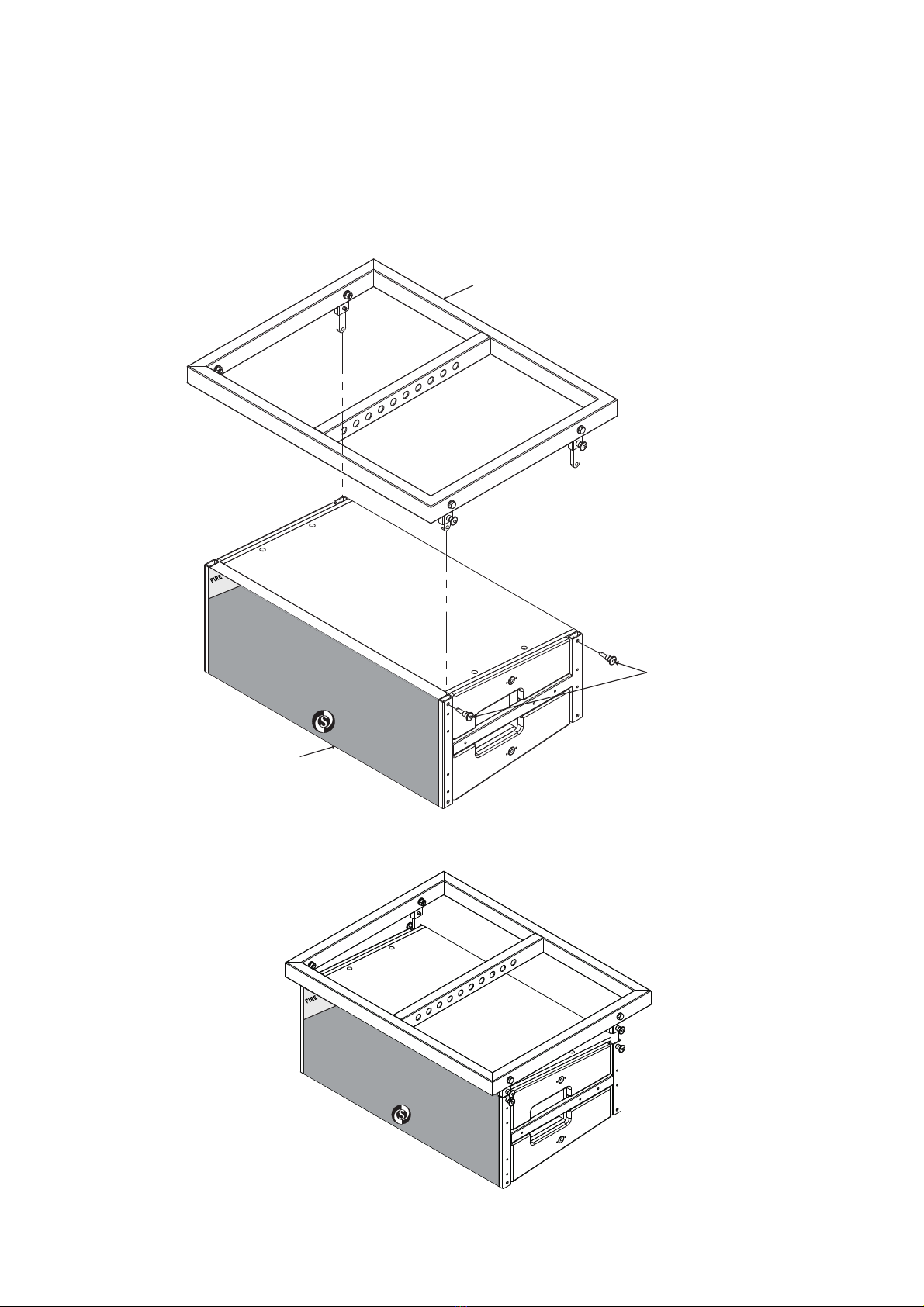
8.3 Joining the Enclosure to the Fly bar
Follow the procedure below to mount the enclosure to the Fly bar, as shown in the assembly diagrams below.
Use Fly bar assembly as mentioned in 8.2.•
Place speaker box in line with Fly bar.•
Please ensure that speaker direction is correct (“Studiomaster Professional”Logo on bottom side).•
Insert Inner Joining Plates to side channel of speaker box as shown in figure below.•
Fix quick release 20mm Locking Pin (SSLSSSKP006).•
FINISHED SPEAKER CABINET ASSEMBLY DIAGRAM
FLY BAR ASSEMBLY
LOCKING PIN SMALL (20MM)
SSLSSSKP006 (4 NOS.)
SPEAKER CABINET
92
92

11
8.4 Joining Enclosures
Follow the procedure below to mount the enclosure to the Fly bar as shown in the assembly diagrams below.
Use Fly bar assembly as mentioned in 8.2•
First fix Joining Plate (SMLSSSKS003) to upper speaker box using quick release 25mm Locking Pin (SILSSSKR001) on front & back side.•
Fix M10X30 Hex bolt to upper speaker as shown in assembly below. This gives additional strength & safety to Line array assembly.•
Align speaker as shown in drawing below.•
Please ensure that lower speaker direction is correct (“Studiomaster Professional”Logo on bottom side).•
Now fix quick release 25mm Locking Pin (SILSSSKR001) to lower speaker box & Joining Plate. You can adjust Splay Angles 0 , 3 , 6 & 9•
as shown below assembly
FINISHED JOINING ENCLOSURES ASSEMBLY DIAGRAM
C:- M10x30 HEX BOL (4 NOS.)T SMLSSSK002
D:- INTER JOINING PLATE SMLSSSKS003 (2 NOS.)
B:- ADJUSTABLE HOLES FOR SPLAY ANGLES
A:- LOCKING PIN BIG (25MM) SILSSSKR001 (8 NOS.)
E:- ADJUSTABLE SLOT FOR SPLAY ANGLES
F:- SPEAKER CABINET ASSEMBLY
A
B
A
C
D
E
F
92
92
92
92
12
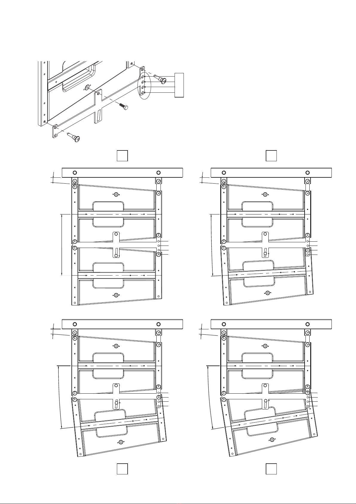
8.5 Variable Splay Angle adjustment
Splay angle can be adjusted using Joining plate holes as shown below.
0° 3°
6° 9°
3°
0°
3°
6°
9°
4.5°
9°
6°
3°
0°
6°
0°
3°
6°
9°
4.5°
9°9°
0°
3°
6°
9°
4.5°
0°
0°
3°
6°
9°
4.5°

2. All enclosures fitted with 3 deg splay angle – total vertical directivity 30°.
13
9. VERTICAL DIRECTIVITY (COVERAGE AREA)
With different Splay angles we can cover required area. The overlapping angle can be adjusted by
means of the combination of different splay angles using holes on Joining Plate as explained in point 8.5. The horizontal directivity
angle is fixed at 120 degrees. Please see below different coverage areas.
In below configuration of each splay angle,
1. First speaker is at 4.5° inclination w.r.t. fly bar which is to be used for long throw. On front, small joiningConfiguration A -
plate are used & on rear big joining plate are used.
2. - Front speaker is parallel to fly bar. This configuration can be used for medium & short throw. On bothConfiguration B
ends, small joining plate are used.
9°
1. All enclosures fitted with 0 deg splay angle – total vertical directivity 9°.
Long Throw
A
A
B
B
Long Throw
Medium &
Short Throw
Medium &
Short Throw
9°
4.5°
30°
4.5°
30°

14
3. All enclosures fitted with 6 deg splay angle – total vertical directivity 51°.
4. All enclosures fitted with 9 deg splay angle – total vertical directivity 72°.
72°
Long Throw
Long Throw
Medium &
Short Throw
Medium &
Short Throw
51°
4.5°
51°
72°
4.5°
A
A
B
B

15
10. NOTES ON FLYING
•Check to confirm that the suspension wires, belts, construction of the ceiling, etc are strong enough to withstand the speaker
load.
Tighten each joint bolt to 300-350 kg-cm of torque securely. Be sure to use the joint bolts supplied with the speaker and the•
Fly bar.
Up to 8 Line Array speakers can be arranged in flying configuration per one Fly bar. No more than 8 speakers can be•
arranged in flying configuration.
Use a suspension point that provides the desired downward angle. The downward angle increases as the suspension point is•
moved backward.
•Use safety belts for further safety.
11. Technical Specifications:
Recommended products to be used with Fire 92.
1) Subwoofer : Fire 82 (1 x 18’’ woofer, 1500Wrms / 3000W peak power)
Fire 84 (2 x 18’’ woofer, 2000Wrms / 4000W peak power)
S 8128 (2 x 18’’ woofer, 2000Wrms / 4000W peak power)
S 8028 (2 x 18’’ woofer, 3000Wrms / 6000W peak power)
2) Speaker Management System - SDX 4
System Type
Frequency Range (-10 dB)
RMS Power
Peak Power
System Maximum SPL
Sensitivity (1w @ 1m) dB
Crossover Frequency
Nominal Impedance
Connectors
Horizontal Coverage Angle
Vertical Coverage Angle
Variable splay angles
LF Component
HF Component
Enclosure
Dimensions (L x W x H) mm
Net Weight (Kg)
Electrical Parameters
2-Way
80-18 KHz
1100W, 2 X ( LF=500 W + HF=50W )
2200W, 2 x ( LF=1000 W + HF=100W )
133 dB
98dB LF / 100dB HF
2200 Hz
8 Ohm
2 X Speak-on
120°
9°
0, 3, 6 & 9 deg C
2 x 12" Woofer
2 x 2" Driver
15 mm Plywood
960 x 560 x 386
60Kg
Connectors
Coverage Angles
Components
Mechanical

REV. 03/SM FIRE 92 LINE ARRAY\JANUARY 2017
* Design and specification are subject to change without notice.
is a registered trademark of Audioplus in India. © Copyright Audioplus, 2008. All rights reserved. Any
unauthorised reproduction or use of logos, images or design elements is strictly prohibited by law. No part of the
compilation may be reproduced in any manner or translated without written permission.
A A Giriraj Industrial Estate Mahakali Caves Road Andheri East Mumbai India1/ 2, , , ( ), - 400 093.
Tel 9000 001 Fax WhatsApp : +91-8888887049.: +91-22-4286 / : +91-22-26871453
E info audioplus india com W www studiomasterprofessional com www audioplus india com@ - . . . / . - .
Range of Studiomaster Professional Products.
~ Air Series
AiR X 10
AiR X 14
AiR X 18
~ AQUA Series
Aqua 6
Aqua 8
Aqua 10
Aqua 14
~ Digital Mixer
D. Mix 20
~ Diamond Club Series
Diamond Club 6.2
Diamond Club 8.2
Diamond Club 8.2 EFX
Diamond Club 12.2
Diamond Club 12.2EFX
Diamond Club 12.2USB
Diamond Club 16.2
Diamond Club 16.2EFX
~ Diamond Supreme Series
Diamond Supreme 7
Diamond Supreme 12
Diamond Supreme 12U
Diamond Supreme 16U
~ Club 2000 Series
C 142
C 142EFX
C 182
~ Platinum Series
Platinum 12 Fx
Platinum 16
Platinum 16 Fx
~ Diamond Pro-3 Series
Diamond Pro-3 12.3
Diamond Pro-3 16.3
~ DJ Mixers
DJX 300
DJX 325
Playmix 300
DJX 825
DJX 825
DJX 875
DJX 925
DJX 975
CD/USB Media Player
MP 2000
~ P - Series
PA 1.5
PA 2.0
PA 3.0
PA 4.5
PA 6.0
PA 7.5
~ DPA Series
DPA 2000
DPA 3200
DPA 4500
DPA 5000
~ DJA Series
DJA 100
DJA 500
DJA 800
DJA 1600
DJA 2500
DJA 3200
DJA 4000
DJA 5000
XJA 2600
~ Arena Series
Arena 20
Arena 30
~ Industrial Amplifier
ARC 120A
ARC 240A
ARC 480A
~ S-Series
SWF 18120
SWF 18100
SWF 1880
SWF 1560
SMB 1565
SMB 1545
SMB 1530
SMB 1250
SMB 1230
SMB 1220
SHF 0104
SHF 0210
~ E-Series
EMB 1225
EMB 1530
~ TITAN Series
TWF 2115
TWF 1815
TWF 1811
TWF 1580
TMB 1555
TMB 1535
THF 0208
~ S-Series
S5225
S8018
S8118
S8128
S8028
~ Fire Series
Fire 21 / Fire 51
Fire 51A
Fire 55 /
Fire 57
Fire 82
Fire 84
SM 100XLR
TRIO 100
SM 200XLR
TRIO 200
SM 300I
SM 400XLR
SM 450XLR
SM 500XLR
SM 600XLR
SM 650XLR
SM 800C
SM 900C
SBM 10
SBM 20
Flex 2/Flex 2B
Flex 4
BR 28 Series
BR 48 Series
ER 7 Series
ER 11 Series
ER 31 Series
ER 58 Series
KR 12 Series
TR 47 Series
XR 40 Series
XR 100 Series
Vak 10 System
Vak 10s
Vak 10d / Vak 10c
Vak 20
SX-2
SX-321
SX-521
SEQ 152
SEQ 302F
SEQ 312
Multi 3
SFX 8
SPS 8
SDX 4
Phantom 11
~ Cub Series
CUB 4
CUB 6
CUB 6U
~ Air Series
AiR 2
AiR 4
AiR 6
AiR 8
AiR 12
AiR 16
AiR Pro 24
AiR Pro 28
AiR Pro 36
~ XVP Series
XVP 1225
XVP 1540
XVP 1540M
XVP 1560
XVP 2250
XVP 2550
XVP 2585
XVP 25A2
XVP 25A6
XVP 1808
XVP 1812
XVP 2820
EKS 151
Q 400
~ ARIA Series
Aria 8
Aria 12
Aria 15
~ A Series
A 200
A 400
A 500
A 600
H 400
~ B Series
B 200
B 400 (Black & White)
B 400U
B 400UB
~ OP Series
O 415
O 515
~ SUB Series
O 12SUB
O 15SUB
FIRE 92
SLA-40 T
SLA-40 Kit
SLA 30
S 9022
S 9022 (FK)
SVC - S1000
SVC - S2000
SVC - S3000
SVC - S5000
SVC - S8000
SVC - S10000
SVC - S12000
SS 20S
WS 10
Wired Microphones
Wireless Microphones
Conference System
Processors
Mixers
Amplifiers
Passive Speakers
Stabilizers
Speaker Component
Line Array System
Powered Speaker
Speaker Stand
Crossovers
This manual suits for next models
1
Table of contents
Other Studiomaster Professional Speakers System manuals


