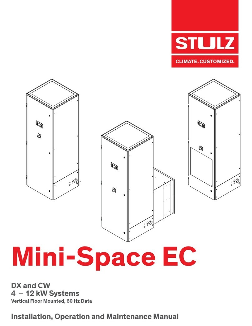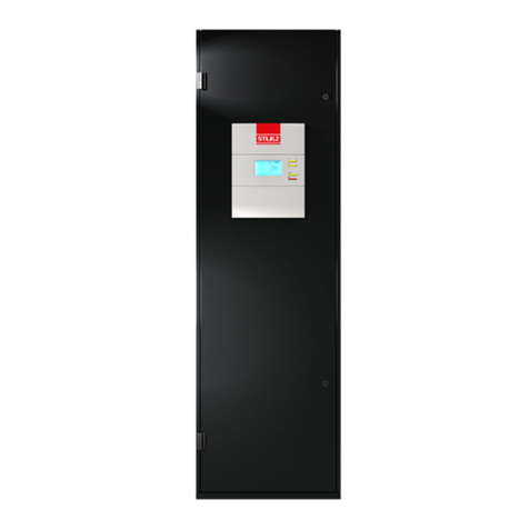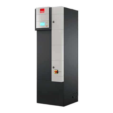
CyberOne EC DX IOM Manual
2.9.1 Low/High Pressure Limit Switch ............................ 26
2.9.2 Head Pressure Controls-AirCooled Systems..... 27
2.9.2.1 Condenser Fan Cycling (Condenser Model SCS-
AA, 0 °F ).......................................................................... 27
2.9.2.2 Condenser Multi-Speed Fan Switch (Model HES-
CAA , 0 °F )...................................................................... 27
2.9.2.3 Variable Condenser Fan Speed (Condenser Model
SCS-SA, -20 °F)........................................................... 27
2.9.2.4 Intelligent Control (Condenser Model SCS-EC
only, -20 °F) ................................................................... 27
2.9.2.5 Flooded Head Pressure Control (Condenser
Model SCS-AA with Fan Cycling, -30 °F)............. 27
2.9.2.6 Flooded Head Pressure Control (Condenser
Model HES-CAA , -30 °F) ......................................... 28
2.9.3 Head Pressure Controls-Water/Glycol Cooled
Systems........................................................................... 28
2.9.4 Humidifier Adjustment................................................ 28
2.9.5 EC Fan ............................................................................. 28
2.9.6 Thermal Expansion Valve........................................... 28
2.9.7 Hot Gas Reheat (Optional) ........................................ 28
2.9.8 Hot Gas Bypass (Optional) ........................................ 29
2.9.8.1 Snap Acting.................................................................... 29
2.9.8.2 Full Floating.................................................................... 29
3.0 Commissioning, Operation and
Decommissioning ........................................ 30
3.1 Commissioning.............................................................. 30
3.1.1 Start-Up .......................................................................... 30
3.1.2 Microprocessor Controller Programming........... 30
3.2 Decommissioning the Unit ........................................ 30
3.2.1 Recovering Refrigerant.............................................. 31
3.2.2 Labeling the Decommissioned Unit ....................... 31
4.0 Maintenance ................................................ 32
4.1 Periodic General Maintenance................................. 32
4.1.1 CyberOne EC DX A/C Unit........................................ 32
4.1.1.1 Air Filter ........................................................................... 32
4.1.1.2 EC Fan ............................................................................. 32
4.1.1.3 Drain Pan......................................................................... 32
4.1.1.4 Coils .................................................................................. 32
4.1.1.5 Heat/Reheat ................................................................. 32
4.1.1.6 Humidifier ....................................................................... 32
4.1.1.7 Condensate Pump ....................................................... 33
4.1.2 Condenser...................................................................... 33
4.2 Troubleshooting ........................................................... 33
4.3 Field Service .................................................................. 38
4.3.1 Leak Detection.............................................................. 38
4.3.2 Leak Repair.................................................................... 38
4.3.3 Refrigerant Piping........................................................ 38
4.3.4 General Common Repairs/Component
Replacement ................................................................. 38
4.3.4.1 Compressor Failure ..................................................... 38
4.3.4.2 Standard Cleanout Procedure ................................. 39
4.3.4.3 Burn-Out/Acidic Cleanup Procedure.................... 39
4.3.4.4 Humidifier Cylinder Replacement........................... 39
5.0 Product Support...........................................41
5.1 Technical Support ........................................................ 41
5.2 Obtaining Warranty Parts .......................................... 41
5.3 Obtaining Spare/Replacement Parts.................... 41
Installation Checklist ............................................42
Glossary ................................................................. 45
Figures
Figure 1. Typical Internal Layout- Downflow
Configuration............................................................. 4
Figure 2. Typical Internal Layout- Upflow
Configuration............................................................. 4
Figure 3. Free Cooling Diagram............................................. 6
Figure 4. Alternate WaterSource Diagram........................ 7
Figure 5. Recommended Installation Clearance.............. 8
Figure 6. Typical Installation.................................................... 9
Figure 7. Downflow Configuration Typical Air
Patterns.................................................................... 10
Figure 8. Upflow Configuration TypicalAir Patterns .... 11
Figure 9. Optional Floor Stand Installation...................... 12
Figure 10. Condensate Pump................................................ 16
Figure 11. Sample Nameplate............................................... 16
Figure 12. Transformer Schematic ....................................... 18
Figure 13. Interconnecting Field Wiring Remote
Condenser............................................................... 19
Figure 14. Interconnecting Field Wiring Remote
Condensing Unit.................................................... 20
Figure 15. Interconnecting Field Wiring Glycol
Systems.................................................................... 21
Tables
Table 1. Weight of Refrigerant (lb/100 ft of
type L tubing).......................................................... 23
Table 2. Weight of Refrigerant For A/C Units (lb)........ 23
