CONDENSER IOM MANUAL
5
1.4.2 Fan Assembly
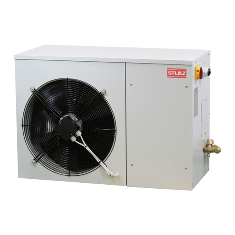
The condenser is equipped with high efficiency axial type,
impeller fan(s) rated for outdoor applications. The quantity of
fans vary depending upon the capacity of the unit. The fan(s)
use corrosion resistant, multi-blade impellers designed for
high aerodynamic efficiency which results in lower power
consumption, lower noise levels and longer life. Each fan uses a
direct driven motor with maintenance free bearings. The fan
motors are internally protected fromoverload.
1.4.3 Electric Box
Theelectrical componentsareprotected in a weatherresistant
enclosurelocated attheheader end oftheunit.Theelectric box
has a removable front access panel which is safety interlocked
with the service disconnect switch, preventing the panel from
being removed when the switch is in the “On” position. The
switch must be turned “Off” to gain access to the electrical
components.
1.4.4 Receiver (Optional)
Receivers are furnished for air cooled condensers using
flooded head pressure control for low ambient temperature
conditions. The optional receivers are equipped with pressure
relief valves and heaterpads.
Receivers for SCS condensers are mounted to a coated steel
base frame which may be attached to a suitable foundation
next to the condenser (see Figure 7). A head pressure control
valve may be shipped loose for field installation to the receiver
if one is not already provided in the indoorA/C unit.
TheSTULZ SCS-MC condenserdesigndiffersinthatreceivers
are integrally mounted to the condenser Frame (See Figure 2).
For-30 °F applicationsa head pressure controlvalveisfactory
installed and piped to thereceiver.
1.5 Head Pressure Controls
1.5.1 Condenser Fan Cycling (AA Models)
Used for outdoor installations where ambient condenser air
inlet temperatures are 0 °F or higher, a condenser fan cycling
switch monitors refrigerant discharge pressure and turns on
the condenserfan as requiredto maintain allowable condenser
pressures. This is a high-pressure differential control switch
with SPST contacts and an automatic reset. The switch
activates the condenserfan contactor to maintain condensing
temperature when the discharge pressure rises. See Table 1
on page 6 for the fan cycling pressure control settings.
NOTE: It may be necessary to alter the fan cycling control
settings on a case by case basis. This is due, in part, to site
specific heat loads and varying BTU capacities of indoor
evaporator (A/C) units. Contact STULZ Product Support for
assistance.
On single circuit condensers, each fan is controlled with its
own fan cycling switch. Multiple fans are staged to operate
sequentially as discharge pressure rises. The primary fan
(closest to the header) turns on 1st as described above. If
pressure continues to rise, adjacent fan(s) are set to turn on
in sequential increments with the fan located furthest from
the headerturning on last. Conversely, as discharge pressure
drops, the fans drop out sequentially in reverse order. .
Dual Circuit condensers employ a fan cycling pressure
control switch for each refrigeration circuit. For smaller model
condensers, two control switches (one per refrigeration
circuit) are adjusted to the same pressure setpoint and are
wired in parallelto operate a single fan. If either control switch
senses a rise in pressure, the fan will turn on. On dual circuit
units with multiple fans, operation of each additional fan
requires two paralleled pressure control switches (one for
each refrigeration circuit). Each set of paralleled switches
will be set to the same pressure such that the adjacent fans
begin operating at sequentially higher pressureincrements.
For larger model micro-channel condensers (SCS-MC-111
through SCS-MC-334) the fan cycling pressure control
switches are not in parallel. The control switches operate the
fan(s) assigned to each refrigeration circuit independently.
1.5.2 Variable Condenser Fan Speed
(SA Models)
Used for outdoor installations where ambient condenser air
inlet temperatures may fall to -20°F, a variable speed
condenser fan motor controller is used to maintain head
pressure. The fan speed control is a continual modulation of
the motor’s speed. The condenser fan speed controller
monitors the refrigerant discharge pressure and as discharge
pressure rises, the fan speed increases. The condenser fan
speed varies as required to maintain allowable condenser
pressures. The fan speed controller is set to maintain the
correct condensing pressure. SeeTable 2 forthe variable fan
speed pressure control settings.
When used on systemswith multiple condenserfans,variable
fan speed control is used only on the first fan which is closest
to the header. Additional fans use pressurefan cycling control
as described in Section 1.5.1, to assistthe variable speed fan
to maintain proper head pressure.
