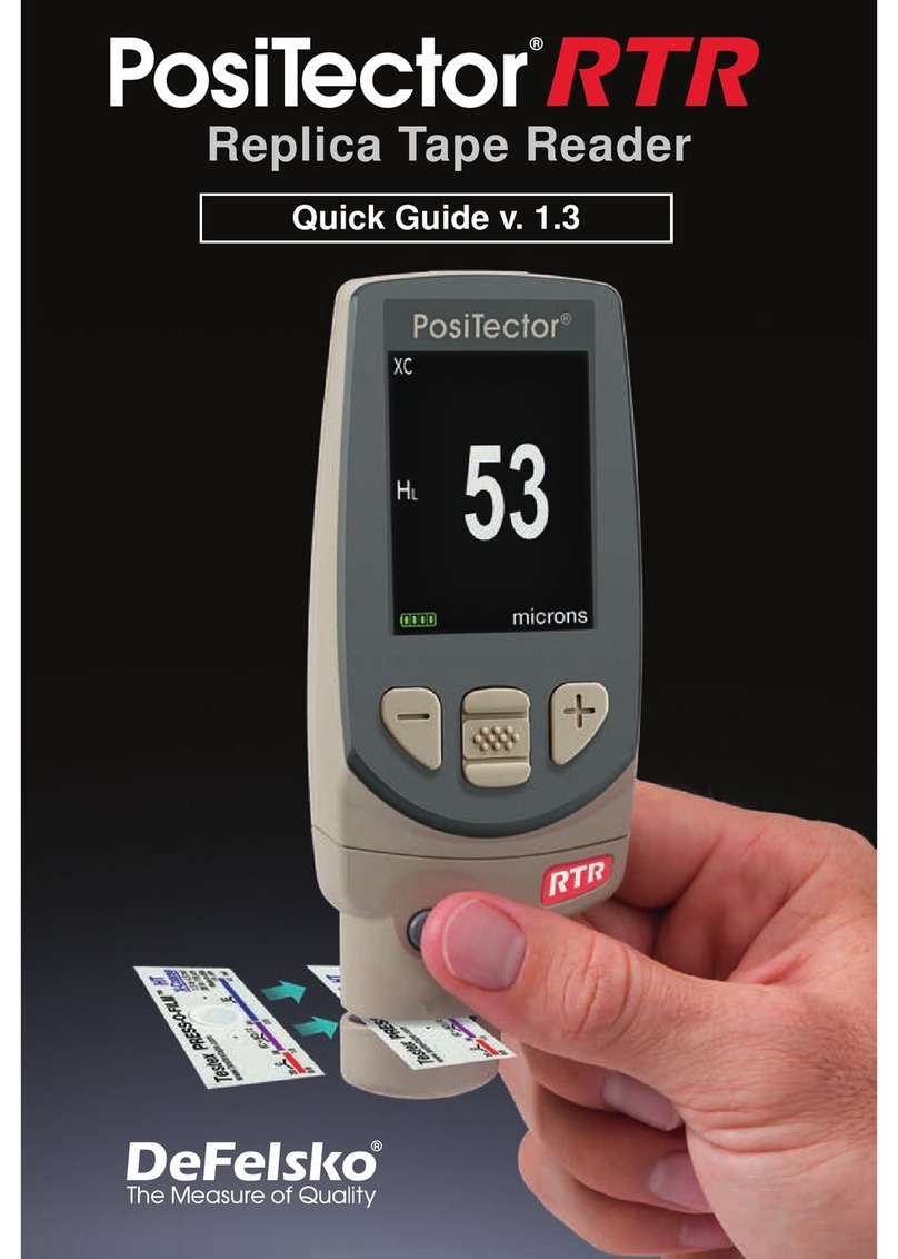
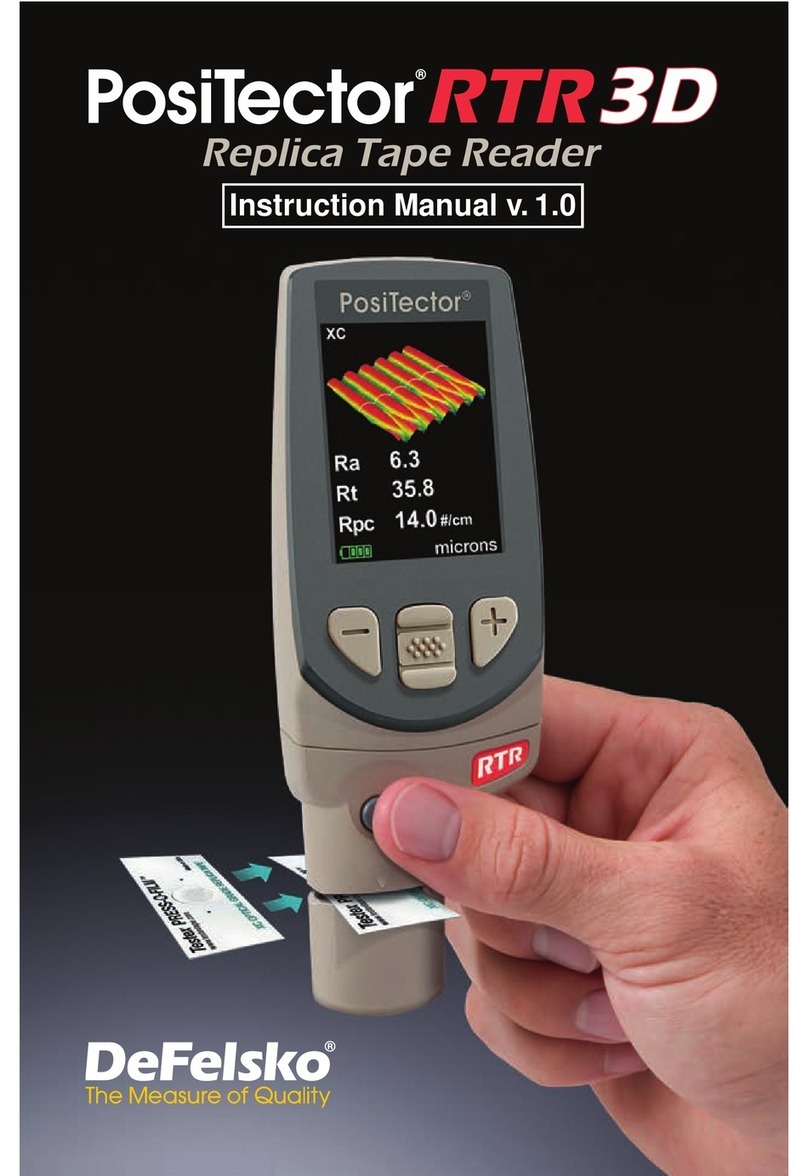
DeFelsko PosiTector RTR Series User manual

Full Guide v. 1.2
Replica Tape Reader

Introduction ......................................................... 1
Quick Start .......................................................... 2
PosiTector Body .................................................. 3
Probes ................................................................. 4
Certification ......................................................... 5
Press-O- ilm Replica Tape ................................. 7
How to Measure .................................................. 8
Cleaning the Probe Opening (Anvils) ................. 12
Calibration & Verification of Accuracy ................. 13
Menu Operation .................................................. 14
Cal Settings Menu ............................................... 15
Zero ................................................................ 15
No Tape .......................................................... 15
Tape Grade .................................................... 15
Linearize ........................................................ 16
Setup Menu ......................................................... 17
Reset .............................................................. 17
Gage Info ....................................................... 18
Peak Density .................................................. 18
2D ................................................................... 19
3D ................................................................... 19
Sound ............................................................. 21
Units ............................................................... 21
Language ....................................................... 21
Table of Contents
Table of Contents

Memory Management ......................................... 22
Standard Models ........................................... 22
Advanced Models .......................................... 23
Annotate ......................................................... 24
Display ........................................................... 25
Summaries ..................................................... 26
Screen Capture .............................................. 26
Save SD ....................................................... 27
Accessing Stored Measurement Data ................ 28
PosiSoft.net .................................................... 28
PosiSoft 4.0 Desktop Software ...................... 28
PosiTector App .............................................. 28
Connect Menu ..................................................... 29
Wi i......... ....................................................... 29
Access Point................................................... 29
USB.......... ...................................................... 31
USB Serial Streaming..................................... 31
Sync.net Now.................................................. 32
Bluetooth Smart................ ............................. 32
Bluetooth......................................................... 33
Updates .......................................................... 34
Technical Data .................................................... 36
Power Supply / Battery Indicator ........................ 36
Returning or Service ......................................... 37
Warranty .............................................................. 37

1
Introduction
Introduction
The PosiTector Re lica Ta e Reader (RTR) is a hand-held
electronic instrument that measures burnished Testex Press-O-
ilmTM replica tape to produce peak-to-valley surface profile height
measurements. It consists of a PosiTector body (Standard or
Advanced) and probe (R R-H or R R-P)
PosiTector R R-P models also measure peak density (Pd).
Advanced R R-P models generate 2D/3D images and SD
Surface Data iles.
A surface cleaned by abrasive blast is best described using two
measured parameters: eak height and eak density.
Peak Height
H – the average of the maximum peak-to-valley distances
obtained by measuring the thickness of the replica tape
HL– a more accurate peak-to-valley height measurement adjusted
for tape non-linearity without the need to average 2 or more
replicas. This method has the additional benefit of being able to
extend the range of each grade of replica tape. See Linearize
pg. 16.
Peak Density (R R P only)
Pd – the number of peaks per square millimeter or square inch.
See Peak Density pg. 18.
Measurement RTR H RTR P
Peak Height H
Linearized Peak Height HL
Peak Density Pd
2D/3D images (pg. 19) Advanced only
Save SD surface data file
(pg. 20) Advanced only

Menu peration
Menu peration
Gage functions are menu controlled. To access the Menu,
power-up the Gage, then press the center navigation button.
2
Quick Start
Quick Start
The PosiTector RTR powers-up when the center navigation
button is pressed. To preserve battery life, the Gage powers
down after approximately 5 minutes of no activity. All settings are
retained.
To ensure best accuracy, the user will be prompted to zero
the probe every time the Gage is powered-up. It is therefore good
practice to clean the probe regularly with the included cleaning
card. Cleaning is best performed when the Gage is powered down.
NOTE:
With the Gage powered down...
1. Clean the probe with the included cleaning card. (pg. 12)
2. Power-up Gage by pressing the center navigation button.
3. Zero the probe. (pg. 15)
4. Verify Gage accuracy. (pg. 13)
5. Measure the burnished replica tape. (pg. 10)
Typical Display
Current
Measurement
Unit of Measurement
thou/mils
Battery Icon
2.1
XC
HL
Tape Grade
Linearize
Mode (pg. 16)
Button Functions- Normal peration
Scroll through
Trend Charts
(Advanced only)
Access the Menu
Pause / Resume
Restore brightness
after dimming

3
USB Port
Display
PosiTector body
PosiTector body
probe connector
Wrist Strap
We recommend attaching and wearing the
supplied wrist strap.
1
2
Protective Lens Shield
The PosiTector display is covered with a thin plastic film for
protection against fingerprints and other marks during shipment.
This film, while usually removed before using the Gage, can be left
in place to protect against paint overspray or debris.
Replacements can be purchased.
connected probe type
is displayed during
power-up
PosiTector bodies accept all interchangeable probes including
surface profile (R R/SPG), coating thickness (6000/200),
environmental (DPM), Shore Hardness (SHD), soluble salt (SST),
and ultrasonic wall thickness (U G) probes.
Updates: Keep your PosiTector current with software updates
containing the latest features, functionality and probe compatibility
(see Updates pg. 34).
Power Source: 3 AAA alkaline, Lithium or optional Nickel-metal
hydride (NiMH) rechargeable batteries. or best battery indicator
results, ensure the appropriate Battery Type is selected in the
Setup > Battery Type menu (pg. 21).
The battery indicator displays a full bar with fresh alkaline
or fully charged batteries installed. As the batteries weaken, the
bar will be reduced. When the battery symbol is low
the Gage can still be used, but the batteries should be changed or
recharged at the earliest opportunity (pg. 36).

4
Additional PosiTector Probes:
The PosiTector body accepts a wide variety of probe types
including magnetic, eddy current and ultrasonic coating thickness,
surface profile, Shore hardness durometer, salt contamination and
ultrasonic wall thickness probes. See www.defelsko.com/probes
Probes
Probes
When powered-up, the PosiTector automatically
determines which probe is attached and does a
self-check.
To disconnect a probe from a body, slide the plastic
probe connector horizontally (in the direction of the
arrow) away from the body. Reverse these steps to
attach a new probe.
It is not necessary to power-down the gage when
interchanging probes.
NOTE:
Probe Connector
Button Operated
Spring Micrometer
applies constant
anvil pressure
Measurement
Opening (Anvils)
Camera
PosiTector RTR robe
(R R-P only)
(R R-P shown)
PosiTector bodies accept all PosiTector DPM, 6000, 200, SPG,
RTR, SST, SHD and UTG probes

5
A smart new way to measure!
-wirelessly connect R R-H probes to your smart device
-turn your cell phone or tablet into a virtual PosiTector gage
-includes free PosiTector app
Certification
PosiTector RTR probes include a Certificate of Calibration.
or organizations with re-certification requirements, instruments
may be returned at regular intervals for calibration.
De elsko recommends that customers establish calibration
intervals based upon their own experience and work environment.
Based on our product knowledge, data and customer feedback, a
one year calibration interval from either the date of calibration, date
of purchase, or date of receipt is a typical starting point.
PosiTector SmartLink Compatible (R R-H probes only)
R R-P probes are not compatible with PosiTector
SmartLink
NOTE:
Learn more at: www.defelsko.com/smartlink

6
Why is surface profle measurement important?
Steel surfaces are frequently cleaned by abrasive impact prior to
the application of protective coatings. The resultant surface profile
must be accurately assessed to ensure compliance with job or
contract specifications. In the protective coatings industry, replica
tape is widely used for quantifying surface profile.
Peak height and peak density are important factors in the
performance of applied protective coatings. Low values may
reduce coating bond strength (adhesion). High values may cause
peaks to receive insufficient coverage and possibly rust
prematurely and for the surface to be insufficiently wetted.
The figure below is a simplified example of why BOTH peak height
AND peak density are important to the understanding of coating
performance. The two surfaces have different geometries yet their
height measurements are the same. Peak density measurements
give a clearer picture of the surface available for bonding.
Both surfaces have the same measured peak-to-valley height. A
second important measurable parameter, peak density, helps
explain why coatings bond differently to each surface.
or these reasons, surface profile should be measured prior to
coating application to ensure that it meets contract specifications.

7
Press- -Film Replica Tape
Press- -Film Replica Tape
Press-O- ilm provides a simple way to obtain an impression of a
surface for analysis. It consists of a layer of crushable plastic micro
foam affixed to a 50.8 µm (2 mil)
incompressible polyester film. When
compressed against a roughened surface, the
foam collapses and acquires an accurate
impression, or reverse replica, of the surface.
Placing the compressed tape (replica) into the PosiTector RTR
gives a measure of the average maximum peak-to-valley height of
the surface roughness profile. The Gage automatically subtracts
the thickness of the polyester substrate from all measurements.
Press-O- ilm is available in Coarse (C) and X-Coarse (XC)
grades to accommodate measurements in different profile ranges.
ptical Grade Press- -Film Replica Tape
or improved optical resolution and to reduce optical artifacts (see
below tape comparison), this special grade of replica tape is
available for use with the PosiTector RTR-P. It provides higher
quality SD surface data files than conventional Press-O- ilm
replica tape. It is available in both Coarse (C) and X-Coarse (XC).

8
How to Measure
How to Measure
Prepare the test surface
Burnish the replica tape (create a replica)
1. Prepare the test surface
2. Burnish the replica tape
3. Prepare the Gage
4. Measure
Locate a representative site for measurement.
Clean the surface to be tested. De elsko
recommends the use of the included putty to
remove dust, debris, or residual blast media from
the surface. irmly press the putty onto the surface
using your fingers, and remove.
Ensuring a clean surface is especially important when
using the PosiTector RTR-P to measure peak density (Pd) and
generate surface images.
NOTE:
Select the appropriate grade of replica tape based on the target
profile. See tape instructions for assistance.
Pull a single adhesive-backed replica tape free of its release
paper. A “bull’s eye” circle of paper should remain on the release
paper (it is not used for measurement).
Apply replica tape to blasted surface. Press the
adhesive-backed ends of the tape to hold it firmly in
place during the burnishing process.
irmly compress the foam using the rounded end of
the included stainless steel burnishing tool. Apply
sufficient pressure in a circular and x-y rubbing
motion to produce a replica with a uniform pebble
grain appearance. Excessively hard rubbing
should be avoided because the olyester film
could become distorted. It normally takes 30 to 60
seconds to fully compress all parts of the foam on most surfaces.
After burnishing is complete, remove the replica tape from the
surface.

9
Prepare the Gage
With the Gage powered-down, clean the measurement surfaces
using the included cleaning card. Swipe the card through the
opening a few times while firmly pressing both probe buttons to
remove dust particles and residual tape adhesive.
Power-up the Gage by pressing the center navigation button. An
image appears indicating that the probe requires zeroing.
Simultaneously press and hold both probe buttons firmly
until the Gage beeps and the arrows point outward. Do
not place anything in the measurement opening during
this procedure.
Measure the included check shim to verify accuracy (pg. 13).
Ensure the correct grade of replica tape, C or XC, is displayed in
the upper left corner of the display (pg. 7).
Cleaning the anvils (pg. 12) is especially important when
using the PosiTector RTR-P to measure peak density (Pd) and
generate surface images. If the cleaning card is damp, wait for the
anvils to dry before measuring.
NOTE:

10
Measure
Insert the burnished replica tape into the
measurement opening. Ensure the tape is
properly positioned so that the burnished region
is centered within the opening in the probe with
the adhesive (sticky) side down.
To position the tape, move the tape to the back of the probe and
align the two dots (printed on replica tape) with arrows on both
sides of the measurement opening.
During measurement, a constant anvil pressure is applied to the
replica tape regardless of how hard the two buttons are pressed.
The Gage automatically subtracts the 50.8 µm (2 mil) of
incompressible polyester film. No further adjustments are required.
If you are using older tape that does not have the printed dots,
simply align by centering the tape within the measurement
opening.
PosiTector RTR-H models
1. Ensure tape is properly positioned.
2. irmly press both probe buttons simultaneously and hold until
the Gage beeps and the surface profile height (HL) measurement
is displayed. The tape can now be safely removed.

11
PosiTector RTR-P models
It is im ortant to clean the anvils before each measurement when
obtaining peak density (Pd) and generating surface images.
1. Ensure tape is properly positioned.
2.
Several images of the foam surface are
captured during each measurement.
Image blurring will occur if the tape is
touched or removed during this time.
Optical Grade Replica ape (pg. 7) provides higher quality
SD surface data files than conventional Press-O- ilm replica tape.
This special grade of tape recommended when taking
measurements which will be exported as SD images.
NOTE:
a) irmly press both probe buttons simultaneously and hold
until the Gage beeps and the arrows point outward.
b) Remove your fingers from the tape and release both probe
buttons (do not hold or remove tape from the gage).
c) Hold the gage steady while the probe measures the
compressed foam until the following graphic disappears.
3. The surface profile height (HL) measurement is immediately dis-
played. The tape can now be removed. An hour glass will dis-
play while peak density (Pd) and the associated 2D/3D images are
being generated.

12
The probe contains two measuring surfaces (anvils) that can
become contaminated with dust particles and residual tape
adhesive. It is therefore recommended to clean the probe regularly
with the included cleaning card. Cleaning is essential prior to
performing a probe zero (pg. 15) or a verification of accuracy
(pg. 13). It is best performed when the Gage is powered down.
With the Gage powered-down, swipe the card through the opening
a few times while firmly pressing both probe buttons.
The cleaning card can also be used to clean the surfaces of analog
spring micrometers. Replacement cards are available from your
dealer.
Cleaning the probe opening (anvils)
Before Cleaning After Cleaning
Cleaning the anvils is especially important when using the
PosiTector RTR-P to measure peak density (Pd) and generate
surface images.
NOTE:
Example of a 2D surface image taken with a PosiTector RTR-P
Advanced before and after cleaning the anvils with the cleaning
card.

13
Calibration
Gage calibration is typically performed by the manufacturer or
accredited lab. All probes include a Certificate of Calibration.
Calibration & Verification of Accuracy
Calibration & Verification of Accuracy
Verification of Accuracy
Ensure that the probe has been cleaned with the included
cleaning card (pg. 12) and that the probe has been zeroed
(pg. 15).
Verify accuracy of the peak height measuring system
Place the Posi ector R R Check Shim into the probe opening.
The average of several measurements should be within the
combined tolerance of both the Gage and the shim. If not, the
Gage may need to be returned to your dealer for service.
The check shim is specifically intended for all PosiTector RTR
probes. The Gage is designed to measure burnished replica tape
within a limited measuring range and automatically subtracts
50.8 µm (2 mil) from height measurements to account for the
incompressible polyester film. Therefore plastic shims intended for
other instruments such as coating thickness gages will not be
measured properly.
Verify the peak density measuring system
(R R-P models only)
Place the Peak Density Check ape into the probe opening. The
peak density (Pd) result should be within tolerance specified on
the tape. Ignore the peak height (H) result.
If not, the Gage may need to be returned to your dealer for
service.

14
Menu peration
Menu peration
Gage functions are menu controlled. To access the Menu,
power-up the Gage, then press the center navigation button.
Below is a sample menu for a PosiTector RTR H Advanced
model:
Some buttons have a tick box to their
right to indicate current status. An empty
box indicates that feature is not active.
Current selection is displayed
with darkened background
ü
Sync Now
USB Drive
Auto SYNC
Bluetooth
Wi i
Powder Probes
Updates
Exit
Press the (+) button to switch pages in a
multipage menu.
Press the (-) button to return to the previous
menu or page.
Select Exit to exit from any menu.
To navigate, use the Up and Down buttons to scroll vertically and to SELECT.
Previous Page
(Exit)
Up
Down
Next Page
Access the Menu
(Center/Select)

1515
Tape Grade
Cal Settings Menu
Cal Settings Menu
The probe should be zeroed regularly to ensure best accuracy.
While the user will be required to zero the probe every time the
Gage is powered-up. The Zero menu item allows the procedure to
be performed at more regular intervals. It is particularly useful
during long measurement sessions.
Clean the probe with the included cleaning card (pg. 12) before
performing a probe zero.
1. Select Zero from the Cal Settings menu
2. Simultaneously press and hold both probe buttons firmly until
the Gage beeps and the arrows point outward. Do not place
anything in the measurement opening during this procedure.
Zero
Selects a replica tape grade. Required when Linearize mode (HL)
is ON. C- Coarse XC - X-Coarse (default)
Simultaneously press and hold both probe buttons
firmly until the Gage beeps and displays “0”. This can be
performed from the main measurement screen without having to
access the menu.
Coarse Minus and X-Coarse Plus grades are not
supported in Linearize mode (pg. 16) since the only function of
these two grades is to improve upon the accuracy of C tape at its
low end and XC tape at its high end, something the PosiTector
RTR will automatically do when measuring HL. When Linearize
mode is O , the PosiTector RTR will measure all four grades of
replica tape just like a conventional spring micrometer.
NOTE:
SHORTCUT:
No Tape (R R-P only)
When selected the gage instructs the probe to take a picture and
store this image as a reference. This image is used with subsequent
measurements to compensate for irregularities in the optical path
within the probe. his operation is only required if the generated images
can not be cleaned up by cleaning the anvils with the cleaning card (pg. 12)

16
This is the default measurement mode. Linearize mode is ON
when this box is ticked and the "HL" appears on the display.
An undesirable characteristic of replica tape is that measurements
made with analog spring micrometers are most accurate near the
middle of each grade's range and least accurate at the outer ends
of each grade's range. That is why two other grades, Coarse
Minus and X-Coarse Plus, are used to check and, if necessary,
adjust measurements at the lower and upper ends of the primary
range of 20 - 115 µm (0.8 - 4.5 mils).
Inside the primary range, the upper end of Coarse grade’s range
and the lower end of X-Coarse grade’s range share a 38 - 64 μm
(1.5 - 2.5 mil) "overlap" region. Current Testex instructions
describe a relatively complicated and time consuming procedure
(the average of one reading using Coarse grade and one reading
using X-Coarse grade) that is used to knit the Coarse and
X-Coarse sub-ranges together to achieve reasonably accurate
readings over the primary range. This method is a compromise
between accuracy and ease of use.
When the Linearize box is NOT ticked, the PosiTector RTR
displays a height value of H comparable to the value an analog
spring micrometer would display after the 50.8 μm (2 mil) of
incompressible polyester substrate has been subtracted. In other
words, it is the average of the maximum peak-to-valley distances
obtained by measuring the thickness of the replica tape without
any correction.
When the Linearize box IS ticked, the PosiTector RTR displays
a more accurate peak-to-valley height measurement HLthat has
been adjusted for the non-linearity of replica tape. There is no
need to average 2 or more replicas from different grades of tape
AND there is no need to subtract the 50.8 μm (2 mil) of
incompressible polyester substrate. Ensure the proper tape
grade, C or XC, has been selected (pg. 7) and appears in the
upper left corner of the display.
Linearize

17
During measurement, if the linearized measurement falls outside
of the selected tape grade's range, the Gage will suggest a more
suitable tape grade to perform the measurement.
Reset
Reset (menu reset) restores factory settings and returns the Gage
to a known condition. The following occurs:
- All batches, stored measurements, images, SD surface data
files, batch names and screen captures are erased.
- Menu settings are returned to the following:
Date, Time and Wi i are not affected by either Reset.
Setup Menu
Setup Menu
NOTE:
Memory = O
Statistics = O
Peak Density* = On
Memory Display = None
Bluetooth = O
WiFi = O
2D* = O
Tape Grade = XC
Linearize = ON
3D* = O
*Posi ector R R-P models only
Units = microns
Flip Display = Normal
Sound = ON
Language = English
Battery Type = Alkaline
Backlight = Normal
USB Drive = ON
Auto Sync = O
Perform a more thorough Hard Reset as follows:
1. Power down the Gage and wait 5 seconds.
2. Simultaneously press and hold the (+) and center buttons
until the Reset symbol appears.
This returns the Gage to a known, “out-of-the-box” condition and
performs the same function as a menu Reset with the addition of:
- All calibration adjustments and Cal Memory are cleared and
returned to the Gage’s factory calibration settings.
- Bluetooth Pairing info is cleared.
- Menu settings are returned to the following:
This manual suits for next models
2
Table of contents
Other DeFelsko Card Reader manuals
