Style selections 22161-017 User manual

1
ITEM #0388008
PENDANT
MODEL #22161-017
Français p. 10
Español p. 19
ATTACH YOUR RECEIPT HERE
Serial Number Purchase Date
Questions, problems, missing parts? Before returning to your retailer, call our costomer
service department at 1-877-888-8225, 8 a.m. - 6 p.m., EST, Monday - Thursday, 8 a.m. -
5 p.m., EST, Friday.

2
PACKAGE CONTENTS
Part Description Quantity
A Fixture Body 1
B Fixture Loop 1
A
B

3
HARDWARE CONTENTS (shown actual size)
AA
Outlet Box Screw
Qty. 2
BB
Hex Nut
Qty. 2
CC
Crossbar
(Not to scale)
Qty. 1
DD
Mounting Nipple
(Not to scale)
Qty. 1
EE
Wire Connector
Qty. 3
FF
Canopy
(Not to scale)
Qty. 1
GG
Canopy Loop
(Not to scale)
Qty. 1
HH
Chain
(Not to scale)
Qty. 1
II
Twist-Lock Link
(Not to scale)
Qty. 2
JJ
Green
Ground Screw
(preassembled to
crossbar (CC))
Qty. 1
KK
Canopy Loop Ring
(preassembled to
canopy loop (GG)
Qty. 1
LL
Finial
(Not to scale)
Qty. 1

4
SAFETY INFORMATION
Please read and understand this entire manual before attempting to assemble operate or
install the product.
WARNING
• RISKOFELECTRICSHOCK-Beforebeginninginstallation,turnoffelectricityatthe
circuit breaker box or the main fuse box.
• RISKOFFIRE-Usebulbsspeciedbythemarkingsand/orlabelsonthexture.
CAUTION
• Foryoursafety,readinstructionscompletelybeforebeginninginstallation.
• Ifindoubtaboutelectricalinstallation,consultalicensedelectrician.
• Turnoffelectricitytoxturebeforereplacingthebulb(s).
PREPARATION
Before beginning assembly of product, make sure all parts are present. Compare parts with
package contents list and diagram above. If any part is missing or damaged, do not attempt to
assemble the product. Contact customer service for replacement parts.
Estimated Assembly Time: 25 - 30 minutes
Tools Required For Assembly (not included): Flathead screwdriver, Phillips screwdriver, Pliers,
Electrical tape, Wire cutters and one 60-watt max. medium-base bulb or one 13-watt max.
medium-base CFL bulb.
Helpful Tools (not included): Wire strippers, Ladder
ASSEMBLY INSTRUCTIONS
1. Threadthextureloop(B)ontothenippleattop
centerofxturebody(A)andtighten. 1
A
B

5
ASSEMBLY INSTRUCTIONS
2. Thread the (LL) onto the nipple at bottom
center of body (A) and tighten. 2
3. Install one 60-watt max. bulb or one 13-watt max.
medium-base CFL bulbs (not included). Refer to
the markings and/or labels on the for more
information.
3
HARDWARE USED LL
A
LL Finial x 1
Bulb
or

6
ASSEMBLY INSTRUCTIONS
5.a. Thread one hex nut (BB) onto top end of the
mounting nipple (DD).
5.b. Thread the mounting nipple (DD) into the center
lock hole of the crossbar (CC).
5.c. Usingpliers(notincluded),threadthehexnut(BB)
against the crossbar (CC) and hand tighten until
snug
5.d. Thread another hex nut (BB) onto the bottom end
of the mounting nipple (DD).
HARDWARE USED
BB Hex Nut x 2
DD Mounting Nipple x 1
5
DD
BB
CC
BB
4. Secure the crossbar (CC) onto the outlet box (not
included) with outlet box screw (AA). Tighten until
snug.
4
HARDWARE USED
AA Outlet Box Screw x 2
CC Crossbar x 1
CC
AA
JJ
Outlet Box
6.a. Removecanopyloopring(KK)fromcanopyloop
(GG).
1.b. Turn canopy loop (GG) onto mounting nipple (DD)
and adjust the hex nut (BB) in place and screw
down to attach to the canopy loop (GG).
1.c. Pull the supply wires through the chain (HH),
alternating links. Pull the wires through the
following components in order: canopy loop
ring(KK),canopy(FF),canopyloop(GG),and
mounting nipple (DD).
1.d. Attachxtureloop(B)andcanopyloop(GG)to
chain (HH) with twist-lock links (II).
6
BB
DD
II
HH
B
GG
FF
KK
II
HARDWARE USED
FF Canopy x 1 II Twist-Lock Link x 2
GG Canopy Loop x 1 KK Canopy Loop Ring x 1
HH Chain x 1

7
ASSEMBLY INSTRUCTIONS
7. Attachgroundxturewiretoeithergreenground
screw (JJ) screwed on crossbar (CC) or the
ground wire in the outlet box (usually GREEN or
BARE). If attaching to ground wire in the outlet
box, fasten together with a wire connector (EE)
and tightly wrap with electrical tape (not included).
ITISIMPORTANTTHEOUTLETBOXINYOUR
HOMEISPROPERLYGROUNDED.
Connect the neutral (WHITE or IDENTIFIED side)
xturewiretotheneutral(usuallyWHITE)wirefrom
the outlet box. Fasten wires together with a wire
connector (EE) and tightly wrap wire connector (EE)
withelectricaltape.Connectthehot(BLACKor
PLAINside)xturewiretothehot(usuallyBLACK)
wire from the outlet box. Fasten wires together with a
wire connector (EE) and tightly wrap wire connector
(EE) with electrical tape.
8. Push the canopy (FF) upward over the outlet box.
Threadthecanopyloopring(KK)ontothecanopy
loop (GG) and tighten until snug to secure the
canopy.
7
8
WHITE WIRE
FROM OUTLET BOX
WHITE OR IDENTIFIED
FIXTURE WIRE
BLACK WIRE
FROM OUTLET BOX
PLAIN OR BLACK
FIXTURE WIRE
BARE OR GREEN BARE OR GREEN
GROUND WIRE
FROM OUTLET BOX
FIXTURE GROUND
WIRE
BARE OR GREEN
GROUND WIRE
FROM OUTLET BOX
EE
JJ
HARDWARE USED
EE Wire Connector
JJ Green Ground Screw
x 3
x 1
GG
FF
KK
HH
II

8
CARE AND MAINTENANCE
• Wipecleanusingsoft,dryclothorstaticduster.Alwaysavoidusingharshchemicalsand
abrasivestocleanxtureastheymaydamagethenish.
WARRANTY
Themanufacturerwarrantsallofitslightingxturesagainstdefectsinmaterialsandworkmanshipforone
(1) year from the date of purchase. If within this period the product is found to be defective in material or
workmanship, the product must be returned, with a copy of the original sales receipt as proof of purchase,
in the original carton, to the place of purchase. The manufacturer will, at its option, repair, replace or refund
theoriginalpurchasepricetotheconsumer.Thiswarrantydoesnotcoverxturesbecomingdefectivedueto
misuse,accidentaldamage,improperhandlingand/orinstallationandspecicallyexcludesliabilityfordirect,
incidental or consequential damages. As some states do not allow exclusions or limitations on an implied
warranty,theaboveexclusionsandlimitationsmaynotapplytoyou.Thiswarrantygivesyouspeciclegal
rights.Youmayhaveotherrightsthatvaryfromstatetostate.
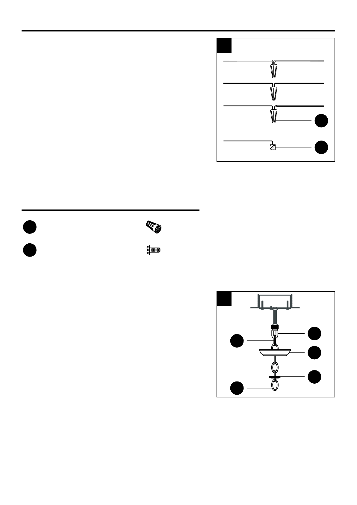
TROUBLESHOOTING
PROBLEM POSSIBLE CAUSE CORRECTRIVE ACTION
Bulbs will not light 1. Bulb is burned out.
2. Power is off
3. Faulty wire connection.
4. Faulty switch.
1. Replace light bulb.
2. Make sure power supply is on.
3. Check wiring.
4. Test or replace the switch.
Fuse blows or the
circuit breaker trips
when light is turned on.
Crossed wires or power wire is
grounding out.
Check wire connection.

9
Printed in China
Part Description Part #
B Fixture loop HSA065001
AA Outlet box screw YA0125-B
BB Hex nut YU0103-A
CC Crossbar CTA010000
DD Mounting nipple YN0050-AZM
EE Wire connector YC0004-E
FF Canopy CEA150004
GG Canopy loop CSC000001
HH Chain HCD040152
II Twist-lock link HDC022001
JJ Ground green screw YU0110-A
KK Canopy loop ring HDC020003
LL Finial MSA020001
B
A
LL
REPLACEMENT PART LIST
For replacement parts, call our customer service department at 1-877-888-8225, 8 a.m. - 6 p.m.,
EST, Monday - Thursday, 8 a.m. - 5 p.m., EST, Friday.
AA EE II
BB FF JJ
CC KK
DD HH
GG

10
ARTICLE #0388008
LUMINAIRE SUSPENDU
MODÈLE #22161-017
Numéro de série Date d’achat
Des questions, des problèmes, des pièces manquantes? Avant de retourner l’article
au détaillant, appelez notre service à la clientèle au 1 877 888-8225, entre 8 h et 18 h
(HNE), du lundi au jeudi, ou entre 8 h et 17 h (HNE) le vendredi.
JOIGNEZ VOTRE REÇU ICI

11
CONTENU DE L’EMBALLAGE
PIÈCE Description QUANTITÉ
A Corps du luminaire 1
B Anneau de suspension 1
A
B

12
QUINCAILLERIE INCLUSE (grandeur réelle)
AA
Vis pour boîte de
sortie
Qté : 2
BB
Écrou hexagonal
Qté : 2
CC
Traverse
(Pas à l’échelle)
Qté : 1
DD
Tigeletéede
montage
(Pas à l’échelle)
Qté : 1
EE
Capuchon de
connexion
Qté : 3
FF
Couvercle
(Pas à l’échelle)
Qté : 1
GG
Anneau de
couvercle
(Pas à l’échelle)
Qté : 1
HH
Chaîne
(Pas à l’échelle)
Qté : 1
II
Maillon à verrou
rotatif
(Pas à l’échelle)
Qté : 2
JJ
Vis de mise à
la terre verte
(préassemblée à
la traverse [CC])
Qté : 1
KK
Bague d’anneau
de couvercle
(préassemblée
à l’anneau de
couvercle [GG])
Qté : 1
LL
Faîteau
(Pas à l’échelle)
Qté : 1

13
INSTRUCTIONS POUR L’ASSEMBLAGE
1. Vissezl’anneaudesuspension(B)àlatigeletée
située sur la partie supérieure centrale du corps du
luminaire (A) et serrez.
1
A
B
CONSIGNES DE SÉCURITÉ
Assurez-vous de lire et de comprendre l’intégralité du présent manuel avant de tenter d’assembler,
d’installer ou d’utiliser l’article.
AVERTISSEMENT
• RISQUEDECHOCÉLECTRIQUE–Avantdecommencerl’installation,coupez
l’alimentation électrique en plaçant le disjoncteur en position hors tension ou en retirant le
fusible.
• RISQUED’INCENDIE–N’utilisezquedesampoulescorrespondantauxspécications
inscrites sur l’étiquette du luminaire.
MISE EN GARDE
• Parmesuredesécurité,liseztouteslesinstructionsavantdeprocéderàl’installation.
• Faitesappelàunélectricienqualiésivousn’êtespascertaindelamarcheàsuivrepour
l’installation.
• Éteignezleluminaireavantderemplaceruneampoule.
PRÉPARATION
Avant de commencer l’assemblage du produit, assurez-vous d’avoir toutes les pièces. Comparez
les pièces dans l’emballage avec la liste et le tableau ci-dessus. S’il y a des pièces manquantes
ou endommagées, ne tentez pas d’assembler l’article. Communiquez avec notre service à la
clientèle pour obtenir des pièces de rechange.
Temps d’assemblage approximatif : de 25 à 30 minutes
Outilsnécessairespourl’assemblage(noninclus):tournevisàtêteplate,tourneviscruciforme,
pinces,rubanisolant,coupe-letuneampouleàculotmoyend’unmaximumde60Wouune
ampouleuocompacteàculotmoyend’unmaximumde13W.
Outils utiles (non inclus) : pinces à dénuder et escabeau

14
INSTRUCTIONS POUR L’ASSEMBLAGE
2. Vissez le faîteau (LL) à la tige située sur la
partie inférieure centrale du corps du luminaire (A)
et serrez.
2
3. Vissez une ampoule d’un maximum de 60 W ou
une ampoule à culot moyen d’un
maximum de 13 W (non incluses). Consultez
les indications ou les étiquettes apposées sur le
luminaire pour obtenir d’autres renseignements.
3
Quincaillerie utilisée LL
A
LL Faîteau x 1
Ampoule
OU

15
INSTRUCTIONS POUR L’ASSEMBLAGE
5.a. Vissez un écrou hexagonal (BB) à l’extrémité
supérieuredelatigeletée(DD).
5.b. Vissezlatigeletéedemontage(DD)dansletrou
de verrouillage central de la traverse (CC).
5.c. Vissez l’écrou hexagonal (BB) à la traverse (CC)
à l’aide de pinces (non incluses), puis serrez-le
fermement à la main.
5.d. Vissez un autre écrou hexagonal (BB) à l’extrémité
inférieuredelatigeletée(DD).
Quincaillerie utilisée
BB Écrou hexagonal x 2
DD Tigeletéedemontage x 1
5
DD
BB
CC
BB
4. Fixez la traverse (CC) à la boîte de sortie (non
incluse) à l’aide des vis de boîte de sortie (AA).
Serrez fermement.
4
Quincaillerie utilisée
AA Vis pour boîte de sortie x 2
CC Traverse x 1
CC
AA
JJ
Boîte de
sortie
6.a. Retirezlabagued’anneaudecouvercle(KK)de
l’anneau de couvercle (GG).
1.b. Posez l’anneau de couvercle (GG) sur la tige
letéedemontage(DD),puisajustezl’écrou
hexagonal(BB)etvissez-ledefaçonàxer
l’anneau de couvercle (GG).
1.c. Faites passer les cordons d’alimentation à travers
les maillons de la chaîne (HH), en alternance.
Tirezleslsàtraverslescomposantessuivantes,
dans l’ordre : la bague d’anneau de couvercle
(KK),lecouvercle(FF),l’anneaudecouvercle
(GG)etlatigeletée(DD).
1.d. Fixez l’anneau de suspension (B) et l’anneau
de couvercle (GG) à la chaîne (HH) à l’aide des
maillons à verrou rotatif (II).
6
BB
DD
II
HH
B
GG
FF
KK
II
Quincaillerie utilisée
FF Couvercle x 1 II Maillon à verrou
rotatif x 2
GG Anneau de
couvercle x 1 KK Bague d’anneau de
couvercle x 1
HH Chaîne x 1

16
INSTRUCTIONS POUR L’ASSEMBLAGE
7. Fixezleldemiseàlaterreàlavisdemiseàlaterre
verte(JJ)delatraverse(CC)oujoignez-leaulde
miseàlaterredelaboîtedesortie(lhabituellement
VERTouDÉNUDÉ).Sivouschoisissezladeuxième
option,joignezlesdeuxlsàl’aided’uncapuchonde
connexion (EE) et enroulez le capuchon de connexion
(EE) de ruban isolant (non inclus) bien serré.
ILESTIMPORTANTQUELABOÎTEDESORTIEDE
VOTRE MAISON SOIT CORRECTEMENT MISE À LA
TERRE.
Raccordezlelneutreduluminaire(BLANCou
MARQUÉsurlecôté)aulneutre(habituellement
BLANC)delaboîtedesortie.Joignezlesdeuxlsà
l’aide d’un capuchon de connexion (EE) et enroulez
le capuchon de connexion (EE) de ruban isolant bien
serré.Connectezlelchargéduluminaire(NOIRou
NONMARQUÉsurlecôté)aulchargé(habituellement
NOIR)delaboîtedesortie.Joignezlesdeuxlsà
l’aide d’un capuchon de connexion (EE) et enroulez le
capuchon de connexion (EE) de ruban isolant bien serré.
8. Poussez le couvercle (FF) vers le haut sur la boîte
de sortie. Vissez la bague d’anneau de couvercle
(KK)àl’anneaudecouvercle(GG),puisserrez-la
fermementdefaçonàxerlecouvercle.
7
8
FIL BLANC
DE LA BOÎTE DE SORTIE
FIL BLANC OU MARQU
É
DU LUMINAIRE
FIL NOIR
DE LA BOÎTE DE SORTIE
FIL NON MARQUÉ OU NOIR
DU LUMINAIRE
FIL DÉNUDÉ OU VERT FIL DÉNUDÉ OU VERT
FIL DE MISE À LA TERRE
DE LA BOÎTE DE SORTIE
FIL DE MISE À LA TERRE
DU LUMINAIRE
FIL DÉNUDÉ OU VERT
FIL DE MISE À LA TERRE
DE LA BOÎTE DE SORTIE
EE
JJ
Quincaillerie utilisée
EE Capuchon de
connexion
JJ Vis de mise à la terre
verte
x 3
x 1
GG
FF
KK
HH
II

17
ENTRETIEN
• Nettoyezl’articleàl’aided’unlingedouxetsecoud’unplumeau.Évitezlesproduits
chimiquesfortsetlesnettoyantsabrasifs;ilspourraientendommagerleni.
DÉPANNAGE
PROBLÈME CAUSE POSSIBLE MESURE CORRECTIVE
Uneampoulene
s’allume pas.
1. L’ampoule est grillée.
2. L’alimentation est coupée.
3.Leslsélectriquessontmal
branchés.
4. L’interrupteur est défectueux.
1. Remplacez l’ampoule.
2.Vériezl’alimentationélectrique.
3.Vériezlecâblage.
4. Testez ou remplacez
l’interrupteur.
Unfusiblesauteou
un disjoncteur se
déclenche lorsque le
luminaire est mis sous
tension.
Deslssontcroisésouiln’yapas
de mise à la terre.
Vériezlesconnexions.
GARANTIE
Le fabricant garantit tous ses luminaires contre les défauts de matériaux ou de fabrication pour une période de
un (1) an à compter de la date d’achat. Si, durant cette période, l’article présente des défauts de matériaux ou
de fabrication, retournez-le au détaillant dans sa boîte d’origine, accompagné du reçu. Le fabricant choisira
de réparer ou de remplacer le produit, ou de rembourser l’équivalent du prix d’achat. Cette garantie ne
s’applique pas aux défauts causés par un usage inapproprié, des dommages accidentels, une manipulation
ou une installation inadéquate, et elle exclut expressément toute responsabilité pour des dommages directs,
accidentels ou consécutifs. Certains États ou certaines provinces ne permettent pas l’exclusion ou la
limitation d’une garantie implicite, de sorte que les limitations et exclusions mentionnées ci-dessus peuvent
ne pas s’appliquer à vous. Cette garantie vous confère des droits précis. Il est possible que vous disposiez
également d’autres droits, qui varient d’un État ou d’une province à l’autre.

18
Imprimé en Chine
PIÈCE DESCRIPTION NO DE PIÈCE
B Anneau de suspension HSA065001
AA Vis pour boîte de sortie YA0125-B
BB Écrou hexagonal YU0103-A
CC Traverse CTA010000
DD Tigeletéede
montage YN0050-AZM
EE Capuchon de
connexion YC0004-E
FF Couvercle CEA150004
GG Anneau de couvercle CSC000001
HH Chaîne HCD040152
II Maillon à verrou rotatif HDC022001
JJ Vis de mise à la terre
verte YU0110-A
KK Bague d’anneau de
couvercle HDC020003
LL Faîteau MSA020001
B
A
LL
AA EE II
BB FF JJ
CC KK
DD HH
GG
LISTE DES PIÈCES DE RECHANGE
Pour obtenir des pièces de rechange, communiquez avec notre service à la clientèle au
1 877 888-8225, entre 8 h et 18 h (HNE), du lundi au jeudi, ou entre 8 h et 17 h (HNE) le vendredi.

19
ARTÍCULO#0388008
LÁMPARA COLGANTE
MODELO #22161-017
ADJUNTE SU RECIBO AQUÍ
Número de serie Fecha de compra
¿Preguntas, problemas, piezas faltantes? Antes de volver a la tienda, llame a nuestro
Departamento de Servicio al Cliente al 1--877-888-8225, de lunes a jueves de 8 a.m. a 6
p.m., y los viernes de 8 a.m. a 5 p.m., hora estándar del Este.

20
CONTENIDO DEL PAQUETE
PIEZA DESCRIPCIÓN CANTIDAD
A Cuerpo de la lámpara 1
B Enganche de la lámpara 1
A
B
This manual suits for next models
1
Table of contents
Languages:
Other Style selections Home Lighting manuals

Style selections
Style selections PL1572 User manual

Style selections
Style selections 1418 Original instructions

Style selections
Style selections 18820-000 User manual

Style selections
Style selections 17783-003 User manual

Style selections
Style selections ESK/MAG/BLK/BATLED User manual

Style selections
Style selections BL-BASKETBALL User manual

Style selections
Style selections 26966-014 User manual