Planning Information
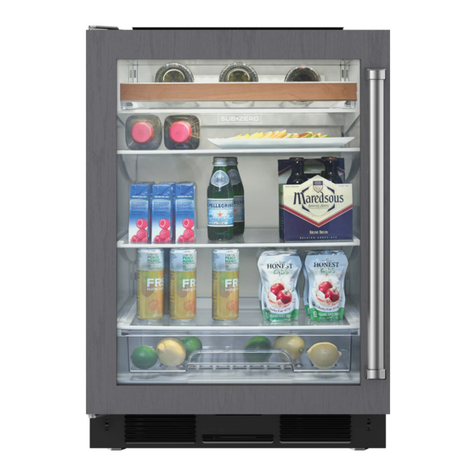
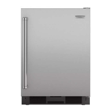
Undercounter Model UC-24C
Dimensions in parentheses are in
millimeters unless otherwise specified. 5
INSTALLATION NOTES
Refer to the illustrations and specifications
for overall dimensions, finished rough opening
dimensions and installation specifics.
For corner installations, you need allow for a
minimum 3" (76) filler so the door can open to
90˚. If you are using some larger handle
hardware, you will also need to take that into
account.
The anti-tip bracket must be installed to
prevent the unit from tipping forward.
When planning to install the Undercounter
unit next to adjoining cabinetry, you must make
provisions to allow the door to open to a
maximum of 145˚ and not interfere with the
door panel. Refer to the full-scale illustration on
page 9 for cabinetry dimensions.
For the overlay application, you will need to
provide a decorative door panel. Refer to the
overlay door panel information on page 6. You
must also supply your own handle hardware.
For the overlay application, the weight limit
for the decorative door panel is 20 lbs (9 kg).
The panel must be a minimum of 5/8"(16) thick.
Rough in the water supply line for the auto-
matic ice maker.Connect a 1/4"OD copper line
to the house supply, being sure to use an easily
accessible shut-off valve between the supply
and the unit. This shut-off valve should not be
installed behind the unit.
Donot use self-piercing valves. A saddle
valve kit (4200880) is available from your
Sub-Zero dealer. To obtain local dealer informa-
tion, visit the Locator section of our website,
subzero.com.
Aline filter is required when water condi-
tions have a high sediment content. The ice
maker operates on water pressure of 20 psi
(1.4 bar) to 100 psi (6.9 bar). In some cases a
reverse osmosis water filter system may not be
able to maintain the minimum water pressure
consistently.
A115 V AC, 60 Hz, 15 amp fused electrical
supply is required. It is recommended that a
separate circuit, serving only this appliance, be
provided.
The Model UC-24C is equipped with a power
supply cord with a 3-prong grounding plug
which must be plugged into a mating 3-prong
grounding type wall receptacle. The electrical
outlet must be placed so the grounding prong
is to the right of the thinner blades. The
outlet must be flush with the back wall. Locate
electrical within the shaded area shown in the
installation illustration on page 4.
You must follow all National Electrical Code
regulations. In addition, be aware of local codes
and ordinances when installing your service.
Refer to the Undercounter Installation
Instructions packed with the appliance, which
provides step-by-step procedures for making
sure the unit is installed properly.
