Subal SA7MK3 User manual

USER MANUAL
SONY SA7MK3
housing

Dear customer,
It is my great honor and
pleasure that you have
chosen our product.
SUBAL, one of the old-
est manufacturers
of underwater housings
and equipments, always
trying to follow new
trends and to comple-
ment its range of products. With our experience and knowledge,
for almost four decades, we cover with our quality equipment all
leading manufacturers of cameras and video cameras. The result
is that a large number of world-renowned underwater photogra-
phers uses SUBAL equipment.
I
hope that you will take some of the memorable moments with
your SUBAL!
CEO Subal
Karl Harald

4
We congratulate you on your choice of the SUBAL SA7MK3 underwater
housing for the Sony Alpha 7 III.
During the conception and design of the housing, considerable attention
was directed towards the application of advantages and unique features of the
state-of-the art Sony camera technology, making them available to the under-
water photographer.
An extensive range of high quality lens ports allows the tting of a num-
ber of interesting lenses, which is a great advantage over all other amphibi-
ous cameras available today. This will facilitate the most varied photographic
tasks.
To get the best results, to take full advantage of the system and for the pro-
tection of your camera, we recommend you take careful note of all the hints
contained in these instructions for use.
We hope you enjoy using the SUBAL SA7MK3!
GENERAL
It will be assumed that the user of the camera is fully condent and
trained in the use of diving equipment.
The demands on underwater photographic equipment are very high - pres-
sure, aggressiveness of salt water and not least, improper use results in a risk
which can only be avoided by careful handling.
Therefore assemble carefully and calmly. Check twice!
During the production process all functions and the tightness of each indi-
vidual housing are tested and checked several times. Nevertheless, we recom-
mend to test dive the housing rst without the camera tted, to ensure that
all is well.
After closing the housing, check everything as recommended on the check-
list.
After entering the water, tip the housing with the frontglass downwards and
check whether everything is watertight. Then you can dive with condence.
If the equipment has not been used for a prolonged period or perhaps after
a service (i.e a. greasing of the shafts, etc.) always test dive rst without the
camera tted.
CONTENTS
GENERAL 5
USE AND MAINTAINANCE OF O-RINGS 6
PREPARING THE CAMERA 7
MOUNTING THE CAMERA SUPPORT SADDLE 8
PREPARING THE LENS 8
OPENING THE HOUSING 8
CLOSING THE HOUSING 10
INSERTING THE CAMERA 10
THE INTERCHANGEABLE PORT SYSTEM 11
CHANGING A LENS 13
OPERATING THE FUNCTIONS 13
MOUNTING AND CONNECTING A FLASH UNIT 14
CHECK-LIST 16
GUARANTEE 17
FRONT HOUSING PART EXPLODE VIEW 19
BACK HOUSING PART EXPLODE VIEW 21
FRONT PARTS LIST 22
BACK PARTS LIST 23

6
Please take note of these points of advice:
• O-rings should be absolutely clean and be greased thinly. We recommend
the use of waterproof Silicone grease (eg. SUBAL-Silicone grease). Too
much grease results in the accumulation of small dirt particles which are
invisible.
• The sealing surfaces must be absolutely clean.
• O-rings must lie in the groove without twisting.
The equipment should be rinsed thoroughly in freshwater after each dive
in saltwater. Metal parts, especially threads (screws) should always be
greased.
Threaded parts should never be stored assembled without rst having
been cleaned and dried.
Salt residue should be removed before prolonged storage by placing in
freshwater for several days, then dried.
The O-ring of the lid and especially also the front port O-ring should be
removed.
Only use original SUBAL-spare parts and SUBAL-accessories.
Have your equipment overhauled from time to time by the manufacturer
or by an authorized service center - it is worthwhile.
USE AND MAINTAINANCE OF O-RINGS
SUBAL housings are designed to use specially formulated O-rings. Replace-
ment by other than genuine SUBAL O-rings may result in leakage. Therefore:
Use original subal O-rings only!
The most care is needed with the body O-ring and the port O-ring. Ensure
that the O-rings have no mechanical damage like cuts or at spots. If so, re-
place them immediately.
Stretching the O-ring a little and feeling it as you slide it between your
ngers is a good way of detecting abnormalities.
When closing the housing or changing the port, care should be taken that
the sealing surfaces on the housing, the O-ring grooves of the housing and the
port and the O-ring itself are absolutely clean.
Remove all dirt particles carefully to prevent water entry.
The sealing surface and the O-ring should be thinly greased with Silicone
grease. This reduces friction and abrasion and allows the O-ring to settle into
place easily.
Do not use too much grease. Undetected dirt particles could accumulate
and would lead to water entry. Take a little bit of grease on two ngers and pull
the O-ring between these ngers until it is greased all around. Wipe off excess.
The O-ring should just have a sheen.
Never use hard or sharp metal tools for putting in or removing the
O-rings. You could permanently damage the sealing surface or the
O-ring itself.
When inserting the O-ring take care that it is not twisted or is lying undulat-
ing in the groove.
The useful life of O-rings is limited in duration depending on care, fre-
quency of use and storage conditions. It is absolutely essential to change them
regularly.
Please note that the especially soft quality of the original SUBAL O-ring ma-
terial looses elasticity prematurely if it is permanently compressed. So, if you
plan not to use your housing for a long time, remove the O-ring and store it in
a cool place without deformation.
PREPARING THE CAMERA
The only thing that you should do with your camera before put it into hous-
ing is to remove rubber shield of viewnder (Fig. 1).
Knowledge and familiarization with the functions of your camera is essen-
tial to avoid mistakes when installing and using the camera. We recommend
you study your camera manual thoroughly before installing the camera.
Fig. 1 Fig. 2

8
The SUBAL New locking system levers are equipped with buttons (Fig.3) that
should be pressed before rotating them.
Do not forcefully turn the levers otherwise damage could occur.
Place the housing on a at supporting surface with the front surface of the
port downwards (Fig. 4). Push the buttons on the locking levers gently and turn
them outwards (Fig. 5, 6 & 7).
Lift the lid slowly and carefully to avoid water drips onto the camera.
Now upright the housing and pull out the camera a little bit to enable you
to remove the hotshoe connector if provided. Remove the camera.
Some big lenses have to be removed before the camera can be pulled out
of the housing.
Mounting the Camera Support Saddle
Attach the camera support saddle to the camera base with the locking lever
pointing to the camera backside. Tighten the camera screw by using a coin or
a screw driver without excessive force (Fig. 2).
Remove the plastic protection foil of the camera’s monitor!
PREPARING THE LENS
To change the focal length on zoom lenses, or for manual focusing with xed
focal length lenses, special lens gears are required which need to be tted to
the lens barrels.
Mounting the gear rings
Depending on the type of the lens, the zooming gear ring is tted onto the
lens either from the front or from the rear.
Set the zooming barrel of the lens to the mid point of the zoom range.
After noting where the zoom drive gear of the housing is located, position the
zooming gear ring on the lens in such a way that when the lens is mounted on
the camera the centre of the toothed section of the zoom gear aligns with
the zoom drive gear in the housing. Check that the gears can mesh over the
full zoom range of the lens. A nal check should be made after the camera is
inserted into the housing.
If the zooming gear ring provides marking dots t the zooming gear ring
on the lens in such a way that the markings correspond with the range of the
zoom scale.
Tighten the Nylon screws (if provided) to t the zooming gear rmly but
take care that the free-turning of the zooming ring of the lens is maintained.
Focus gear rings
The different construction of lenses requires different mounting systems
of focus gear rings. Therefore installation procedures vary. Please follow the
mounting instructions enclosed with the focus gear ring.
OPENING THE HOUSING
It is recommended to rinse the housing with fresh water and dry before
opening. When rinsing the housing make sure the port is attached properly and
ash sockets are sealed with plugs if no strobes are tted.
Fig. 3 Fig. 4
Fig. 5 Fig. 6 Fig. 7

10
CLOSING THE HOUSING
Aftercheckingthebody O-ringis clean,lubricated andproperly seatedin thegroove,
and the lid sealing surface is also clean and free from any scratches or damage, the hot-
shoe connector – if provided - is connected properly and all functions are working, the
housing lid is put on. The locking levers have to point outwards (Fig. 8).
Check now whether the lid ts
correctly and whether the gap
between the lid and the front part
seems equally spaced all around!
If the lid is lifted again after it was
put on, the O-ring might be stuck
on the lid and slide out of the
groove.
Push ends of locking levers gently and turn them inwards a quarter of a turn
until they click into place, locking them.
The locking lever must be well greased periodically (inside, on the sealing
surface area).
Check once again if the gap seems equally spaced all around!
INSERTING THE CAMERA
In order to facilitate the tting of the camera into the housing, please take
note for the following hints.
Open the housing as mentioned above and place the synch cable (hot shoe
connector if provided) over the edge of the housing, pointing outwards.
Turn the power ON/OFF switch on camera and housing to OFF position (Fig. 9
& 10).
Put the housing on the front of the port. Take the camera and align the support
saddle with the mounting rails inside the housing. Slide the camera into the housing
on the mounting rails. Lock the camera support saddle with the locking latch (Fig.
11 & 12).
Fig. 8
Fig. 10Fig. 9
Fig. 11 Fig. 12
Insert the synch cord connector in the direction indicated by the arrow on the
top of the connector into the camera hot shoe (the cable pointing into the housing).
Check the proper function of the ON-OFF control before closing the housing.
THE INTERCHANGEABLE PORT SYSTEM
For your SUBAL housing, there is a wide range of front ports available, the
largest of all manufacturers. This allows you the use of a multitude of regular
lenses under water, ranging from sheye lenses, extreme wide angle-lenses,
zooming lenses and macro lenses up to the 200 mm lens.
The port O-ring
Please pay attention to all that is advised in chapter Use and maintainance of
O-rings.
Be sure that the O-ring and the sealing surfaces are clean and lightly lubri-
cated.

12
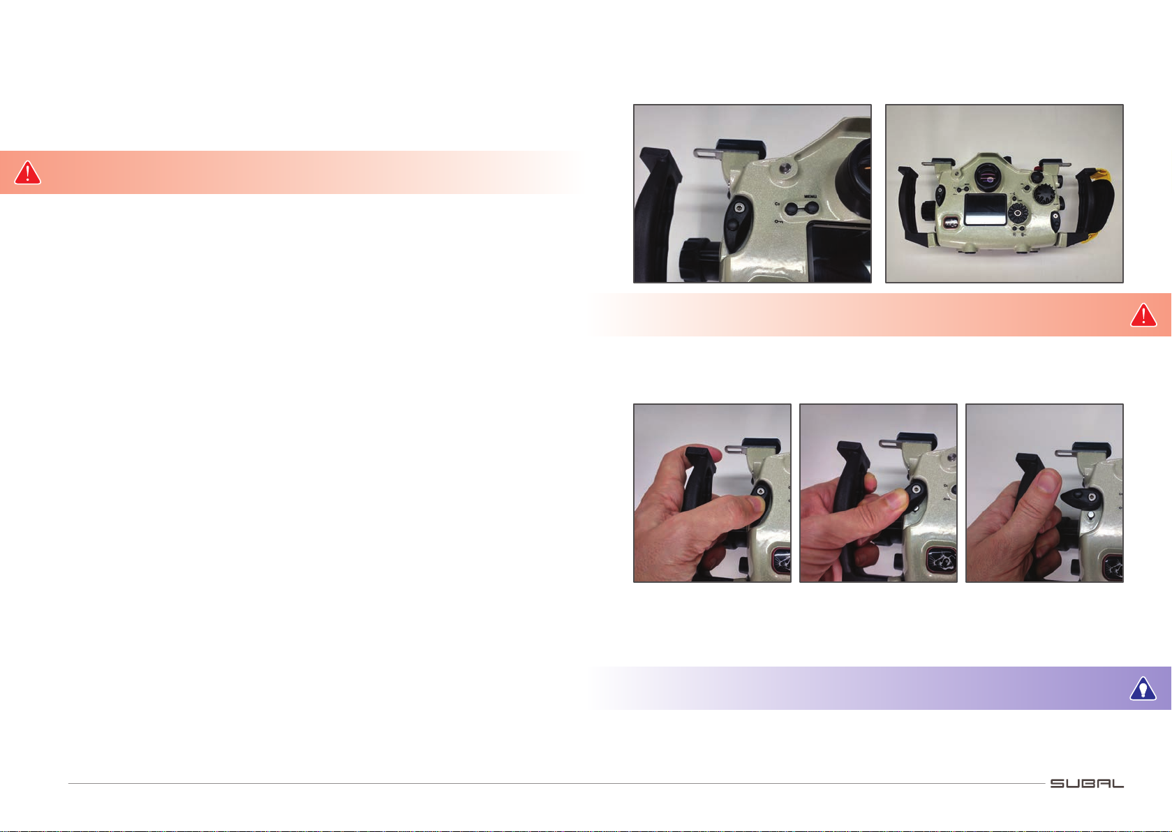
The SUBAL SA7MK3 with port size 3 provides a port locking system. Press
the port lock button to release the port lock. After mounting the port, it will
lock itself.
Inserting of the frontport
SUBAL-frontports are attached to the housing by a bayonet mount.
Insert the port (after checking as described above) into the housings bayo-
net with the white dot or the SUBAL-logo pointing towards the front main dial
control knob.
When pushed in, turn the port 90° clockwise until it stops. If properly in-
stalled, the white dot or the SUBAL-logo is aligned with the middle of the housing.
After installing check thoroughly that the O-ring is seated correctly in its
groove and does not protrude from the housing.
To remove the port turn counter-clockwise until it stops and then turn back
a little bit.
Do not change the port if it is very warm (eg. through irradiation from the
sun, etc.)!
Synthetic material from which the ports are made expand more than the
aluminium housing body and may therefore jam in the mounting.
When travelling by aircraft the frontport should be left mounted to the
housing ONLY if the port O-ring and/or the body O-ring is removed.
Cleaning the front glass
The front glass of the ports are to be cleaned carefully to avoid scratches.
If possible, rinse well in freshwater, let it drip off and dry carefully with a soft
cloth. Dried lime/salt spots are very hard to remove!
Faint scratches are lled in by the water and stay invisible but with greater
damage, it may be necessary to replace the front glass.
Domeports
Domeports are ports with a curved front glass. They are mainly used with
wide angle lenses to keep the same angle of coverage under water as on land.
When using domeports for wide angle lenses, please note the following:
• Dome glasses act in water like lenses, creating an apparent image of the
actual subject, which is smaller and closer than in reality.
• The lens must be focused on this virtual image.
• The required adjustment of the lens is in the region of 0.15 to 0.3 m, de-
pending on the curvature of the dome.
• A dioptre lens on the camera lens restores the full focusing range under
water.
• The required power of the dioptre lens depends on the lens type and the
type of the domeport. Without these correcting lenses you may not even
be able to get your subject in focus!
• The fogging of the front glasses can be avoided by inserting Silicagel or by
applying an antifogging liquid.
CHANGING A LENS
SUBAL SA7MK3 allows changing the lens without camera removal.
• Unlock the Port Lock.
• Remove the frontport.
• Push the lens release button to release the lens lock mechanism.
• Turn the lens clockwise to remove it.
• Leave the lens release button, put the new lens onto the camera and at-
tach the proper port.
OPERATING THE FUNCTIONS
The operation of the camera functions is the same as for surface use: By
pressing the corresponding levers, push buttons or turning of the knobs.
If illumination of the subject is insufcient to guarantee proper autofocus
operation, additional lighting has to be used (pilot light of ash unit, etc.) or
the camera has to be switched over to manual focus.
Therefore a focus gear is required (not possible with all lenses).
Autofocus mode
If the subject in the picture is out of focus, there are a number of methods
available for restoring sharpness:
• Adjust the focus by pressing the shutter release lever slightly until AF
activates, keep it half pressed while you compose the picture and shoot.

14
• Adjust the focus by pressing down the shutter release lever slightly until
AF activates. Now press the AF-lock lever (the shutter release lever now
can be left) and keep it pressed until you have chosen the wanted frame
and have shot your photo.
• Choose the point of autofocusing with the Focus Area Selector.
Manual focusing operation
To adjust focus manually a focus gear ring on the lens is required.
Please note the mounting instructions enclosed with the focus gear ring.
The crown wheel inside the housing and the focus gear on the lens have to mesh.
MOUNTING AND CONNECTING A FLASH UNIT
The SUBAL SA7MK3 is equipped with 2 ports to connect Sea&Sea ber optic
cables. Adapters for other systems (e. g. INON) are available as accessories.
Modern strobes with STTL function provide full TTL control!
Optionally a built in ash electronic with up to max. 3 strobe sockets is
available. This can be upgraded by your local dealer.
A wide range of perfected strobearms are available for the combination of
a SUBAL SA7MK3 housing and strobes on the market (Sea & Sea, INON, etc.).
The arms are fastened by pushing them onto an adapter plate on the up-
per part of the housing. The swivel arm is secured by screwing the footscrew
into the center indentation of the adapter plate. For handheld ash operation
(point and shooting), the screw needs only to be unscrewed a little and the
ash unit removed fortlessly and quickly and can be freely guided.
For other ash arms (eg. Nikonos, Sea & Sea etc.) adapters are available
which allow the mounting of the corresponding swivel arms by use of trays
(please see accessories).
We also provide a Nikonos 5 pin strobe bulkhead, or S6 or Ikelite Bulkhead
for it as accessories.
When inserting the ash unit plug, please take care:
• The socket must be free of dirt, sand and moisture.
• The plug O-ring, too, has to be checked carefully for cleanliness and
should be lightly greased.
• Note the position of the indexing key and groove and push the plug into
the socket without using force, to avoid damage to the contact pins.
• The plug should be pushed in a few millimeters into the socket by hand and
only then the knurled screw screwed into the socket and slightly tightened.
In order to guarantee proper ash control, the contacts should be carefully
protected from oxidation.
When removing the ash unit from the camera housing, proceed as follows:
While removing the knurled screw, hold the equipment in such a way that
the socket and plug point downwards. This allows the water which is in front
of the O-ring to drip off. Then pull the plug out slowly, so that the suction ef-
fect is as light as possible and no water gets into the contacts. If water has
penetrated, it has to be removed by blowing it out and drying. Contact prepa-
rations (sprays) are recommended from time to time.
SUBALTTL-cables have a triple sealed, Nikonos-compatible plug, which pre-
vents water penetrating into the thread of the socket.
The Nikonos, S6 and Ikelite bulkheads are not waterproof with the plug
removed.
The red blanking plug must be screwed into the socket(s) if the housing is
used without ash unit(s).

16
CHECK-LIST
• After ensuring that the main O-ring has been installed and the housing
closed properly, please check carefully ONCE AGAIN, whether:
• The gap between the housing front and the lid seems equally spaced
all around.
• The gap between the housing front and the port seems equally spaced
all around and the O-ring has not been squeezed out.
• The shutter release lever works easily.
• All functions work properly.
• The ash plug(s) are plugged in correctly and tightened and the outside
O-ring has not been squeezed out.
• If no ash is used the red plugs must be screwed in.
• The lens cap is removed from the camera lens.
• The frontglass of the port is clean, inside & out.
GUARANTEE
Duration of guarantee:
SUBAL SA7MK3 underwater housings are guaranteed against defects in ma-
terial or workmanship for two full years from date of purchase for consumer
use. Housings used commercially are guaranteed for 90 days. The invoice or
receipt is valid as guarantee certicate. Keep it safe.
Conditions of warranty:
The guarantee extends without exception to the rectication of material
and production faults of goods manufactured by SUBAL Austria. Faulty parts
are exchanged or repaired at the option of the manufacturer. No further claim
is possible. Pre-requisite for the right to claim is impeccable care and use of
the unit.
No guarantee claim will be accepted without the prior consultation and
authorisation of the manufacturer and must be returned freight paid. The
guarantee is void after intervention, repair or modication by non authorised
persons.
In order to check for transport damage, we recommend that newly deliv-
ered units be water tested without the camera or ash unit tted.
Repairs:
The unit must be returned freight prepaid to SUBAL Austria or any other
SUBAL partner.

18
FRONT HOUSING PART EXPLODE VIEW
24
17
20 23 5 13 2 21 11
26712
3
19810 9141161815
4
25
6
29
material
Thermal treatment
Mass
ratio
Part name
Part number
Sheet size
Changes
Date
Name
Date
Aprov
Stand.
Goran Limić
9/4/2018
1 - Ass-Sony Alpha 7MK3-VT
A3
1:10
Kneginje Zorke 73/5
11000 Beograd
Engin.
Sheet num.
2
27

20
BACK HOUSING PART EXPLODE VIEW
17 6 20 21 15 1 22 23 5 13 12
16
4
2418911103
2
8
7
19
material
Thermal treatment
Mass
ratio
Part name
Part number
Sheet size
Changes
Date
Name
Date
Aprov
Stand.
Goran Limić
9/4/2018
2 - Ass-Sony Alpha 7MK3-RT
A3
1:5
Kneginje Zorke 73/5
11000 Beograd
Engin.
Sheet num.
2

22
BACK PARTS LIST
ITEM
NO. PART NUMBER QTY.
1 Sony Alpha 9-VT V1(EK-SA9-VTV1) 1
2 Ass-Sony Alpha 9 - On-Off 1
3 Ass-Sony Alpha 9 - Triger 1
4Ass-Sony Alpha 9 - Preview Button 1
5 Ass-Sony Alpha 9 - Mode Dial 1
6Ass-Sony Alpha 9 - Fokussierung 1
7 Ass-Sony Alpha 9 - Front Dial Axle 1
8Ass-ND80-Zwischenkegelrad 1
9 Ass-Sony Alpha 9 - Front Dial 1
10 Ass-Sony Alpha 9 - Front Dial Wheel 2 1
11 Ass Bajonettring ABRG52 1
12 Ass-Sony Alpha 9 - Portverriegelung 1
13 Ass- GK Drucktaste mit Kappe 15.5 2
14 Ass - Sony Alpha 7MK3 - Kameraschlitten 1
15 Sony Alpha 7MK3 - Camera Holder (EKSA7MK3-CH) 1
16 Ass Leiterplatte 1
17 Ass-Sony Alpha 7MK3 - POM Cover 1
18 Ass-Schlossplattenkomponente left 1
19 Ass-Schlossplattenkomponente right 1
20 ASS-Blindstopfen M14x1 POM 3
21 Ass_LED vom Leckwarner 1
22 Ass_Sea+Sea Fassung 2
23 Ass - Z-Auage 1
24 Ass-T-Platte rechts 2
25 Ass_Handgriff-links 1
26 Ass-Handgriff-rechts 1
27 Bumpon Elastikpuffer 3M d19 x 4 (EK-610169) 2
ITEM
NO. PART NUMBER QTY.
1 Sony Alpha 9-RT V1 (EK-SA9-RTV1) 1
2 Ass-Sony Alpha 9 - Exposure Compensation Dial 1
3 Ass-Sony Alpha 9 - Rear Dial Wheel 1
4Ass-Sony Alpha 9 - AEL 1
5 Ass-Sony Alpha 9 - Rear Dial 1
6 Ass KK Drucktaste Schlitzbuchse mit Ausleger 8 2
7 Ass- GK Drucktaste mit Kappe 9 1
8Ass KK Drucktaste Schlitzbuchse mit Ausleger 9 1
9 Ass KK Drucktaste Schlitzbuchse mit Ausleger 7 2
10 Ass Multy jog Main axle 1
11 MJ - Jog outside (EKMJ-JO-V2) 1
12 MJ - Driver inside for SA7MK2 V1(EK-MJ-DISA7MK2V1) 1
13 Spring 1
14 OR14-2 1
15 SSA7 Display window (EK-SSA7-DISWI) 1
16 Ass-Sony Alpha 9 - REC 1
17 Ass_Riegel-links 1
18 Ass_Riegel-rechts 1
19 Ass-Standard-Sucheroptik-ND700 Tubus 1
20 Ass-Sony Alpha 7MK3 - Axle for Hole Closing 1
21 Ass-Sony Alpha 7MK3 - Axle for Hole Closing Short 1
22 Sticker Back Side 2 1
23 Sticker Back Side 1
24 Bumpon Elastikpuffer 3M d19 x 4 (EK-610169) 1
FRONT PARTS LIST

Subal GmbH
Schulgasse 2
1180 Wien
Tel: +43 1409 5897
E-Mail: [email protected]
Construction & Engineering - Steyr
Palais-Werndl
Schönauerstr 7
4400 Steyr
Tel: +43 7252 464 24
© 2018.
Table of contents
Other Subal Camera Accessories manuals