Subaru ROBIN RGD3300H User manual

SERVICE
MANUAL
RGD3300H
RGD5000H
GENERATORS
Models
PUB-GS2380
Rev. 06/08


CONTENTS
Section Title Page
1. SPECIFICATIONS ................................................................................. 1
2. PERFORMANCE CURVES.................................................................. 2
3. GENERAL DESCRIPTION
3-1 External View................................................................................... 3
3-2 Control Panel................................................................................... 4
3-3 Serial Number and Specification Number........................................ 4
4. CONSTRUCTION AND FUNCTION
4-1 Construction .................................................................................... 5
4-2 Function........................................................................................... 5
4-3 Generator Operation........................................................................ 9
5. SAFETY PRECAUTIONS..................................................................... 12
6. RANGE OF APPLICATIONS ............................................................... 13
7. MEASURING PROCEDURES
7-1 Measuring Instruments .................................................................... 16
7-2 AC Output Measuring ...................................................................... 17
7-3 Measuring Insulation Resistance..................................................... 18
8. CHECKING FUNCTIONAL MEMBERS
8-1 AC Receptacles ............................................................................... 19
8-2 Circuit Breaker ................................................................................. 19
8-3 Stator ............................................................................................... 20
8-4 Rotor Assembly ............................................................................... 20
8-5 Condenser ....................................................................................... 21
8-6 Diode Rectifier ................................................................................. 22
9. DISASSEMBLY AND ASSEMBLY
9-1 Preparation and Precautions ........................................................... 23
9-2 Special Tools for Disassembly and Assembly ................................. 23
9-3 Disassembly Procedures................................................................. 24
9-4 Assembly Procedures...................................................................... 33
9-5 Control Box...................................................................................... 42
10. TROUBLE SHOOTING
10-1 No AC Output .................................................................................. 43
10-2 AC Voltage is Too High or Too Low.................................................. 45
10-3 AC Voltage is Normal at No-load, but the Load Cannot be Applied. 46
10-4 No DC Output .................................................................................. 47
11. WIRING DIAGRAM ............................................................................... 48
GENERATOR_GS2380.fm 0 ページ 2007年10月1日 月曜日 午前9時13分
– 1 –
1. SPECIFICATIONS
Specifications are subject to change without notice.
Model RGD3300H RGD5000H
GENERATOR
Type Brushless, self-exciting, 2-poles, single phase
Voltage regulator Condenser type
AC output
Frequency (Hz) 60
Rated voltage (V) 120, 120/240
Rated output (VA) 3000 4500
Maximum output (VA) 3300 5000
DC output (V-A) 12-8.3
Power factor 1.0
Over current protector No-fuse Breaker
Noise level at rated output (dB-7 m) 77.5 79.7
ENGINE
Model 1B30 1B40
Type Air-cooled, 4-cycle, single cylinder diesel engine
Displacement (ml) [cu. in.] 347 [21.17] 462 [28.19]
Fuel Automobile diesel light oil
Fuel tank capacity (L) [US gal.] 12.0 [3.17]
Continuous operating hours at rated output (h) 8.5 5.9
Starting system Electric and Recoil starter
Dimensions L × W × H (mm) [in.] 790 × 515 × 576 [31.10 × 20.28 × 22.68]
Dry Weight (kg) [lb] 87 [191.8] 104 [229.3]
GENERATOR_GS2380.fm 1 ページ 2007年10月1日 月曜日 午前9時13分
– 2 –
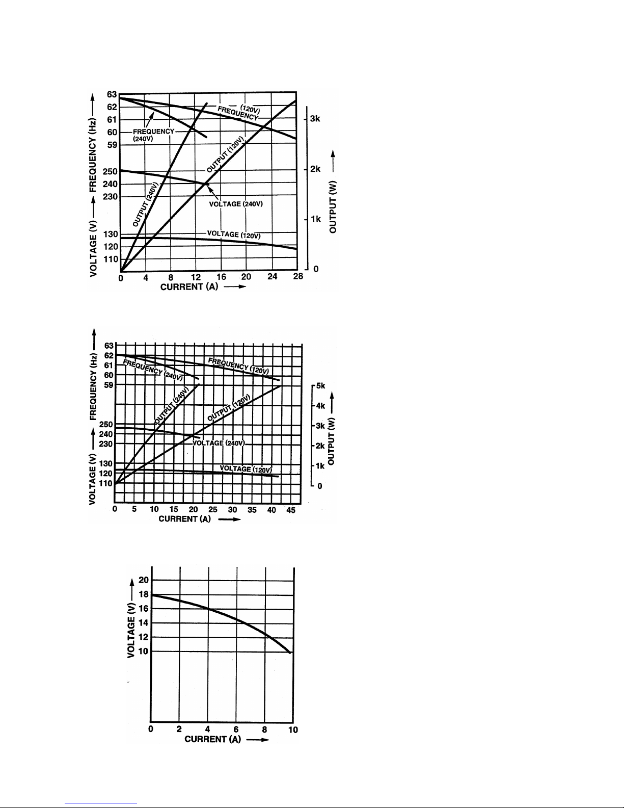
2. PERFORMANCE CURVES
2-1 MODEL RGD3300H
RGD3300H
Output Max............................3300 W
Rated .........................3000 W
Frequency .................................60 Hz
Voltage ...................................... 110 V
2-2 MODEL RGD5000H
RGD5000H
Output Max............................5000 W
Rated .........................4500 W
Frequency .................................60 Hz
Voltage ...................................... 110 V
2-3 DC OUTPUT (RGD3300H, RGD5000H)
DC Voltage ..................................12 V
DC Ampere ................................8.3 A
DC Output ................................100 W
The voltage curve shown in the left indi-
cates the characteristic of DC output when
charging a battery.
The voltage may be decreased by 20%
when the resistance load is applied.
NOTE: It is possible to use both DC and
AC outputs simultaneously up
to the rated output in total.
GENERATOR_GS2380.fm 2 ページ 2007年10月1日 月曜日 午前9時13分

– 3 –
3. GENERAL DESCRIPTION
3-1 EXTERNAL VIEW
FUEL COCK
AIR CLEANER
RECOIL STARTER
RECOIL STARTER HANDLE
FUEL GAUGE TANK CAP
FUEL TANK
CONTROL PANEL
OIL GAUGE (OIL FILLER)
SPEED ADJUSTER
OIL FILTER
OIL DRAIN PLUG
FUEL FILTER
ELECTRIC STARTER
MUFFLER
GENERATOR_GS2380.fm 3 ページ 2007年10月1日 月曜日 午前9時13分
– 4 –
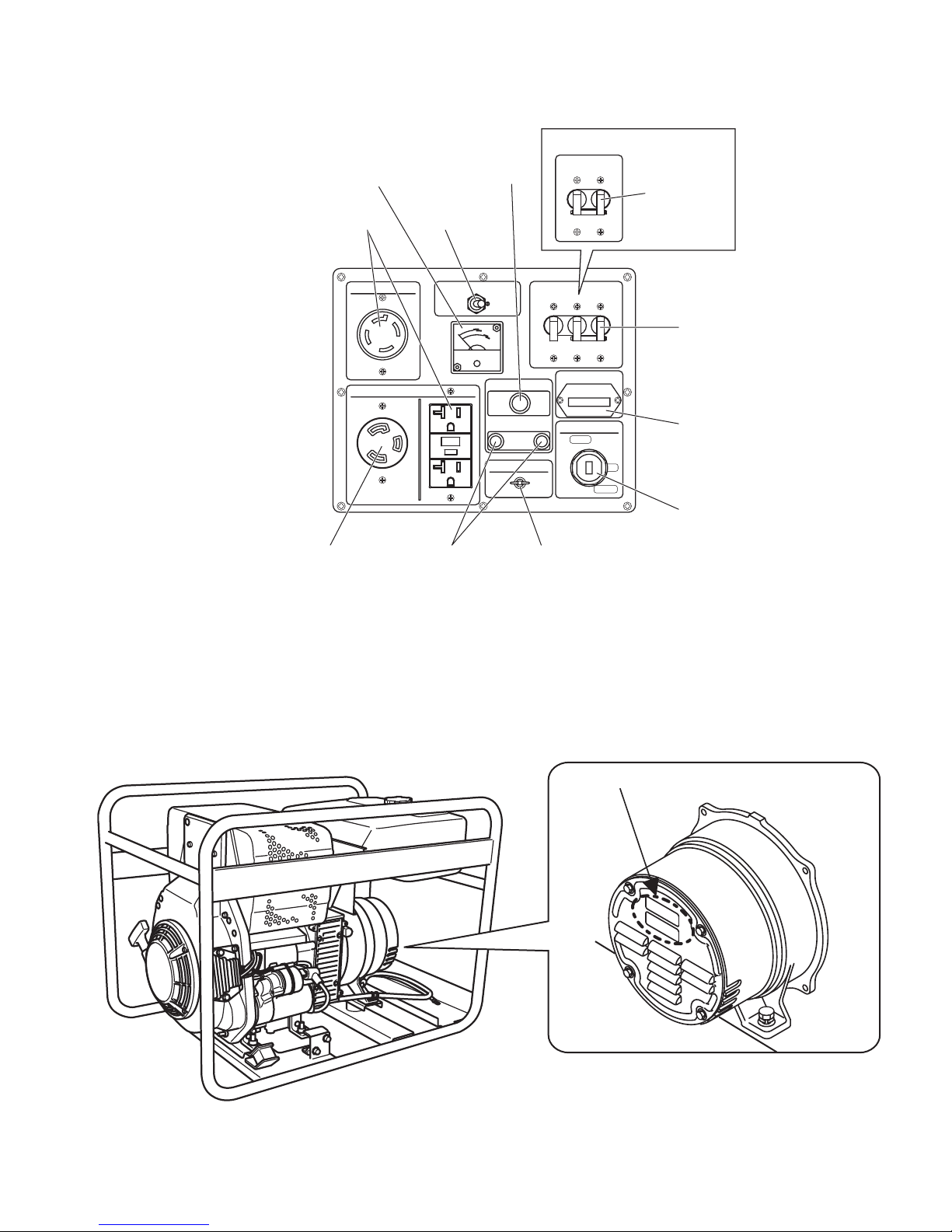
3-2 CONTROL PANEL
●RGD3300H/5000H: 60 Hz-120 V, 240 V TYPE
3-3 SERIAL NUMBER AND SPECIFICATION NUMBER
Serial number and Production number are indicated on the labels stuck on the rear cover.
Specification label is attached on the frame.
NOTE: Always specify these numbers when inquiring about the generator or ordering spare parts
in order to get correct parts and accurate service.
RGD3300H
AC RECEPTACLES (20 A)
VOLTMETER
FULL POWER
SWITCH
AC CIRCUIT
BREAKER
DC FUSE
HOUR METER
KEY SWITCH
GROUND TERMINAL
DC TERMINALS
AC CIRCUIT
BREAKER
AC RECEPTACLES (30 A)
PROD No. / SER No. (Label)
GENERATOR_GS2380.fm 4 ページ 2007年10月1日 月曜日 午前9時13分

– 5 –
4. CONSTRUCTION AND FUNCTION
4-1 CONSTRUCTION
4-2 FUNCTION
4-2-1 STATOR
The stator consists of a laminated silicon steel
sheet core, a main coil and a condenser coil which
are wound in the core slots.
The condenser coil excites the rotor field coil which
generates AC voltage in the main coil.
GENERATOR BASE
MOUNT RUBBER
STARTOR BOLT
REAR COVER
THROUGH BOLT
FRONT COVER
END COVER
BALL BEARING
STARTOR COMPLETE
SUPPORT RING
ROTOR COMPLETE
GENERATOR_GS2380.fm 5 ページ 2007年10月1日 月曜日 午前9時13分

– 6 –
4-2-2 CONDENSER
Two condensers are installed in the control box and
are connected to the condenser coil of the stator.
These condensers and condenser coil regulate the
output voltage.
4-2-3 ROTOR
The rotor consists of a laminated silicon steel sheet
core and a field coil which is wound over the core.
DC current in the field coil magnetizes the steel
sheet core. Two permanent magnets are provided
for the primary exciting action.
A diode rectifier and surge absorber is mounted inside of the insulator.
DIODE RECTIFIER SURGE ABSORBER
GENERATOR_GS2380.fm 6 ページ 2007年10月1日 月曜日 午前9時13分

– 7 –
4-2-4 FUSE
The 10 ampere DC fuse mounted on the control
panel protects whole DC circuit from getting dam-
age by overload or short circuit.
4-2-5 NO-FUSE BREAKER
The no-fuse breaker protects the generator from getting damage by overloading or short circuit in the
appliance. The table below shows the capacity of no-fuse breaker by each spec. and their object of pro-
tection.
MODEL SPECIFICATION NO-FUSE BREAKER OBJECT of PROTECTION
RGD3300H 120/240 V 14 A × 2 Total output amperage
RGD5000H 120/240 V 20 A × 2 Total output amperage
30 A Output from 30 A receptacle
GENERATOR_GS2380.fm 7 ページ 2007年10月1日 月曜日 午前9時13分
Other manuals for ROBIN RGD3300H
1
This manual suits for next models
1
Table of contents
Other Subaru Inverter manuals


