Subject Link RPT-2012G/GP-4F-T Instructions for use

Industrial Managed Ethernet Switch Hardware User Manual
RPT-2012G/GP-4F-T
Quick Installation Guide
Version 1.0.0
Subject Link Inc
9F-1, No. 77, Sec 4., Nangjing E.
Rd, Taipei City, 10580, Taiwan,
R.O.C.
Tel: +886 935 672 398
Mail: [email protected]
Web: www.sbjlink.com

Contents
Overview ...........................................................................................................................................................1
Package Check List...................................................................................................................................1
Hardware Description..................................................................................................................................2
Front Panel Instruction ..........................................................................................................................2
Dimensions..................................................................................................................................................2
Top View ......................................................................................................................................................3
LED Instruction ..........................................................................................................................................3
Reset Button...............................................................................................................................................4
USB Port .......................................................................................................................................................4
Earth Grounding........................................................................................................................................4
Hardware Installation...................................................................................................................................5
SFP Cabling.................................................................................................................錯誤! 尚未定義書籤。
Wiring Power Inputs ...............................................................................................................................6
Wiring Fault Alarm...................................................................................................................................6
Wiring Digital Inputs................................................................................................................................6
Double-Secure Power Input Fault Alarm........................................................................................7
Mounting .....................................................................................................................................................8
Installation Steps......................................................................................................................................9
Specification.................................................................................................................................................. 10

1
Overview
This user manual is for "RPT-2012G" and "RPT-2012G-T", where "-T" refers to the extended
temperature (-40°C ~ 75°C (-40°F ~ 167°F)) that is supported. This is an industrial managed gigabit
PoE+ Ethernet switch with the following hardware features:
Interface
▪MDI/MDI-X function supported on all copper ports
▪Embedded 8x Gigabit Ethernet ports with 30W PSE + 4x 1000 SFP Slot
▪Store-and-forward switching architecture
Switch Properties
▪Up to 16K MAC Address Table supported
▪Up to 9216bytes Jumbo Frame supported
▪Up to 12Mbits Packet Buffer supported
Power Input
▪Redundant 48-57VDC power
Temperature
▪Standard operating temperature: -10°C ~ 60°C (14°F ~ 140°F)
▪Extended operating temperature: -40°C ~ 75°C (-40°F ~ 167°F)
▪Storage temperature: -40°C ~ 85°C (-40°F ~ 185°F)
Mechanical Construction
▪Class IP30 protection
▪DIN-Rail Mounting, Optional Wall Mounting
PACKAGE CHECK LIST
The "RPT-2012G(-T)" is shipped with the following items. Ensure that all the items are in the
box. If any item is missing or damaged, contact us for assistance.
▪RPT-2012G/GP-4F(-T) switch x 1
▪Protective caps for 8x copper ports, 4x SFP slots, 1x USB port, and 1x RJ45 console port
▪Wall mount brackets and screws (Optional)
▪RJ45 to RS232 Serial console cable x 1

2
Hardware Description
FRONT PANEL INSTRUCTION
The following picture is the front panel for "RPT-2012GP-4F(-T)".
DIMENSIONS
WxHxD: 72x145x118 mm

3
TOP VIEW
This is the top view of the RPT-2012GP-4F(-T)
containing the ground, power inputs, and fault
alarm relay.
LED INSTRUCTION
System LEDs
LED
Color
Status
Description
PWR1
Green
On
Power is supplied on the power input 1.
Off
Power is not supplied on the power input 1.
PWR2
Green
On
Power is supplied on the power input 2.
Off
Power is not supplied on the power input 2.
Fault
Green
On
The system boots up and in normal operation.
Off
The system is powered off or during booting.
Red
On
The configured event of failure is triggered.
RM
Green
On
This device has the Ring Master.
Off
The Ring Master is not on the device.
Ring
Green
On
The Ring protocol is enabled and works normally.
Flashing
The Ring protocol is enabled, but works abnormally.
Off
The Ring protocol is disabled.
Interface Status LEDs
LED
Color
Status
Description
SFP Slot
P9 to P12
(1000M)
Green
On
The 1000Mbps link of the fiber port is active.
Flashing
Data is transmitted on the fiber port at 1000Mbps.
Off
The 1000Mbps link of the fiber port is inactive.
LAN Port
P1 to P8
(1000M)
Green
On
The 1000Mbps link of the port is active.
Flashing
Data is transmitted on the port at 1000Mbps.
Off
The 1000Mbps link of the port is inactive.
LAN Port
P1 to P8
(10/100M)
Amber
On
The 10/100Mbps link of the port is active.
Flashing
Data is transmitted on the port at 10/100Mbps.
Off
The 10/100Mbps link of the port is inactive.

4
PoE+
P1 to P8
Amber
On
An IEEE 802.3at/af powered device is connected.
Flashing
PoE overload or power budget exceeded.
Off
No IEEE 802.3at/af powered device is connected.
RESET BUTTON
A multifunctional reset button is provided. Use a pointed object such as toothpick or paper clip
(straightened) to press the reset button.
Continuous
Seconds
Action
1
Save the running configuration to the USB device named "running-config".
4
Reboot the system.
More than 7
Reset the system to factory default and reboot it.
USB PORT
A USB port is available on the switch that is located between the Console port
and Reset button. This USB port provides the following features:
▪Backup/Restore Configurations
▪Auto-Load configuration from USB
▪Auto-Backup configuration to USB
▪Save system logs to USB
EARTH GROUNDING
The earth grounding and cautious wire routing are helpful to suppress the effects of noise from
electromagnetic interference (EMI). The switch has to be installed on a well-grounded surface, for
instance, a metal panel.
The location of earth ground screw is usually near the location of power
inputs, for example:
▪Top side for most of din-rail models
▪Rear side for most of rack-mount models
▪Front side for most of M12 models
Note: Connect the ground from the ground screw to the surface of ground before wiring the
power inputs.

5
Hardware Installation
Insert SFP Module
1. Insert the SFP module. A triangle is available on the switch and SFP module.
2. Push the SFP module down.
Remove SFP Module
1. Press and remove the SFP cable.
2. Open the SFP module and remove it.
6
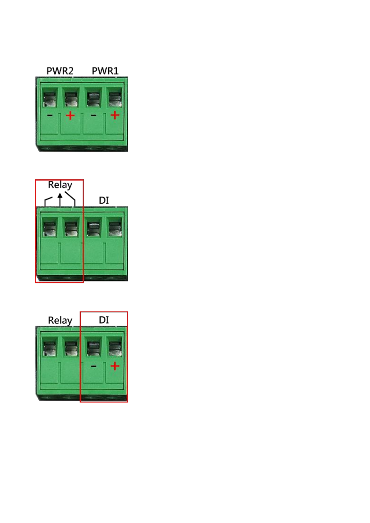
WIRING POWER INPUTS
1. Insert the positive and negative wires into the PWR1 (+,-) and
PWR2 (+,-) on the 4-contact terminal block connector.
2. Tighten the screws to prevent the wires from loosening.
WIRING FAULT ALARM
1. Insert the wires into the left two contacts of the 4-contact
terminal block (Fault Alarm Relay).
2. Tighten the screws to prevent the wires from loosening.
3. The relay will detect the power and link failure.
4. Users can connect the relay to an alarm and buzzer so that
when the relay forms an open circuit, the users will be notified.
WIRING DIGITAL INPUTS
1. Insert the positive and negative wires into the right two
contacts (+,-) of the 4-contact terminal block (DI).
2. Tighten the screws to prevent the wires from loosening.
3. The system will detect the voltage go through the DI.
▪+13 to +30V for state "1"
▪-30 to +3V for state "0"
▪Max. input current: 8mA

7
DOUBLE-SECURE POWER INPUT FAULT ALARM
The power inputs are designed as a "common
negative", which implies that the negative
input is connected, but "double-secure" is
supported to prevent the unnotified failure of
power from one of the negative inputs. Should
one of the negative power inputs fail, the
system will detect the failure. NOTE: the
system will trigger an event occurrence only if
the user has set the fault alarm or event log
for power.
8
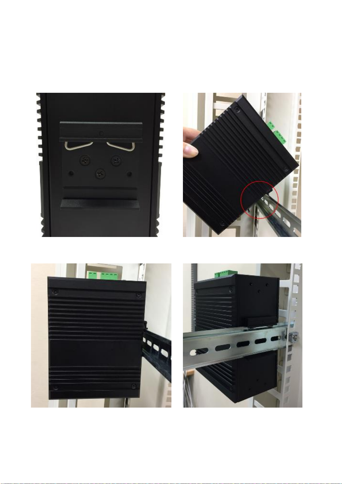
MOUNTING
Din-Rail Mounting
a. Screw the DIN-Rail bracket to the switch.
b. Insert the top of the DIN-Rail bracket to the
DIN-Rail track.
c. Pull down the DIN-Rail bracket to the DIN-Rail track and check if it is mounted tightly on the DIN-
Rail track.
Wall Mounting
a. Remove the DIN-Rail bracket.
b. Screw the wall mount kits to the switch.

9
INSTALLATION STEPS
1. Unpack
The switch is well packed and shipped to our customers. Unpack it from the box.
2. Check Content Items
Please make sure all the items listed in the "Package Check List" are in the box.
3. Mounting
The DIN-Rail is screwed on the switch by default. If the DIN-Rail is not screwed to the switch,
refer to the "DIN-Rail Mounting" section to install it manually.
The Wall mount brackets are optional items. If you need the wall mount brackets, contact us
for assistance. To install the switch on the wall, refer to the "Wall Mounting" section.
4. Power On
To power on the switch, users must prepare a power supply and wire the power input. Refer
to the "Wiring Power Inputs" section.
The power LEDs are described in the "LED Instruction" section.
5. Connect
To connect to the switch, users need a RJ45 cable. Insert the RJ45 cable into one of the switch
ports and insert the other end to the host such as PC.
The link LEDs are described in the "LED Instruction" section.
6. Check LEDs
We recommend the users to check the status of LEDs in the "LED Instruction" section. If all the
LEDs are in the normal state, the installation is completed.

10
Specification
Technology
Standards
IEEE 802.3 10BaseT
IEEE 802.3u 100BaseTX
IEEE 802.3ab 1000BaseT
IEEE 802.3z 1000BaseX
IEEE 802.3x Flow Control
IEEE 802.3af Power over Ethernet
IEEE 802.3at PoE+
IEEE 802.3ad/802.1AX LACP
IEEE 802.1D Spanning Tree Protocol
IEEE 802.1w Rapid STP
IEEE 802.1s Multiple STP
ITU-T G.8032 / Y.1344 ERPS
IEEE 802.1Q VLAN Tagging
IEEE 802.1ad Stacked VLANs
IEEE 802.1p Class of Service
IEEE 802.1X Network Authentication
IEEE 802.1AB LLDP
IEEE 1588 PTP
Processing Type
Store and Forward
Transfer Rate
14,880pps for Ethernet port
148,800pps for fast Ethernet port
1,488,000pps for gigabit Ethernet port
Transmission Distance
Up to 100M (Fast Ethernet)
Transmission Speed
Up to 1000Mbps
Switch Properties
Switch Fabric
24Gbps
Priority Queues
8 Queues
Jumbo Frame
9216bytes
MAC Table Size
16K
Packet Buffer
12Mbits
VLAN Table Size
4094
IGMP Group
512

11
ACL Group
512
VLAN IP Entries
64
Routing Entries
(IPv4/IPv6)
512/256 host, 64/64 LPM
Interface
RJ45 Port
8x 10/100/1000T(x) with PoE+, auto negotiation speed duplex mode,
auto MDI/MDI-X
Fiber Port
4x 1000F(x) SFP Slot
PoE Pin Out
V+, V+, V-, V-, for pin 1, 2, 3, 6, Endspan, MDI Mode A
LED Indicators
Per unit: PWR1, PWR2, Fault, Ring Master, Ring State
Ports: Link/Active with highest speed(Green), low speed(Amber)
PoE: Output Power
Alarm Contact
1x relay output with current carrying capacity of 1A @ 24 VDC
Digital Inputs
1x isolated input from the electronics.
+13 to +30V for state "1"
-30 to +3V for state "0"
Max. input current: 8mA
Button
Multiple functions reset button
Serial Console
1x RS232 in RJ45 connector with console cable, 115.2Kbps, 8N1
Storage
1x USB 2.0 storage for firmware update, configuration backup, restore,
boot up and syslog
Power Requirements
Operation Voltage
48-57VDC, redundant dual inputs, >50VDC for PoE+ output
recommended
Connection
1x removable 4-contact terminal block
Power Consumption
0.35A@48VDC without PDs' consumption
PoE Power Budget
Max. 240 W for total PD consumption, Max. 30 W per PoE port
Protection
Overload Current Protected, Reverse Polarity Protected
Mechanical Construction

12
Enclosure
Aluminum
Protection Class
IP30
Dimensions
72x145x118 mm (WxHxD)
Weight
0.90 kg
Mounting
DIN-Rail Mounting, Optional Wall Mounting Kits
Environmental Limits
Operating Temperature
Standard: -10°C ~ 60°C (14°F ~ 140°F)
Extended: -40°C ~ 75°C (-40°F ~ 167°F)
Storage Temperature
-40°C ~ 85°C (-40°F ~ 185°F)
Ambient Relative
Humidity
5 to 95%, (Non-Condensing)
Regulatory Approvals
EMI
CE EN 55032 Class A
EMS
IEC61000-4-2 (ESD)
IEC61000-4-3 (RS)
IEC61000-4-4 (EFT)
IEC61000-4-5 (Surge)
IEC61000-4-6 (CS)
IEC61000-4-8 (Magnetic Field)
Free Fall
IEC60068-2-32
Shock
IEC60068-2-27
Vibration
IEC60068-2-6
Green
RoHS Compliant
Certifications
UL 60950-1/62368 (Pending)
EN 50121-4
MTBF
>100,000 hours
Warranty
5 Years
This manual suits for next models
2
Table of contents
Other Subject Link Switch manuals


