ELC dmXLAN node8 User manual

dmXLAN node8
10-port DMX Ethernet node
Users Manual
Software version 1.0

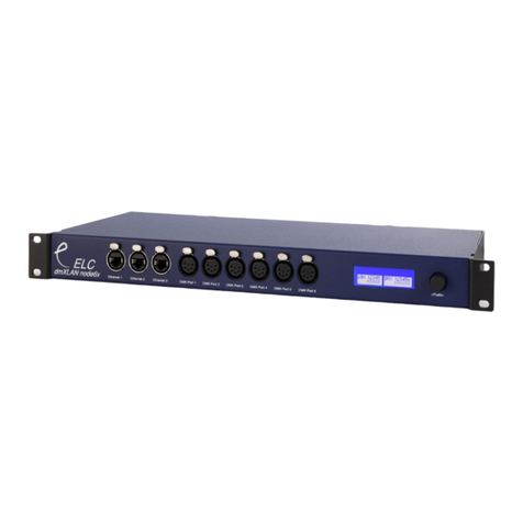
Front Panel
The front panel has a graphic LC-display, 3 keys and a jog-encoder with
push function and 4 LEDs.
Connections at the back
The dmXLAN node8 has many connectivity options. Viewed at the back from
left to right:
RS-232 (top SUB-D 9pin)
Pin Description
1 -
2 TX
3 RX
4 -
5 Ground
6-9 -
To connect the RS-232 port to a PC you’ll need a 1 to 1 male/female sub-d
9pin cable. (NO null-modem / cross cable)
Contact Closure Inputs (bottom SUB-D 9pin)
Pin Description
1 Ground / Shield
2 Input 1
3 Input 2
4 Input 3
5 Input 4
6-9 Ground
This inputs have an internal pull-up resistor. A simple switch can be
connected between the input pin and a ground pin. The contact inputs can be
used to temporarily recall a patch setting.
MIDI Out / MIDI In
Midi connection uses standard MIDI pinout.

Network 10/100 MBit Ethernet (on Neutrik Ethercon)
The network connection uses a standard UTP network connection.
USB 2.0 Full-speed
The USB connection uses standard USB pinout.
DMX port 1 - 8
Pin Description
1 Ground/Screen
2 Data -
3 Data +
4 -
5 -
The DMX ports 1 to 8 are bidirectional(via programmable setup), have an
internal terminator resistor and are RDM prepared.
DMX port 9 and 10
Pin Description
1 Ground/Screen
2 Data -
3 Data +
4 -
5 -
DMX ports 9 and 10 are fixed DMX inputs and have a fixed internal
terminator.
There are 2 versions of node8 available, the normal and the Full Isolated
(FI). The full isolated version has an optical/galvanic isolation barrier (up to
1500V).
This product may only be used for controlling
dimmers and moving lights. Using the product
out of these specifications will remove all
responsibility from the supplier

Operation
The dmXLAN node8 can be programmed in 2 ways.
Either through the front panel control or the dmXLAN control software.
The dmXLAN control software has to be software version 3.0 or up.
The software can be downloaded from www.elclighting.com
Control through front panel.
Main Display
A Select config menu, to recall 1 of 4 previously saved
configurations (patches)
B no function
(Setup) Enter setup menu
Encoder +/- Select information displays
Information displays
DMX port status
x port does not receive data (or DMX when input)
v port receives data (or DMX when input)
ID setting
IP address
Version and serial number

Setup menu
Enter the setup menu from the main screen by pressing
By using the encoder select the item you would like to adjust.
Options:
•Edit DMX port 1 to 8 or DMX input 9 and 10
•Set the ID
•Rename the current configuration
•Change network settings (ip address and netmask)
Edit the item by pressing A or the encoder.
All settings will be stored AFTER exiting the setup menu via the key, a
message will appear.
Edit DMX ports 1 to 8 or DMX input 9 and 10
Use the encoder to change the current selected option and press the
encoder to select the next option.
Press A to store the configuration
Press B to set the DMX port to it’s default value
Press to cancel any changes
DMX port as output
When a port is set up as a DMX output, then you can select the working
mode of that port. Modes are:
•disabled the DMX output is disabled
•outzero the DMX sends out a DMX test signal with all channels at
0%
•single the output sends out the DMX values of the selected
(primary) ArtNet universe. The DMX output is enabled the first time it
detects the DMX universe on the network (or internal DMX inputs). If
the universe on the network fails, the DMX output will go into DMX
hold.

•dual HTP like single, but merge two DMX universes (primary and
secondary) in highest take precedence.
•dual LTP like dual LTP, like dual HTP but in latest takes
precedence (on a channel by channel basis)
DMX port as input
When a port is set up as a DMX input, it can be operation in the following
modes.
•disabled the DMX input does nothing
•normal any valid DMX is sent onto the network (and internal use)
using the selected universe (ArtNet)
•backup the DMX input will not send data if the selected universe
is present on the network. If the selected universe is not present on
the network for several seconds and the input has valid DMX, then it
will send DMX data. If another sender starts sending the same
universe, the input will go back input backup mode.
Please note. DMX input 9 and 10 are always fixed to work as input.
Set ID
Used the encoder to change the current selected digit, and press the
encoder to select the next digit. The digits are in hexadecimal (16
possibilities 0-9, A-F). This means you can have upto 4095 different ID’s in
the system (ID 000 means that the ID is not used ---).
Press A to store
Press B to disable (---)
Press to cancel the operation

Rename current configuration
The name of the current configuration is presented in the Main display and in
the dmXLAN software. The name is also used to indicate the configuration
setting when it is stored in one of the 4 built in configurations.
Use the encoder to change the current character, and press the encoder to
select the next.
Press A to store the name
Press B to select the next character
Press to cancel the operation
Network settings
Use the encoder to change the current parameter, and press to select the
next.
Press A to store the configuration
Press B to select the factory default IP address and netmask
Press to cancel the operation
Configuration Menu
From the main display press A (config).
Now you can either recall a previous setup or store the current one in one of
the 4 options.
Use the encoder to select a setup
Press A to load the selected configuration
Press B to store the current configuration
Press to cancel the operation
The 4 contact closures on the back can be used to temporarily recall any of
the 4 setups. The configuration is loaded closing the contact and the normal

configuration is loaded when the contact is opened. Contact closure 4 has
the highest priority.
General Information
CE – Product
The dmXLAN node8 permits to the CE requirements set up by the European
Community. This can be recognized by this label on the outside of the
product.
Technical Specifications:
Power: 85-264 VAC 47-440 Hz 10VA max
Dimensions 19” 1HE rack unit 483 x 44 x 150 mm
Weight 2kg

Designed and manufactured in the Netherlands by:
ELC lighting
Support contact: support@elclighting.com
Distributed by:
Worldwide distribution:
ANIMA lighting Ltd
Route du Stand 20
CH-1897 Le Bouveret
Switzerland
T +41 79 210 4613
F+4186 079 210 4613
Email: sales@elclighting.com
URL: www.elclighting.com
Table of contents
Other ELC Switch manuals
Popular Switch manuals by other brands
TRENDnet
TRENDnet TPE-80WS - Web Smart PoE Switch Specifications

Huawei
Huawei S2750 Hardware description
Dell
Dell PowerConnect W-IAP175P manual
Z-Band
Z-Band ZBT0100052 User guide and installation manual
Gefen
Gefen EXT-DVIKVM-241DL user manual
Cisco
Cisco 6503 - Catalyst Firewall Security Sys Product bulletin
