Subject Link RPT-1008G-X2 Instructions for use

Industrial Unmanaged Ethernet Switch Hardware User Manual
RPT-1008G(-T)-X2
Version 1.0.0
Subject Link Inc
9F-1, No. 77, Sec 4., Nangjing E. Rd, Taipei City, 10580, Taiwan, R.O.C.
Tel: +886 935 672 398
Web: www.sbjlink.com

Contents
Overview ...........................................................................................................................................................1
Package Check List...................................................................................................................................1
Hardware Description..................................................................................................................................2
Front Panel Instruction ..........................................................................................................................2
Dimensions..................................................................................................................................................2
Top View ......................................................................................................................................................3
LED Instruction ..........................................................................................................................................3
Earth Grounding........................................................................................................................................3
Hardware Installation...................................................................................................................................4
Wiring Power Inputs ...............................................................................................................................4
Wiring Fault Alarm...................................................................................................................................4
Double-Secure Power Input Fault Alarm........................................................................................4
Mounting .....................................................................................................................................................5
Installation Steps......................................................................................................................................6
Specification.....................................................................................................................................................7

1
Overview
This user manual is for "RPT-1008G(-T)-X2" with extended operating temperature (-40°C ~ 75°C
(-40°F ~ 167°F)). This is an industrial unmanaged gigabit Ethernet switch with the following hardware
features:
Interface
▪MDI/MDI-X function supported on all copper ports
▪Embedded 8x Gigabit Ethernet ports
▪Store-and-forward switching architecture
Switch Properties
▪Up to 4K MAC Address Table supported
▪Up to 1.5Mbits Packet Buffer supported
Power Input
▪Redundant 12-48VDC power
Temperature
▪Extended operating temperature: -40°C ~ 75°C (-40°F ~ 167°F)
▪Storage temperature: -40°C ~ 85°C
Mechanical Construction
▪Class IP30 protection
▪DIN-Rail Mounting
PACKAGE CHECK LIST
The "RPT-1008G(-T)-X2" is shipped with the following items. Ensure that all the items are in the
box. If any item is missing or damaged, contact us for assistance.
▪RPT-1008G(-T)-X2 switch x 1
▪Protective caps for 8x copper ports
▪Wall mount brackets and screws (Optional)

2
Hardware Description
FRONT PANEL INSTRUCTION
The following picture is the front panel for "RPT-1008G(-T)-X2".
DIMENSIONS
WxHxD: 29x140x98 mm

3
TOP VIEW
This is the top view of the RPT-1008G(-T)
containing the ground, power inputs, fault
alarm relay.
LED INSTRUCTION
System LEDs
LED
Color
Status
Description
PWR1
Green
On
Power is supplied on the power input 1.
Off
Power is not supplied on the power input 1.
PWR2
Green
On
Power is supplied on the power input 2.
Off
Power is not supplied on the power input 2.
Fault
Red
On
The power input 1 or power input 2 is failed.
Off
The power input 1 and power input 2 are in normal operation.
Interface Status LEDs
LED
Color
Status
Description
LAN Port
P1 to P8
(1000M)
Green
On
The 1000Mbps link of the port is active.
Flashing
Data is transmitted on the port at 1000Mbps.
Off
The 1000Mbps link of the port is inactive.
LAN Port
P1 to P8
(10/100M)
Amber
On
The 10/100Mbps link of the port is active.
Flashing
Data is transmitted on the port at 10/100Mbps.
Off
The 10/100Mbps link of the port is inactive.
EARTH GROUNDING
The earth grounding and cautious wire routing are helpful to suppress the effects of noise from
electromagnetic interference (EMI). The switch has to be installed on a well-grounded surface, for
instance, a metal panel.
The location of earth ground screw is usually near the location of power
inputs, for example:
▪Top side for most of din-rail models
▪Rear side for most of rack-mount models
▪Front side for most of M12 models
Note: Connect the ground from the ground screw to the surface of ground before wiring the
power inputs.
4
Hardware Installation
WIRING POWER INPUTS
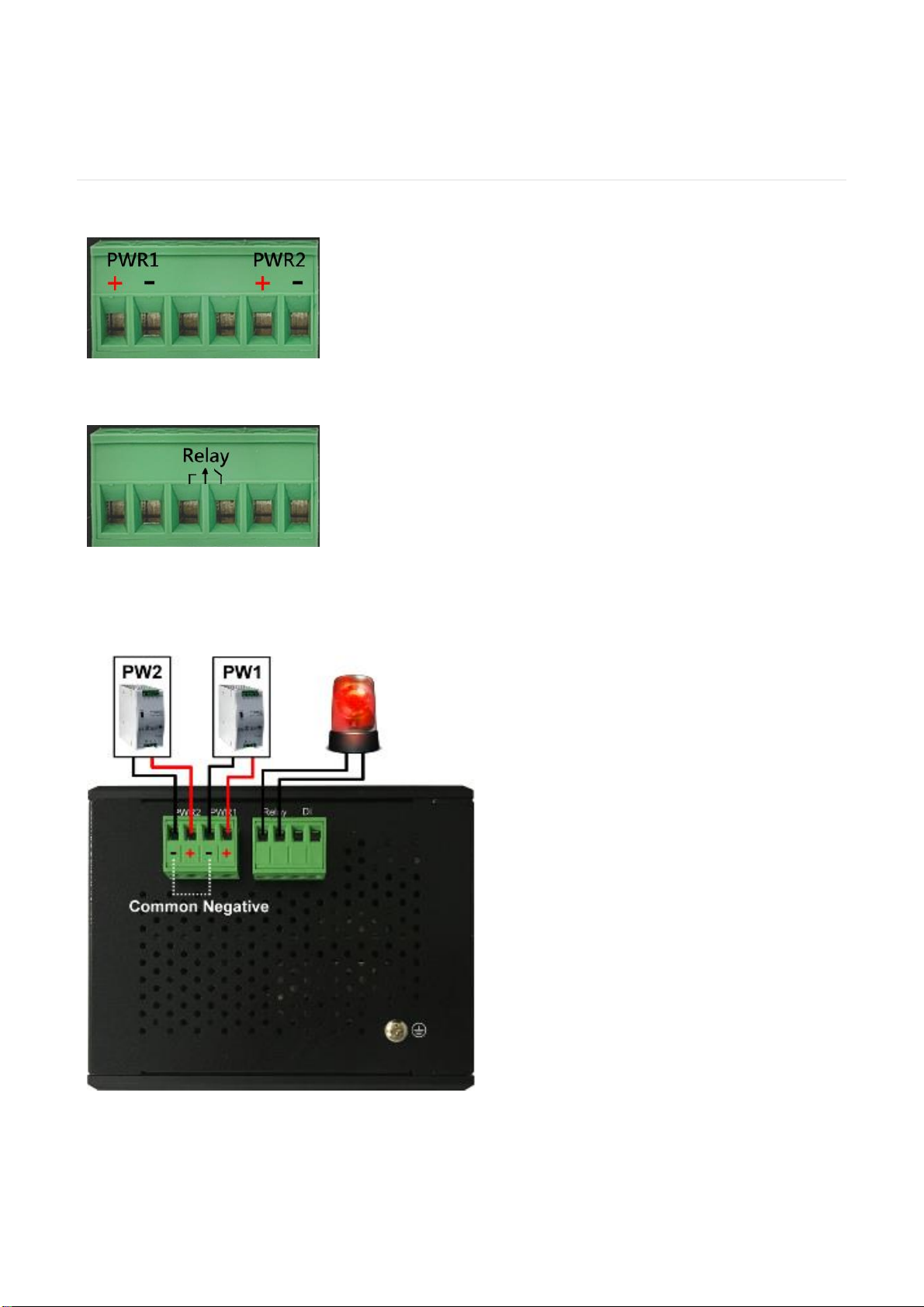
1. Insert the positive and negative wires into the PWR1 (+,-) and
PWR2 (+,-) on the 6-contact terminal block connector.
2. Tighten the screws to prevent the wires from loosening.
WIRING FAULT ALARM
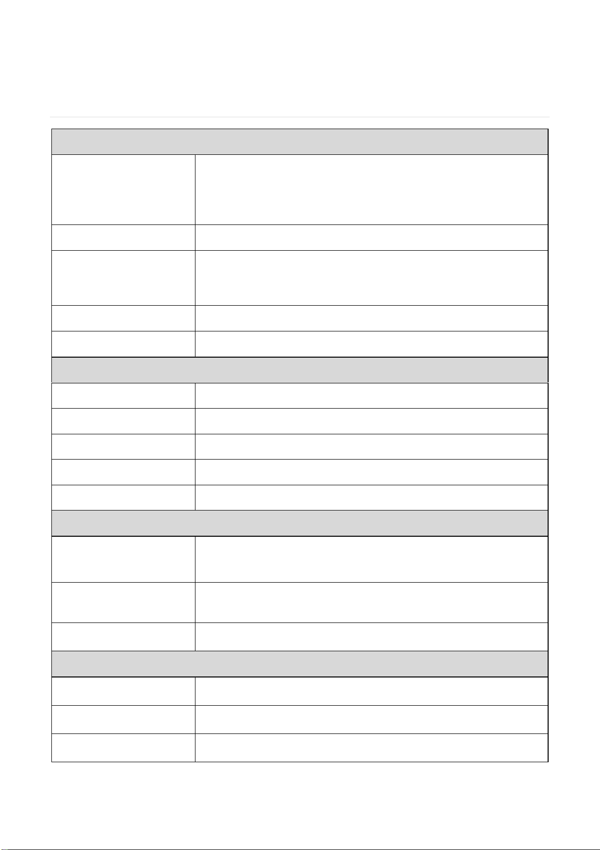
1. Insert the wires into the left two contacts of the 6-contact
terminal block (Fault Alarm Relay).
2. Tighten the screws to prevent the wires from loosening.
3. The relay will detect the power and link failure.
4. Users can connect the relay to an alarm and buzzer so that
when the relay forms an open circuit, the users will be notified.
DOUBLE-SECURE POWER INPUT FAULT ALARM
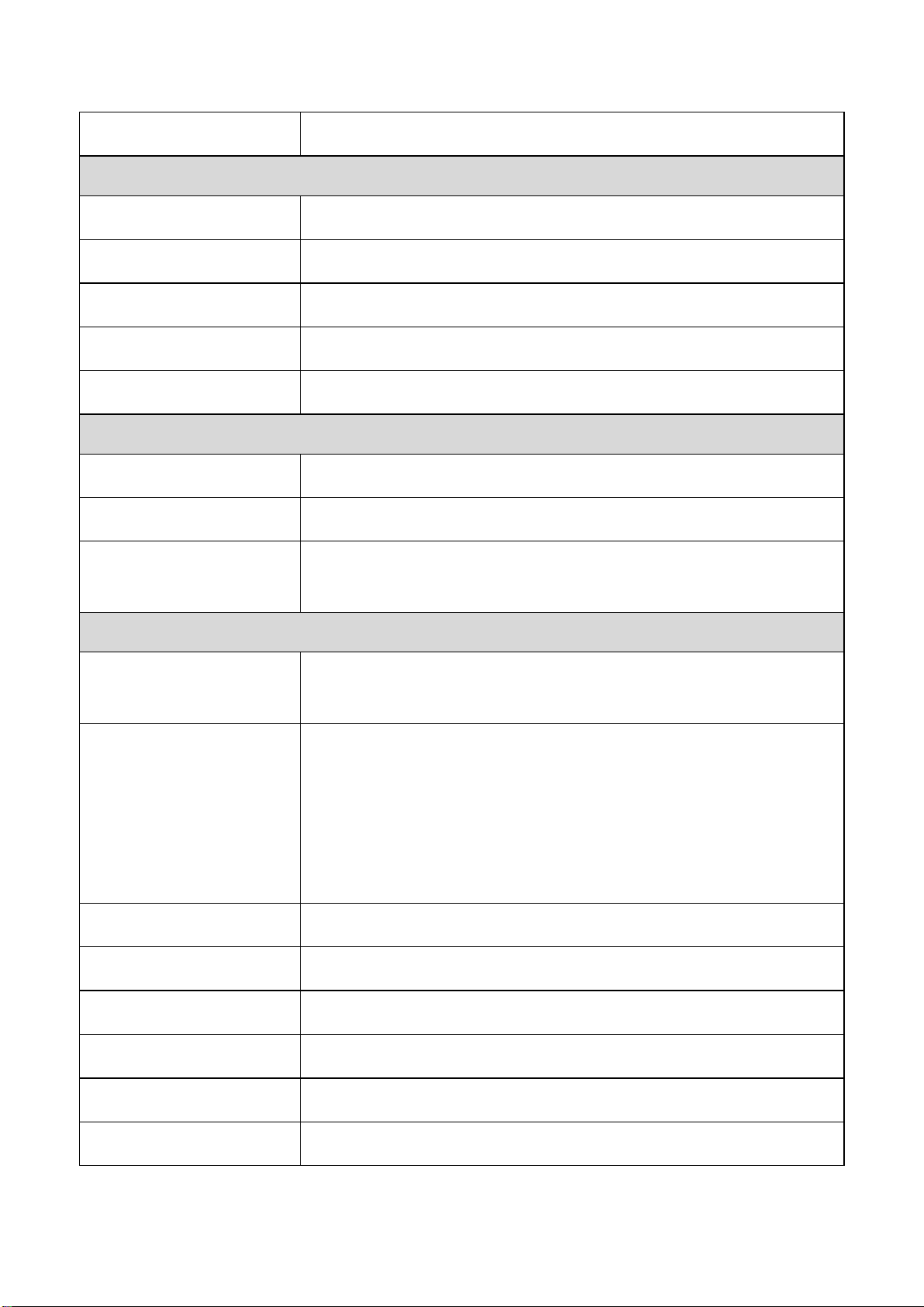
The power inputs are designed as a "common
negative", which implies that the negative
input is connected, but "double-secure" is
supported to prevent the unnotified failure of
power from one of the negative inputs. Should
one of the negative power inputs fail, the
system will detect the failure. NOTE: the
system will trigger an event occurrence only if
the user has set the fault alarm or event log
for power.

5
MOUNTING
Din-Rail Mounting
a. Screw the DIN-Rail bracket to the switch.
b. Insert the top of the DIN-Rail bracket to the DIN-
Rail track.
c. Pull down the DIN-Rail bracket to the DIN-Rail track and check if it is mounted tightly on the DIN-
Rail track.
Wall Mounting
a. Remove the DIN-Rail bracket.
b. Screw the wall mount kits to the switch.

6
INSTALLATION STEPS
1. Unpack
The switch is well packed and shipped to our customers. Unpack it from the box.
2. Check Content Items
Please make sure all the items listed in the "Package Check List" are in the box.
3. Mounting
The DIN-Rail is screwed on the switch by default. If the DIN-Rail is not screwed to the switch,
refer to the "DIN-Rail Mounting" section to install it manually.
The Wall mount brackets are optional items. If you need the wall mount brackets, contact us
for assistance. To install the switch on the wall, refer to the "Wall Mounting" section.
4. Power On
To power on the switch, users must prepare a power supply and wire the power input. Refer
to the "Wiring Power Inputs" section.
The power LEDs are described in the "LED Instruction" section.
5. Connect
To connect to the switch, users need a RJ45 cable. Insert the RJ45 cable into one of the switch
ports and insert the other end to the host such as PC.
The link LEDs are described in the "LED Instruction" section.
6. Check LEDs
We recommend the users to check the status of LEDs in the "LED Instruction" section. If all the
LEDs are in the normal state, the installation is completed.
7
Specification
Technology
Standards
IEEE 802.3 10BaseT
IEEE 802.3u 100BaseTX
IEEE 802.3ab 1000BaseT
IEEE 802.3x Flow Control
Processing Type
Store and Forward
Transfer Rate
14,880pps for Ethernet port
148,800pps for fast Ethernet port
1,488,000pps for gigabit Ethernet port
Transmission Distance
Up to 100M (Fast Ethernet)
Transmission Speed
Up to 1000Mbps
Switch Properties
Switch Fabric
16Gbps
Priority Queues
-
Jumbo Frame
-
MAC Table Size
4K
Packet Buffer
1.5Mbits
Interface
RJ45 Port
8x 10/100/1000T(x), auto negotiation speed duplex mode, auto
MDI/MDI-X
LED Indicators
Per unit: PWR1, PWR2, Fault
Ports: Link/Active(Green)
Alarm Contact
1x relay output with current carrying capacity of 1A @ 24 VDC
Power Requirements
Operation Voltage
12-48VDC, redundant dual inputs
Connection
1x removable 6-contact terminal block
Power Consumption
0.18A@24VDC
8
Protection
Overload Current Protected, Reverse Polarity Protected
Mechanical Construction
Enclosure
Steel metal
Protection Class
IP30
Dimensions
29x140x98 mm (WxHxD)
Weight
0.75 kg
Mounting
DIN-Rail Mounting
Environmental Limits
Operating Temperature
Extended: -40°C ~ 75°C (-40°F ~ 167°F)
Storage Temperature
-40°C ~ 85°C
Ambient Relative
Humidity
5 to 95%, (Non-Condensing)
Regulatory Approvals
EMI
FCC Part 15 Subpart B Class A
CE EN 55032 Class A
EMS
IEC61000-4-2 (ESD)
IEC61000-4-3 (RS)
IEC61000-4-4 (EFT)
IEC61000-4-5 (Surge)
IEC61000-4-6 (CS)
IEC61000-4-8 (Magnetic Field)
Free Fall
IEC60068-2-32
Shock
IEC60068-2-27
Vibration
IEC60068-2-6
Green
RoHS Compliant
MTBF
>100,000 hours
Warranty
5 Years
This manual suits for next models
1
Table of contents
Other Subject Link Switch manuals


