Suisei EFP-RC2 Instructions and recipes

(1/24)EFP-RC2 Supplementary manual
(For RX66T)
EFP-RC2 Supplementary manual
(For RX66T)
Suisei Electronics System CO.LTD.,
1st Edition issue Apr. 2020
1. General Description
This supplement contains information required for reading, writing and erasing data to/from Renesas Electronics RX66T
series MCU with built-in flash memory.
2. Operating Environment and List of supporting MCU
2.1 Operating Environment
Use the MCU mentions in this supplement in an environment as follows.
Table2.1 Operating environment
MCU series name
EFP-RC2 Version
RX66T series
Ver.2.00.04 or later
If your S/W version of EFP-RC2 is old one, download the latest version data from the website below.
< EFP-RC2 latest S/W free download site >
http://www.suisei.co.jp/download_e/productdata_efprc2_e.html
2.2 List of supporting MCU
Show correspondence MCU table in Table2.2 The program to the RX family in EFP-RC2 needs the setting of the MCU
type.
Please set MCU type by MCU set command of the script command.
Please refer to MCU set command of the EFP-RC2 instruction manual for the details of the MCU set command.
Table2.2 List of supporting MCU
Set value of the MCU type
Correspondence MCU series name
38 : RX ( Little endian )
39 : RX ( Big endian )
RX66T

(2/24)EFP-RC2 Supplementary manual
(For RX66T)
3Connect EFP-RC2 with target system
Please connect EFP-RC2 and the connection with the user target system using EF1TGCB-X( tip wire press cable ) or
EF1TGCB-B(4 wire type target connection cable) to show it in Fig3.1.
Fig3.1 Connection with target system

(3/24)EFP-RC2 Supplementary manual
(For RX66T)
4Pin Connection
Table4.1 lists the connection of target connection cable pin of the RX66T series.
Table4.1 Connection of the Target Connection Cable Pin (RX66T series)
Pin No.
(EFP-RC2 side)
Target End Wire
Color
Signal
4-wire Cable
Pin No.
MCU Connection Pin For
Serial Input/Output
Input/Output
(writer side)
1
Orange/red dotted1
GND
1
Connects to VSS pin *3
-
3
Gray/red dotted1
T_VPP
4
Unconnected
Open
4
Gray/black dotted1
T_VDD
5
Connects to VCC pin *1
Input
8
White/black dotted1
T_PGM/OE/MD
8
Unconnected *4
Output
9
Yellow/red dotted1
T_SCLK
6
Unconnected
Output
10
Yellow/black
dotted1
T_TXD
7
Connects to RXD pin*5
Output
11
Pink/red dotted1
T_RXD
2
Connects to TXD pin*5
Input
12
Pink/black dotted1
T_BUSY
3
Unconnected *4
Input/Output
14
Orange/black
dotted2
T_RESET
9
Connects to RESET pin *2
Output
16
Gray/black dotted2
GND
10
Connects to VSS pin *3
-
< Supplement of Pin Treatment >
*1 : Supply VCC from user side to match source voltage of output buffer used on EFP-RC2 side with user side source voltage
(VCC).
*2 : Reset cancel is not carried out during using a writer. To execute user program, you should therefore unplug the target connection
cable to the writer. As for RESET output at writer side, see Note 2 in the page 4.
*3 : The signal GND has 2 pins(No.1,16)of EFP-RC2 side connector. When connecting to the target board, you can connect with
using only one pin, but connecting more than 2pins is recommended.
<Supplement for others >
*4: When the Handling of mode pins is not possible with a user target board, please be connected to the mode terminal of MCU.
T_PGM/OE/MD = “H” Output, T_BUSY = “L” Output
*5: Connect to the pins (boot mode SCI interface pins) described in the table of "I / O pins used in boot mode" in the MCU hardware
manual.
(4/24)EFP-RC2 Supplementary manual
(For RX66T)
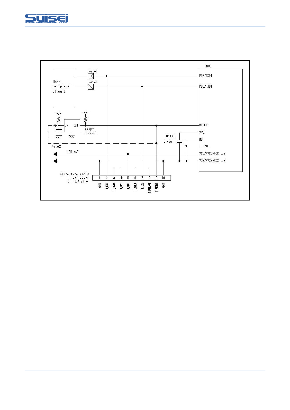
5User target recommendation circuit
5.1 User target recommendation circuit
A recommended sample of user target MCU peripheral circuit for RX66T is shown in Fig5.1.
Fig5.1 User Target Peripheral Circuit Example(For RX66T)
1: If the user peripheral circuit is an output circuit, you should disconnect by jumper to avoid output collision
when executing serial I/O mode. (see Fig5.)
2: EFP-RC2 side reset output is an open collector therefore connect to the RESET pin with 1kΩ pull -up resistor
for open collector output. If the reset circuit is CMOS output, disconnect by jumper as described in Notes
1, or connect the EFP-RC2 side T_RESET signal to reset circuit input.
By TXD from a writer, RXD and in combination in RESET signal output timing, a serial input and output
mode entry is performed. Please become less than 500ns in the L → H output timing of TXD, RXD and
the RESET signal.
3: Please connect the VCL terminal to GND through capacitor (0.47uF).

(5/24)EFP-RC2 Supplementary manual
(For RX66T)
5.2 Collision prevention circuit example
An example of collision prevention circuit when user peripheral circuit outputs is shown Fig5..
※プログラム時ジャンパを外す。
*Disconnect jumper when programming.
Fig5.2 Collision Prevention Circuit Using Jumper
5.3 Handling of mode Pins
For the RX66T series, implement the terminal treatment of the mode terminal as shown in Table 5.1.
When the handling of the Mode pins is not possible on a user target board, connect the T_BUSY pin of EFP-RC2 to the
mode pin of MCU.
Table5.1 Handling of mode pins
MCU series name
Mode pin
name
Pin handling
pin handling in EFP-RC2
Signal name(4-wire Cable Pin No.)
RX66T
MD
L
T_BUSY (3)
P00
L
T_BUSY (3)
*: L connects with GND

(6/24)EFP-RC2 Supplementary manual
(For RX66T)
6List of available commands
Show a list of available commands in table6.1 in RX66T series.
Table6.1 List of available commands(RX66T series)
Command name
Description
command
Summary
Page no.
MCU-set
T
Target MCU is set.
7
VDD Supply
X
It supplies VDD in target MCU
7
Baudrate set
S
Change transmission rate.
8
Mode entry
M
Carry out a mode entry to communication with RX family.
10
ID setting/verification
I
Setting and verification of ID code protection function
11
Erase
E
Flash ROM with built-in MCU, all areas are erased.
12
Blank check
B
Check that the MCU built-in ROM has been erased
13
Program
P
The content of the Hxw file is written with built-in MCU ROM.
14
Verify
V
The data with built-in MCU ROM is collated with the content of the
Hxw file.
15
Read
R
Reads data from MCU internal ROM to EFP-RC2
15
Check sum
H
confirm a checksum value of the MCU built-in ROM.
16
Lock bit
K
The lock bit with built-in MCU ROM is set in the lock.
16
Option
O
Option protect setting
17
Wait
W
The script operation is stopped temporarily.
20

(7/24)EFP-RC2 Supplementary manual
(For RX66T)
7Command descriptions for RX66T series
Explain the command for dedicated of the RX66T series.
7.1 MCU set command
Command by which target MCU is specified
Format : t=x
t=xx ; x disregard the effective following from the head to 2 digits.
XX: 38 and 39 are effective. The first two digits are valid and the rest are ignored.
38: RX (little endian)
39: RX (big endian)
Description example :
T = 38; Specify RX little endian as the target MCU
Detail:
Target MCU according to compatible products is designated.
Please describe this command on the top of PBT file.
7.2 VDD supply command
Format : x=1
Description example :
x=1 ; Vdd is supplied to MCU
Detail:
1. VDD(+5V) is supplied to target MCU and access including data read, verification, writing in, etc. is enabled.
2. In case power is not supplied to target MCU and VDD supply command is not included in script, an error occurs.
Note:
: Only + 5V can output VDD from EFP-RC2.
If the power supply voltage exceeds the absolute maximum rating of the MCU, the MCU may be damaged. Please
use it after confirming enough.
: Current capacity that can be provided is up to about 300mA. Nonetheless in case incoming current of substrate is too
much, an error occurs, and in the worst case EFP-RC2 itself is reset. In case this command is used, please do so,
taking account of consumption current of target substrate.
: Please describe this command after MCU set command.

(8/24)EFP-RC2 Supplementary manual
(For RX66T)
7.3 Baudrate set command
The command which changes the baud rate to access.
Format : N=xxx
xxx : (Valid until 1-256)
Description example :
N=4 ;500kBps is used for access with MCU.
N ;Error ( no argument )
Detail:
RX family is in communication at 9600bps when accessing data read, verify, and writing.
You can shorten the processing time to change the baud rate to access. The value to be set, please refer to Table7.1-
Table7.2.
Please description after the MCU set command (T command ) This command is.
Note:
After setting, changing does MCU setting (T command) or works at the baud rate that set until cut the power supply of
the main body of EFP-RC2.
Table7.1 Setting baud rate(1)
Setting
Baud rate
Setting
Baud rate
Setting
Baud rate
Setting
Baud rate
N=1
2000000
N=25
80000
N=49
40816
N=73
27397
N=2
1000000
N=26
76923
N=50
40000
N=74
27027
N=3
666666
N=27
74074
N=51
39215
N=75
26666
N=4
500000
N=28
71428
N=52
38461
N=76
26315
N=5
400000
N=29
68965
N=53
37735
N=77
25974
N=6
333333
N=30
66666
N=54
37037
N=78
25641
N=7
285714
N=31
64516
N=55
36363
N=79
25316
N=8
250000
N=32
62500
N=56
35714
N=80
25000
N=9
222222
N=33
60606
N=57
35087
N=81
24691
N=10
200000
N=34
58823
N=58
34482
N=82
24390
N=11
181818
N=35
57142
N=59
33898
N=83
24096
N=12
166666
N=36
55555
N=60
33333
N=84
23809
N=13
153846
N=37
54054
N=61
32786
N=85
23529
N=14
142857
N=38
52631
N=62
32258
N=86
23255
N=15
133333
N=39
51282
N=63
31746
N=87
22988
N=16
125000
N=40
50000
N=64
31250
N=88
22727
N=17
117647
N=41
48780
N=65
30769
N=89
22471
N=18
111111
N=42
47619
N=66
30303
N=90
22222
N=19
105263
N=43
46511
N=67
29850
N=91
21978
N=20
100000
N=44
45454
N=68
29411
N=92
21739
N=21
95238
N=45
44444
N=69
28985
N=93
21505
N=22
90909
N=46
43478
N=70
28571
N=94
21276
N=23
86956
N=47
42553
N=71
28169
N=95
21052
N=24
83333
N=48
41666
N=72
27777
N=96
20833
unit[bps]

(9/24)EFP-RC2 Supplementary manual
(For RX66T)
Table7.2 Setting baud rate(2)
Setting
Baud rate
Setting
Baud rate
Setting
Baud rate
Setting
Baud rate
N=97
20618
N=137
14598
N=177
11299
N=217
9216
N=98
20408
N=138
14492
N=178
11235
N=218
9174
N=99
20202
N=139
14388
N=179
11173
N=219
9132
N=100
20000
N=140
14285
N=180
11111
N=220
9090
N=101
19801
N=141
14184
N=181
11049
N=221
9049
N=102
19607
N=142
14084
N=182
10989
N=222
9009
N=103
19417
N=143
13986
N=183
10928
N=223
8968
N=104
19230
N=144
13888
N=184
10869
N=224
8928
N=105
19047
N=145
13793
N=185
10810
N=225
8888
N=106
18867
N=146
13698
N=186
10752
N=226
8849
N=107
18691
N=147
13605
N=187
10695
N=227
8810
N=108
18518
N=148
13513
N=188
10638
N=228
8771
N=109
18348
N=149
13422
N=189
10582
N=229
8733
N=110
18181
N=150
13333
N=190
10526
N=230
8695
N=111
18018
N=151
13245
N=191
10471
N=231
8658
N=112
17857
N=152
13157
N=192
10416
N=232
8620
N=113
17699
N=153
13071
N=193
10362
N=233
8583
N=114
17543
N=154
12987
N=194
10309
N=234
8547
N=115
17391
N=155
12903
N=195
10256
N=235
8510
N=116
17241
N=156
12820
N=196
10204
N=236
8474
N=117
17094
N=157
12738
N=197
10152
N=237
8438
N=118
16949
N=158
12658
N=198
10101
N=238
8403
N=119
16806
N=159
12578
N=199
10050
N=239
8368
N=120
16666
N=160
12500
N=200
10000
N=240
8333
N=121
16528
N=161
12422
N=201
9950
N=241
8298
N=122
16393
N=162
12345
N=202
9900
N=242
8264
N=123
16260
N=163
12269
N=203
9852
N=243
8230
N=124
16129
N=164
12195
N=204
9803
N=244
8196
N=125
16000
N=165
12121
N=205
9756
N=245
8163
N=126
15873
N=166
12048
N=206
9708
N=246
8130
N=127
15748
N=167
11976
N=207
9661
N=247
8097
N=128
15625
N=168
11904
N=208
9615
N=248
8064
N=129
15503
N=169
11834
N=209
9569
N=249
8032
N=130
15384
N=170
11764
N=210
9523
N=250
8000
N=131
15267
N=171
11695
N=211
9478
N=251
7968
N=132
15151
N=172
11627
N=212
9433
N=252
7936
N=133
15037
N=173
11560
N=213
9389
N=253
7905
N=134
14925
N=174
11494
N=214
9345
N=254
7874
N=135
14814
N=175
11428
N=215
9302
N=255
7843
N=136
14705
N=176
11363
N=216
9259
N=256
7812
unit[bps]

(10/24)EFP-RC2 Supplementary manual
(For RX66T)
7.4 Mode entry command
Execute a mode entry command and make each command feasible.
Record detailed MCU information in a log file.
Format : M,OCO[,MCU detailed information]
MCU detailed information : Blank: No log output, 1: Log output
Description example:
M,OCO : No log output of MCU detailed information
M,OCO,1 : MCU detailed information log is output
Detail:
Firstly it is necessary to execute a mode entry command to execute a command in RX66T series. Please fill in this
command after baud rate setting command. (S command)
Table7.3 shows the MCU information that can be referenced by this command.
No.1-2 is always displayed when this command is executed.
No.3-10 is displayed only when the setting is valid.
No.11 is displayed when MCU detailed information is set to “1”.
Table7.3 MCU information
No.
Display location
What to display
1
DEVICE NAME
MCU series name
2
ROM INFORMATION
ROM area, ROM size
3
OFS DATA Enabled!!
OFS0 / OFS1 register setting
4
READ Protected.
Read protection enabled
5
PROGRAM Protected.
Program protect is enabled
6
BLOCK ERASE Protected.
Block erase protect is enabled
7
TM SETTING Enabled.
Arbitrary code when setting TM area
8
SERIAL CONNECT Protected!!
Serial programmer connection prohibition
function is enabled
9
SERIAL AUTETICATION ID Enabled.
Boot mode ID authentication is enabled
10
OCD ID Enabled.
OCD ID is valid
11
ERASE BLOCK
Configuration of erase block
Note:
If boot mode ID authentication is set, MCU detailed information is output after the ID collation command.

(11/24)EFP-RC2 Supplementary manual
(For RX66T)
7.5 ID setting / verification command
Setting and verification of ID code protection function
Format : I, [ID type], [ID code], [ID code format]
* ID type : 0:OCD (On-chip debugger) ID code
1: Boot mode ID authentication code
* ID code : User setting value of 16 bytes (If less than 16 bytes, add 0 at the end)
* ID code format : 0:input by ASCII codes, 1:input by HEX codes
Description example :
i,1,010203040050708090a0b0c0d0e0f00,1 ;Boot mode ID code, HEX input
i,0,SUISEI_DENSHI,0 ;OCD ID code, ASCII input
Detail :
(1) Setting of boot mode ID authentication code
Set the ID code required for EFP-RC2 connection to the MCU for which ID code is not set.
(2) Verification of boot mode ID authentication code
The MCU that has already set the ID code is compared with the ID authentication code.
(3) OCD ID code setting
Set the ID code required when connecting to an on-chip debugger (such as E1).
Either the OCD ID code or the boot mode ID authentication code can be set.
Write this command after the mode entry command (M command).
Note:
* It cannot be used if protection (read, program, block erase prohibited) has already been set.
If the boot ID authentication code is set, the protection setting cannot be used.
* To clear the set ID code, it is necessary to execute the configuration clear command. (refer P.18)
* When changing MCU with OCD ID code to boot mode ID authentication, execution of configuration clear command is
not required.
* Use the ID code setting according to your application.

(12/24)EFP-RC2 Supplementary manual
(For RX66T)
7.6 Erase command
Erasing MCU built-in ROM.
Format : E,,[lock bit form] ;all area erase
E,[Block End address],[Lock bit form] ;block erase
E,[Block Start address], [Block End address], [Lock bit form] ;Erase of continuous block
* Block Start address : Start address of the block to erase.
* Block End address : End address of the block to erase.
* Lock bit form : 0 : effective, 1 : invalidity
Description example:
E,,1 ;all area erase
E,FFFFFFFF,1 ;One block erase
E,FFF80000,FFFFFFFF,1 ;Erase Consecutive Blocks
Detail:
All erase erases the user area and data area. The user boot area is not erased.
In one block erase, only the specified block can be erased.
When erasing multiple consecutive blocks, it is possible to batch erase multiple blocks in the specified range by
specifying the start address and end address.
If the lock bit format is enabled, only unlocked blocks are erased. Locked blocks are not erased.
If lock bit format invalid is selected, it will be erased regardless of the lock / unlock status.
Note:
* A protection error will occur if block erasure prohibition of the protection function is enabled or in areas where TM
(trusted memory) is set.
* If all erase is executed while TM is set, all areas except the TM setting area will be erased. No error occurs.

(13/24)EFP-RC2 Supplementary manual
(For RX66T)
7.7 Blank check command
Format: B,[Start address],[End address]
* Start address : Start address of the area to be Blank check.
* End address : End address of the area to be Blank check.
Description example:
B,FFFFF000,FFFFFFFF
Detail:
Checks that the MCU built-in ROM within the specified range has been erased.
Note:
* In the RX66T series, execution units differ between the code flash area and data flash area. Specify the start address
and end address as shown in the table below.
Table7.4 Start / End Address
Memory area
Execution unit
[Byte]
Start address
End address
Code flash
256
xxxxxx00h
xxxxxxFFh
Data flash
16
xxxxxxx0h
xxxxxxxFh
* A blank error will occur if the area is set to TM (trusted memory).

(14/24)EFP-RC2 Supplementary manual
(For RX66T)
7.8 Program command
The content of the Hxw file is written with built-in MCU ROM.
Format: P,[Hxw file name],[start address],[end address],[lock bit form]
* Hxw file name : Please specify the name of the Hxw files that have been downloaded to EFP-RC2.
* start address : Start address of the area to be written
* end address : End address of the area to be written
* lock bit form : 0 : lock bit effective, 1 : Lock bit invalidity
Description example:
P,SAMPLE.Hxw,FFFFF000,FFFFFFFF,1
Detail:
Write Hxw data from the start address to the end address in the MCU built-in ROM.
If the lock bit is enabled, an error occurs if there is a locked area.
If the lock bit is invalid, writing can be performed even if there is a locked area if the data has been erased.
Note:
* The maximum size of the Hxw file that can be stored in the EFP-RC2 is 2 MB, so when writing data of 2 MB or more,
split the Hxw file and save it.
* An error will occur if an address outside the address range of the Hxw file is described in the start address and end
address.
* In the RX66T series, the write execution unit differs between the code flash area and data flash area. Specify the start /
end address according to the execution unit shown in Table7.4 of “7.7 Blank Check Command”
* When the end address of the MOT file is not xxxxxxFFh, in the case of the conversion from MOT in RC-Downloader
to Hxw file, please set "Setting type" in "Manual" in an item of "Hxw data domain setting". Please convert top address
into xxxxxx00h with an end address as xxxxxxFFh.
MOT file area that does not exist in the source file at this time, 0xFF is set as data.
* If the program prohibition of the protection function is enabled or if the area is set to TM (trusted memory), a
protection error will occur.
* When writing to the configuration area (120000h –1200FFh) of the option setting memory, use the O command (P.17)

(15/24)EFP-RC2 Supplementary manual
(For RX66T)
7.9 Verify command
Format :V,[Hxw file name],[start address],[end address]
* Hxw file name : Please specify the name of the Hxw files that have been downloaded to EFP-RC2.
* start address : Start address of the area to be verify check
* end address : End address of the area to be verify check
Description example:
V,LC-PBT.Hxw,FFFFF000,FFFFFFFF
Detail:
The contents of the MCU internal ROM in the specified range are compared with the contents of the Hxw file.
Note:
* Specify the start / end address according to the execution unit shown in Table7.4 of ”7.7 Blank Check Command”.
* If read protection of the protection function is enabled, a protection error will occur.
* Since "0" is read from the area set as TM (trusted memory), a verification error will occur if the collation data is not
"0".
7.10 Read command
Format: R,[Hxw file name],[start address],[end address]
* Hxw file name:Specify here the hxw file name, to be read in EFP-RC2.
* start address:Start address of the area to be read.
* end address:End address of the area to be read.
Description example:
R,read.Hxw,FFFF0000,FFFFFFFF
Detail:
Reads the data in the specified range of the MCU built-in ROM to the EFP-RC2 CF card.
If a file with the same name exists, it will be overwritten.
Note:
* Specify the start / end address according to the execution unit shown in Table7.4 of ”7.7 Blank Check Command”
* If read protection of the protection function is enabled, a protection error will occur.
* "0" is read from the area where TM (trusted memory) is set.
* If an erased data flash area is read, the read data will be undefined.

(16/24)EFP-RC2 Supplementary manual
(For RX66T)
7.11 Check sum command
The command verify the check sum of MCU built-in ROM data.
Format: H,[Type of Flash],[ROM capacity],[check sum value]
* type of Flash : 1 : user area, 2 : data area, 3 : user boot area
* ROM capacity : Input by KB unit ( 64KB -> 64 )
* check sum value : 4Byte (The long word data which added by a 1 byte unit (hexadecimal) )
Description example:
H,1,256,1D4B59E6
Detail:
Check that the checksum value specified in the Pbt file matches the checksum value of the data in the MCU internal
ROM.
Note:
* The checksum value is longword data obtained by adding all data in the ROM area in byte units.
* If there is an unwritten area in the data area, the data will be undefined.
7.12 Lock bit command
The lock bit at every the block with built-in MCU ROM can be set in the lock, and the thing to prevent the miss-erase
and miss-writing.
Format : K,[Lock block end address] ;Set the lock bit of the specified one block.
K,[Lock block start address],[Lock block end address] ;Set lock bits for multiple blocks in specified range.
* Lock block end address : End address of block to set lock bit
* Lock block start address : Start address of block to set lock bit
Description example:
K,FFF8FFFF ; LockoneblockfromFFF88000htoFFF8FFFFh
K,FFF80000,FFFFFFFF ; LocktheareafromFFF80000htoFFFFFFFFh
Detail:
In the RX family, lock bit protection can be set for each block in the user area.
In the RX66T series, lock bits for multiple blocks can be set collectively by specifying the start / end address.
Note:
* To release the lock, the lock bit must be invalidated and erased.
* An error will occur if the corresponding block start / end address of the MCU is incorrectly described.
* If you lock the area set as TM (Trusted Memory), you will not be able to unlock it. Note that in this state, the
configuration clear command cannot be used.

(17/24)EFP-RC2 Supplementary manual
(For RX66T)
7.13 Optional command
Set / cancel the option function selection register, etc.
Format: o,[Command type],[Character string],[Data type]
* Command type : Specify optional command type
c: Configuration clear
o: Setting of option function selection registers (OFS0, OFS1)
p: Protection function setting (read, program, block erase prohibited)
s: Prohibit serial programmer connection
t: TM (trusted memory) area setting
r: ROM code setting / reference command
* Character string: Data by command
Set value of option function select register : Data is set in the order of OFS0 and OFS1
Protection function setting : Combined value of the following bits
BIT2 = 1 Read prohibited
BIT1 = 1 Program prohibited
BIT0 = 1 Block erase prohibited
TM setting confirmation code : 4-byte data set in TMINF register
ROM code setting / reference command :Behavior changes depending on the character
1 = MCU set to ROM code protect 1
2 = MCU set to ROM code protect 2
B = Check that ROM code protection is disabled
(B can be lowercase)
* Data type: 0:input by ASCII codes, 1:input by HEX codes
Description example:
o,c ; Execute configuration clear command
o,o,012345789ABCDEF,1 ; Set 0123567h to the OFS0 register
Set 89ABCDEFh to the OFS1 register
o,p,07 ; Read, program, block erase prohibited
o,s ; Prohibit serial programmer connection
o,t,ABCD,0 ; Set TM area in user area (blocks 8 and 9)
Set 4142344h to the TMINF register
o,r,1 ; Set MCU to ROM code protect 1
(Write 00000000h to ROM code protect register)
o,r,b ; Error occurs when ROM code protect register is
00000000h or 00000001h
(No error occurs if ROM code protection is disabled)
Detail:
It is possible to set the OFS register, protection function, serial programmer connection, TM area, and ROM code
protection. It can be canceled by executing the configuration clear command. (Refer to P18)
Note:
* TM area setting and serial programmer connection prohibition become effective after the script ends.
* If the serial programmer connection prohibition is executed, access with the EFP-RC2 will not be possible and cannot
be canceled. Therefore, be very careful when executing this command.
* The block erasure prohibition of the protection setting cannot be canceled by EFP-RC2. After executing the command,

(18/24)EFP-RC2 Supplementary manual
(For RX66T)
the MCU data cannot be erased. Therefore, be very careful when executing the command.
* Protection settings cannot be set for MCUs that have boot mode ID authentication enabled.
* When data of 3 bytes or less is set in the TM setting confirmation code, the upper byte of the TMINF register is filled,
and "00" is set in the empty lower byte.
* If an "O,R,B" command is executed for an MCU in ROM code protect1 status, an error will occur.
Error code = 5C01 is recorded on the generated log file.
(In the case of ROM code protect2 status, error code = 5C02 is recorded.)
Configuration clear
Clears the protection function, ID code, endian, OFS, and ROM code protection.
The configuration cannot be cleared unless all ROM data has been erased.
To execute the configuration clear, execute the command in the following procedure.
The configuration clear is executed after executing o,c.
<Reference script (Configuration clear procedure)>
Script format
Command description
; MCU type set
T=38
; Baud rate setting
N=1
; Mode entry
M,oco
; ID verification
i,1,0102030405060708090A0B0C0D0E0F00,1
; Erase all area
e,FF7FFFFF,1
e,00100000,00107FFF,1
e,FFF80000,FFFFFFFF,1
; Configuration clear
o,c
38: Select RX (little endian)
Set communication baud rate to 2Mbps
Works with on-chip oscillator, no log output
Verification of boot ID authentication code
(If the ID code is not set, the ID code will be set.)
Clear user boot area
Clear data area
Clear user area
Execute configuration clear command

(19/24)EFP-RC2 Supplementary manual
(For RX66T)
After executing the configuration clear command, the status is set as shown in Table 7.5
Table 7.5 State after executing the configuration clear command
data
Configuration
Block erase command prohibited
Invalid
Program command prohibited
Invalid
Read command prohibited
Invalid
ID authentication in serial
programming mode
Invalid
Prohibit serial programmer connection
Invalid
ID code
All FFH
MDE
Little endian
OFS0, OFS1
All FFH
TM function
Invalid
ROM code protection
Invalid
Note:
* This command cannot be used when the lock bit is set.
* This command cannot be used when block erase is disabled.

(20/24)EFP-RC2 Supplementary manual
(For RX66T)
7.14 Wait command
Command which stops temporarily while script is operating.
Format: W=xx
* xx : Specifies the number of seconds to pause (Valid until 0-99. Waiting for key input is 0. )
Description example:
W=7 ;The script execution is stopped during the 7 seconds.
W=0 ;The script execution is stopped until START button input
Detail:
The wait command can stop the script operation for 1 to 99 seconds or until there is a key input.
When the wait command is executed, MCU reset of the target substrate is released.
MCU can operate with the cable for writing connected.
The warning sound ((*pipipi*)) is generated once while stopping the key input waiting at each passage of five minutes.
In case of key entry waiting, after START button is pressed and it is unlocked, commands after Wait command can be
continuously executed. This command can be used any number of times in one PBT file.
Use example:
It is possible to operate the software for simple debugging or demonstration without disconnecting the cable, for
example, when performing write protection after the operation check.
Note:
* In the RX66T series, to reset and cancel boot ID authentication, it may be necessary to set boot ID authentication after
a wait command.
* The normal on-board writer does not release the reset of the target MCU (the target board does not operate) for safety
after the writing is completed. If reset is released after writing, MCU operation may be affected in the circuit to which
the writing cable is connected. When performing an operation check, etc., turn off the power, remove the writing cable,
etc., and then turn on the power to the target board.
* This command may cause a safety problem depending on the circuit configuration of the target board. Please consider
this point carefully and use it at your own risk.
* We cannot take responsibility for any damage caused by use. Also, MCU operation at reset release is not guaranteed.
Other manuals for EFP-RC2
1
This manual suits for next models
1
Other Suisei Motherboard manuals

Popular Motherboard manuals by other brands


Cypress
Cypress CYW920735Q60EVB-01 quick start guide

gefran
gefran VDI100 Series instruction manual

Texas Instruments
Texas Instruments LMK5C33216EVM user guide

ON Semiconductor
ON Semiconductor NCV6323C user manual

Texas Instruments
Texas Instruments bqSWITCHER bq241 Series user guide

Quectel
Quectel L26-LB user guide