manuals.online logo
Brands
  1. Home
  2. •
  3. Brands
  4. •
  5. ASRock Industrial
  6. •
  7. Motherboard
  8. •
  9. ASRock Industrial IMB-1714 Service manual

ASRock Industrial IMB-1714 Service manual

COM Port Pin9 PWR Setting Jumpers
1 : PWR_COM1 (For COM Port1)
PWR_COM2 (For COM Port2)
25 : PWR_COM3 (For COM Port3)
PWR_COM4 (For COM Port4)
PWR_COM5 (For COM Port5)
PWR_COM6 (For COM Port6)
1-2 : +5V (Default)
2-3 : +12V
2 :
PS/2 Keyboard/Mouse Header
(PS2_KB_MS1)
LAN LED Headers
3 : I225_LED3 (For LAN3 Port)
37 : I225_LED2 (For LAN2 Port)
I225_LED1 (For LAN1 Port)
4 : ATX 12V Power Connector (ATX12V1)
Chassis FAN Connectors (+12V)
5 : CHA_FAN1
22 : CHA_FAN2
14 : CHA_FAN3
6 :
CPU FAN Connector (+12V)
(CPU_FAN1)
IMB-1714
IMB-X1714
Jumpers and Headers Setting Guide
The terms HDMI® and HDMI High-Denition
Multimedia Interface, and the HDMI logo are
trademarks or registered trademarks of HDMI
Licensing LLC in the United States and other
countries.
Revision History
Date Description
December 8, 2022 First Release
May 26, 2023 Second Release
August 21, 2023 Third Release
4
1
8
5
• If you want to use the printer port function, please
short pin4 and pin5 on
Digital Inpu/Output Power Select (JGPIO_PWR1).
ATXPWR1
PCIE1
HD_AUDIO1
CMOS
Battery
Top:
Line In
Center:
Line Out
Bottom:
Mic In
Industrial
1
LPT_GPIO1
JGPIO_SET1
JGPIO_PWR1
SPDIF1
1
COM2
VGA1
1
CLRMOS2
CHA_FAN1
PCIE2
CHA_FAN3
ESPI1
1
USB3_5_6
CHA_FAN2
PWR_COM2
1
M2_M1
TB1
1
PCIE5
COM1
HDMI1
Top:
LAN3
USB 3.2 Gen2
T: USB3_2
B: USB3_1
1
CLRMOS1
COM3
PWR_COM3
1
1
SIO_AT1
DACC1
BIOS
ROM
PCIE4
PCIE7
PCIE3
PCIE6
M2_M2
M2_E1
DDR5_A2 (64 bit, 288-pin module)
DDR5_A1 (64 bit, 288-pin module)
DDR5_B2 (64 bit, 288 -pin mod ule)
DDR5_B1 (64 bit, 288-pin module)
DP1
Top:
LAN2
T: USB 3.2 Gen2
(USB3_9)
B: USB 3.2 Gen2x2
(TC_U3_7)
Top:
LAN1
USB 3.2 Gen2
T: USB3_4
B: USB3_3
1
PWR_COM1
1
CPU_FAN1
PWR_LOSS1
COM4 COM5
COM6
PWR_COM4
1
PWR_COM6
1
PWR_COM5
SIM1
1
BUZZ2
12345
7
8
9
10
12
6
20
19
15
13
25 24 23
22
21
33 32 31 30 29 28 27 26
37
36
35
34
38
14
39
PCIE_PWR1
42
41
40
43
44
PSU_SMB1
1
SATA3_4
SATA3_5
SATA3_6
SATA3_7
1
PWR_BAT1
45
46
47
1
CI1CI2
11
USB2_13
1 1
17
16
18
M2_B1
PWRB TN PLE D
RESE T HDLE D
1
1
1
1
1
1
1
1
1
1
1
1
11
I225_LED3
ATX12V1
PS2_KB_MS1
1
1
USB2_12
PANEL1
1
SATA3_0SATA3_2
SATA3_1SATA3_3
1
1111
1
1
1
1
1
USB2_10_11
1
I225_LED3
1
1
1
I225_LED2
I225_LED1
1
1
1
2
3
1
3
1 3
1
2
7
8
1 4
1 4
1
4
Pin Signal Name Signal Name Pin
1 GND ATX12V 5
2 GND ATX12V 6
3 GND ATX12V 7
4 GND ATX12V 8
Pin Signal Name
1 GND
2 +12V
3 CHA_FAN_SPEED
4 FAN_SPEED_CONTROL
Pin Signal Name
1 GND
2 +12V
3 CPU_FAN_SPEED
4 FAN_SPEED_CONTROL
Pin Signal Name
1 LILEDP
2 LED_LNK#_ACT
3 LED_1000#
4 LED_2500#
1 4
CHA_FAN1
CHA_FAN3
CHA_FAN2
USB 2.0 Ports
7 : USB2_13
11 : USB2_12
PWR_COM1
PWR_COM2~6
4
1
Pin Signal Name
1 USB_PWR
2 USB_D-
3 USB_D+
4 GND
8 : PSU_SMB1
• The SMBus connector is for power supply unit.
Pin Signal Name
1 SMB_CLK
2 SMB_DATA
3 SMBALERT#
4 GND
5 +3V
1
5
9 :
24-pin ATX Power Input Connector
12
1
24
13
Pin Signal Name Signal Name Pin
1 +3V +3V 13
2 +3V -12V 14
3 GND GND 15
4 +5V PSON# 16
5 GND GND 17
6 +5V GND 18
7 GND GND 19
8 PWROK_PS NA 20
9 ATX+5VSB +5V 21
10 +12V +5V 22
11 +12V +5V 23
12 +3V GND 24
Chassis Intrusion Headers
10 : CI2 :
Open : Active Case Open
Short : Normal
(Default)
13 : CI1 :
Open : Normal
(Default)
Short : Active Case Open
1
2
1
2
12 : PWR LOSS Jumper (PWR_LOSS1)
Open : No Power Loss
Short : Power Loss (Default)
1
2
1
2
15 : USB 3.2 Gen1 Header (
USB3_5_6)
Pin Signal Name Signal Name Pin
1 ID IntA_P0_D+ 2
3 IntA_P1_D+ IntA_P0_D- 4
5 IntA_P1_D- GND 6
7 GND IntA_P0_SSTX+ 8
9 IntA_P1_SSTX+ IntA_P0_SSTX- 10
11 IntA_P1_SSTX- GND 12
13 GND IntA_P0_SSRX+ 14
15 IntA_P1_SSRX+ IntA_P0_SSRX- 16
17 IntA_P1_SSRX- Vbus 18
19 Vbus 20
12
1920
SATA3 Connectors
17 : SATA3_4, SATA3_5
18 : SATA3_6, SATA3_7
23 : SATA3_0~3
Pin Signal Name
1 GND
2 SATA-A+
3 SATA-A-
4 GND
5 SATA-B-
6 SATA-B+
7 GND
1
7
1 7 1 7
71 7 1
SATA3_4~7
SATA3_3
SATA3_1
SATA3_2SATA3_0
19 :
System Panel Header (PANEL1)
Pin Signal Name Signal Name Pin
1 HDLED+ PLED+ 2
3 HDLED- PLED- 4
5 GND PWRBTN# 6
7 RESET# GND 8
9 GND 10
1 2
9 10
24 :
COM Port Headers (COM3~6) (RS232)
Pin Signal Name Signal Name Pin
1 DDCD#1 RRXD1 2
3 TTXD1 RRTR#1 4
5 GND DDSR#1 6
7 RRTS#1 CCTS#1 8
9 PWR 10
1
2
9
10
26 : ATX/AT Mode Jumper (SIO_AT1)
Open : ATX Mode (Default)
Short : AT Mode
1
2
1 2
27 : ESPI Header (ESPI1)
Pin Signal Name Signal Name Pin
1 ESPI_CLK GND 2
3 ESPI_CS# SMB_CLK_MAIN 4
5 ESPI_RST# SMB_DATA_MAIN 6
7 ESPI_IO3 ESPI_IO2 8
9 +3V ESPI_IO1 10
11 ESPI_IO0 GND 12
13 N/A 14
15 +3VSB ESPI_ALERT# 16
17 GND GND 18
1
2
17
18
28 : Printer Port/GPIO Header (LPT_GPIO1)
Printer Port: GPIO:
Pin Signal Name Signal Name Pin
1 STB# AFD# 2
3 SPD0 ERROR# 4
5 SPD1 PINIT# 6
7 SPD2 SLIN# 8
9 SPD3 GND 10
11 SPD4 GND 12
13 SPD5 GND 14
15 SPD6 GND 16
17 SPD7 GND 18
19 ACK# GND 20
21 BUSY GND 22
23 PE GND 24
25 SLCT 26
Pin Signal Name Signal Name Pin
1 SIO_GP77 SIO_GP76 2
3 SIO_GP80 SIO_GP75 4
5 SIO_GP81 SIO_GP74 6
7 SIO_GP82 SIO_GP73 8
9 SIO_GP83 JGPIOPWR 10
11 SIO_GP84 JGPIOPWR 12
13 SIO_GP85 GND 14
15 SIO_GP86 GND 16
17 SIO_GP87/GPP_
H23 GND 18
19 SIO_G72/GPP_I10 GND 20
21 SIO_G71/GPP_E5 GND 22
23 SIO_G70/GPP_E6 GND 24
25 NA NC 26
1
2
25
26
Pin Signal Name Signal Name Pin
1 KBCLK +5V 2
3 KBDATA +5V 4
5 MSDATA GND 6
7 MSCLK GND 8
45 :
Top : COM Port (COM2) (RS232/422/485)*
Bottom :
D-Sub Port (VGA1)
46 :
Top : COM Port (COM1) (RS232/422/485)*
Bottom Right :
DisplayPort (DP1)
Bottom Left : HDMI Port (HDMI1)
47 :
Top : RJ45 LAN Port (LAN3)
Bottom : USB 3.2 Gen2 Ports (USB3_1_2)
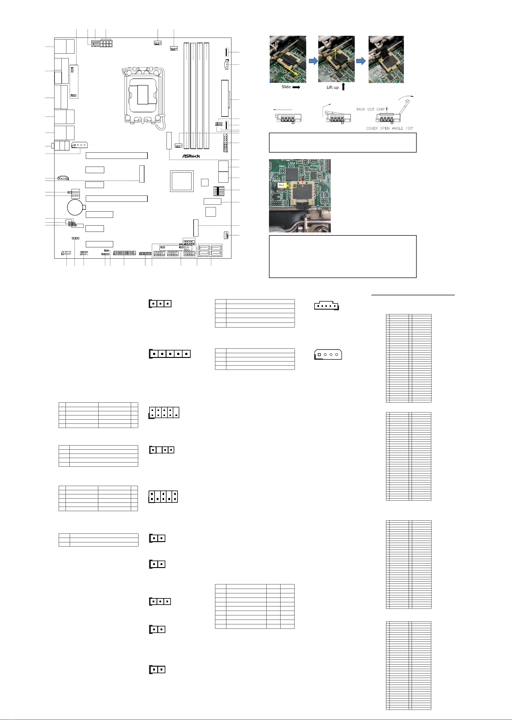
Installation of ROM Socket
* Do not apply force to the actuator cover after ic inserted.
* Do not apply force to actuator cover when it is opening over 120
degree, Otherwise, the actuator cover may be broken.
* The yellow dot (Pin1) on the ROM must be installed at pin1 position of
the socket (white arrow area).
* Make sure the white dot on the ROM is installed outwards of the
socket.
* For further details of how to install ROM, please refer to ASRI website.
Warning: If the installation does not follow as the picture, then it
may cause severe damage to chipset & MB.
* This motherboard supports RS232/422/485 on COM1, 2 ports. Please
refer to the table below for the pin denition. In addition, COM1, 2 ports
(RS232/422/485) can be adjusted in BIOS setup utility > Advanced
Screen > Super IO Conguration. You may refer to our user manual
for details.
COM1, 2 Port Pin Denition
Pin RS232 RS422 RS485
1 DCD, Data Carrier Detect TX- RTX-
2 RXD, Receive Data TX+ RTX+
3TXD, Transmit Data RX+ N/A
4 DTR, Data Terminal Ready RX- N/A
5 GND GND GND
6 DSR, Data Set Ready N/A N/A
7 RTS, Request To Send N/A N/A
8 CTS, Clear To Send N/A N/A
9 No Power/5V/12V N/A N/A
• Auto clear CMOS when system boot improperly.
M.2 Sockets Pin Denition
16 : M.2 Key-M Socket (M2_M1)
20 : M.2 Key-B Socket (M2_B1)
21 : M.2 Key-M Socket (M2_M2)
(For IMB-X1714 Only)
40 : M.2 Key-E Socket (M2_E1)
ATXPWR1
PCIE1
HD_AUDIO1
CMOS
Battery
Top:
Line In
Center:
Line Out
Bottom:
Mic In
Industrial
1
LPT_GPIO1
JGPIO_SET1
JGPIO_PWR1
SPDIF1
1
COM2
VGA1
1
CLRMOS2
CHA_FAN1
PCIE2
CHA_FAN3
ESPI1
1
USB3_5_6
CHA_FAN2
PWR_COM2
1
M2_M1
TB1
1
PCIE5
COM1
HDMI1
Top:
LAN3
USB 3.2 Gen2
T: USB3_2
B: USB3_1
1
CLRMOS1
COM3
PWR_COM3
1
1
SIO_AT1
DACC1
BIOS
ROM
PCIE4
PCIE7
PCIE3
PCIE6
M2_M2
M2_E1
DDR5_A2 (64 bit, 288-pin module)
DDR5_A1 (64 bit, 288-pin module)
DDR5_B2 (64 bit, 288-pin module)
DDR5_B1 (64 bit, 288-pin module)
DP1
Top:
LAN2
T: USB 3.2 Gen2
(USB3_9)
B: USB 3.2 Gen2x2
(TC_U3_7)
Top:
LAN1
USB 3.2 Gen2
T: USB3_4
B: USB3_3
1
PWR_COM1
1
CPU_FAN1
PWR_LOSS1
COM4 COM5
COM6
PWR_COM4
1
PWR_COM6
1
PWR_COM5
SIM1
1
BUZZ2
12345
7
8
9
10
12
6
20
19
15
13
25 24 23
22
21
33 32 31 30 29 28 27 26
37
36
35
34
38
14
39
PCIE_PWR1
42
41
40
43
44
PSU_SMB1
1
SATA3_4
SATA3_5
SATA3_6
SATA3_7
1
PWR_BAT1
45
46
47
1
CI1CI2
11
USB2_13
1 1
17
16
18
M2_B1
PWRB TN PLE D
RESE T HDLE D
1
1
1
1
1
1
1
1
1
1
1
1
11
I225_LED3
ATX12V1
PS2_KB_MS1
1
1
USB2_12
PANEL1
1
SATA3_0SATA3_2
SATA3_1SATA3_3
1
1111
1
1
1
1
1
USB2_10_11
1
I225_LED3
1
1
1
I225_LED2
I225_LED1
1
1
• Only supported by chargeable battery.
Pin Signal Name Pin Signal Name
1 NA 2 +3.3V
3 GND 4 +3.3V
5 GND 6 FuLL_Card_Power_o󰀨
7 USB_D+ 8 W_DISABLE
9 USB_D- 10 WWAN_LED#
11 GND
20 NA
21 GND 22 NA
23 NA 24 NA
25 NA 26 NA
27 GND 28 NA
29 USB3_RX- 30 UIM_RESET
31 USB3_RX+ 32 UIM_CLK
33 GND 34 UIM_DATA
35 USB3_TX- 36 UIM_PWR
37 USB3_TX+ 38 NA
39 GND 40 NA
41 PERn0 42 NA
43 PERp0 44 NA
45 GND 46 NA
47 PETn0 48 NA
49 PETP0 50 PERST#
51 GND 52 CLKREQ#
53 PEFCLKn 54 WAKE#
55 PEFCLKp 56 NA
57 GND 58 NA
59 NA 60 NA
61 NA 62 NA
63 NA 64 NA
65 NA 66 NA
67 NA 68 NA
69 NA 70 +3.3V
71 GND 72 +3.3V
73 GND 74 +3.3V
75 NA
Pin Signal Name Pin Signal Name
1 GND 2 +3.3V
3 GND 4 +3.3V
5 PERn3 6 NA
7 PERp3 8 NA
9 GND 10 LED
11 PETn3 12 +3.3V
13 PETp3 14 +3.3V
15 GND 16 +3.3V
17 PERn2 18 +3.3V
19 PERp2 20 NA
21 GND 22 NA
23 PETn2 24 NA
25 PETp2 26 NA
27 GND 28 NA
29 PERn1 30 NA
31 PERp1 32 NA
33 GND 34 NA
35 PETn1 36 NA
37 PETp1 38 DEVSLP
39 GND 40 SMB_CLK
41 PERn0 42 SMB_DATA
43 PERp0 44 NA
45 GND 46 NA
47 PETn0 48 NA
49 PETp0 50 PERST#
51 GND 52 CLKREQ#
53 PEFCLKn 54 WAKE#
55 PEFCLKp 56 NA
57 GND 58 NA
59 60
61 62
63 64
65 66
67 NA 68 NA
69 PEDET 70 +3.3V
71 GND 72 +3.3V
73 GND 74 +3.3V
75 GND
Pin Signal Name Pin Signal Name
1 GND 2 +3VSB
3 USB_D+ 4 +3VSB
5 USB_D- 6 NA
7 GND 8 NA
9 CNV_WGR_D1- 10 CNV_RF_RESET
11 CNV_WGR_D1+ 12 NA
13 GND 14 MODEM_CLKREQ
15 CNV_WGR_D0- 16 NA
17 CNV_WGR_D0+ 18 GND
19 GND 20 NA
21 CNV_WGR_CLK- 22 CNV_BRI_RSP
23 CNV_WGR_CLK+
32 CNV_BGI_DT
33 GND 34 CNV_RGI_RSP
35 PETp 36 CNV_BRI_DT
37 PETn 38 NA
39 GND 40 NA
41 PERp 42 NA
43 PERn 44 NA
45 GND 46 NA
47 PEFCLKp 48 NA
49 PEFCLKn 50 SUSCLK
51 GND 52 PERST0#
53 CLKREQ# 54 W_DISABLE1#
55 WAKE# 56 W_DISABLE2#
57 GND 58 SMB_DATA
59 CNV_WT_D1- 60 SMB_CLK
61 CNV_WT_D1+ 62 NA
63 GND 64 CLKIN_XTAL_LCP
65 CNV_WT_D0- 66 NA
67 CNV_WT_D0+ 68 NA
69 GND 70 NA
71 CNV_WT_CLK- 72 +3VSB
73 CNV_WT_CLK+ 74 +3VSB
75 GND
29 :
Digital Input / Output
Default Value
Setting (JGPIO_SET1)
1-2 : Pull-High (Default)
2-3 : Pull-Low
30 :
Digital Input/Output Power Select
(JGPIOPWR) (JGPIO_PWR1)
1-2 : +12V
2-3 : +5V
(Default)
3-4 : +5V
4-5 : GND
31 :
USB 2.0 Header (
USB2_10_11)
1
2
9
10
Pin Signal Name Signal Name Pin
1 USB_PWR USB_PWR 2
3 P- P- 4
5 P+ P+ 6
7 GND GND 8
9 DUMMY 10
32 : SPDIF Header (SPDIF1)
Pin Signal Name
1 +5V
2
3 SPDIF OUT
4 GND
14
33 :
Front Panel Audio Header (HD_AUDIO1)
Pin Signal Name Signal Name Pin
1 MIC2_L GND 2
3 MIC2_R 4
5 OUT2_R MIC_RET 6
7 J_SENSE 8
9 OUT2_L OUT_RET 10 19
210
34
: Buzzer Header (BUZZ2)
1 2
1 2
Pin Signal Name
1 +5V
2 BUZZ_LOW
35 :
Clear CMOS Headers
CLRMOS2
Open : Normal (Default)
Short : Auto Clear CMOS (Power O󰀨)
CLRMOS1
1-2 : Normal (Default)
2-3 : Clear CMOS
1 2
1 2
1 2 3
36 : PWR_BAT1
Open : Normal (Default)
Short : Charge Battery
1 2
1 2
38 : DACC1
Open : No ACC
Short : ACC (Default)
1 2
1 2
40 :
5-pin Thunderbolt AIC Connector (TB1)
Pin Signal Name
1TB_FRC_PWR
2 TBCIO_PLUG_EVENT_R2
3SLP_S3#
4TBT_SLP_S5_S4#
5GND
15
41 : PCIe Power Connector (PCIE_PWR1)
Pin Signal Name
1 N/A
2 GND
3 GND
4 +12V
1 4
• The connector provides additional power for PCIe slot devices.
42 :
Audio Jacks
Blue - Line In
Green - Line Out
Pink - Mic In
43 :
Top : RJ45 LAN Port (LAN1) (Supports PoE)
Bottom : USB 3.2 Gen2 Ports (USB3_3_4)
44 :
Top : RJ45 LAN Port (LAN2)
Middle : USB 3.2 Gen2 Port (USB3_9)
Bottom : USB 3.2 Gen2x2 Type-C Port
(TC_U3_7)
1 3
1 5

Other manuals for IMB-1714

1

This manual suits for next models

1

Other ASRock Industrial Motherboard manuals

ASRock Industrial IMB-R1000 User manual

ASRock Industrial

ASRock Industrial IMB-R1000 User manual

ASRock Industrial IMB-X1314 Service manual

ASRock Industrial

ASRock Industrial IMB-X1314 Service manual

ASRock Industrial IMB-1003 User manual

ASRock Industrial

ASRock Industrial IMB-1003 User manual

ASRock Industrial SOM-P104 Service manual

ASRock Industrial

ASRock Industrial SOM-P104 Service manual

ASRock Industrial SBC-350 User manual

ASRock Industrial

ASRock Industrial SBC-350 User manual

ASRock Industrial IMB-1230 User manual

ASRock Industrial

ASRock Industrial IMB-1230 User manual

ASRock Industrial IMB-X1314 User manual

ASRock Industrial

ASRock Industrial IMB-X1314 User manual

ASRock Industrial 4X4-7735U/D5 Service manual

ASRock Industrial

ASRock Industrial 4X4-7735U/D5 Service manual

ASRock Industrial IMB-1712 User manual

ASRock Industrial

ASRock Industrial IMB-1712 User manual

ASRock Industrial IMB-1234 Service manual

ASRock Industrial

ASRock Industrial IMB-1234 Service manual

ASRock Industrial IMB-V2000 User manual

ASRock Industrial

ASRock Industrial IMB-V2000 User manual

ASRock Industrial IMB-X1316 User manual

ASRock Industrial

ASRock Industrial IMB-X1316 User manual

ASRock Industrial IMB-1234 User manual

ASRock Industrial

ASRock Industrial IMB-1234 User manual

ASRock Industrial IMB-X1316 Service manual

ASRock Industrial

ASRock Industrial IMB-X1316 Service manual

ASRock Industrial IMB-1314 Service manual

ASRock Industrial

ASRock Industrial IMB-1314 Service manual

ASRock Industrial IMB-1232-WV User manual

ASRock Industrial

ASRock Industrial IMB-1232-WV User manual

ASRock Industrial SBC-370 User manual

ASRock Industrial

ASRock Industrial SBC-370 User manual

ASRock Industrial IMB-1231 Service manual

ASRock Industrial

ASRock Industrial IMB-1231 Service manual

ASRock Industrial IMB-1314 Service manual

ASRock Industrial

ASRock Industrial IMB-1314 Service manual

ASRock Industrial IMB-1235 Service manual

ASRock Industrial

ASRock Industrial IMB-1235 Service manual

ASRock Industrial IMB-1316 User manual

ASRock Industrial

ASRock Industrial IMB-1316 User manual

ASRock Industrial SOM-P104 User manual

ASRock Industrial

ASRock Industrial SOM-P104 User manual

ASRock Industrial N3710-NUC IPC User manual

ASRock Industrial

ASRock Industrial N3710-NUC IPC User manual

ASRock Industrial 4X4-R1000M User manual

ASRock Industrial

ASRock Industrial 4X4-R1000M User manual

Popular Motherboard manuals by other brands

ASROCK PHANTOM GAMING 4 B550 user manual

ASROCK

ASROCK PHANTOM GAMING 4 B550 user manual

ST STEVAL-PCC010V1 user manual

ST

ST STEVAL-PCC010V1 user manual

Asus P8Z77-V LE PLUS user guide

Asus

Asus P8Z77-V LE PLUS user guide

Texas Instruments PGA308EVM user guide

Texas Instruments

Texas Instruments PGA308EVM user guide

MSI K7T266 Pro-R user guide

MSI

MSI K7T266 Pro-R user guide

ASROCK IMB-184-PY user manual

ASROCK

ASROCK IMB-184-PY user manual

Texas Instruments TLV3601EVM user guide

Texas Instruments

Texas Instruments TLV3601EVM user guide

Biostar Z490GTN manual

Biostar

Biostar Z490GTN manual

Asus P4S800-MX SE manual

Asus

Asus P4S800-MX SE manual

ECS B75H2-M user manual

ECS

ECS B75H2-M user manual

Asus CUC2000-M user manual

Asus

Asus CUC2000-M user manual

Texas Instruments DP83867 user guide

Texas Instruments

Texas Instruments DP83867 user guide

TYAN Thunder i860 S2603 user manual

TYAN

TYAN Thunder i860 S2603 user manual

ASROCK H81M-HG4 user manual

ASROCK

ASROCK H81M-HG4 user manual

CHAINTECH CT-6SFV user manual

CHAINTECH

CHAINTECH CT-6SFV user manual

Gigabyte 8I945PE-FS user manual

Gigabyte

Gigabyte 8I945PE-FS user manual

ASROCK 939A785GMH128 user manual

ASROCK

ASROCK 939A785GMH128 user manual

NXP Semiconductors FRDM-HB2000-EVM user guide

NXP Semiconductors

NXP Semiconductors FRDM-HB2000-EVM user guide

manuals.online logo
manuals.online logoBrands
  • About & Mission
  • Contact us
  • Privacy Policy
  • Terms and Conditions

Copyright 2025 Manuals.Online. All Rights Reserved.