Suitmate 115V/60Hz Maintenance and service guide


October 7, 2012 115-V 20-Amp 60-Hz Self-Timed Unit
1
TABLE OF CONTENTS
Introduction2
Important Installation Options2
Safety2
SUITMATE® Installation Instructions3
6
7
7
SUITMATE® Utilities Location Diagram8
SUITMATE® Maintenance Instructions9
SUITMATE® Troubleshooting11
Remove / Replace Mechanical Assemblies14
14
14
15
19
21
23
25
27
29
31
33
35
37
41
Replace Electrical Assemblies43
43
45
47
47
SUITMATE® Micro Switch Adjustment Procedure49
SUITMATE® Exploded Drawing50
SUITMATE® Assemblies Chart51
SUITMATE® Parts and Assemblies List52
SUITMATE® Maintenance Log56

October 7, 2012 115-V 20-Amp 60-Hz Self-Timed Unit
2
INTRODUCTION
IMPORTANT INSTALLATION OPTIONS
SAFETY

October 7, 2012 115-V 20-Amp 60-Hz Self-Timed Unit
3
INSTALLATION INSTRUCTIONS
115-V 20-Amp 60-Hz Self-Timed Unit
PROPER LOCATION FOR THE SUITMATE® UNIT
PROPER WALL MOUNTING OF THE SUITMATE® UNIT
WARNING!
Anchors in drywall are not sufcient to mount the SUITMATE® unit.
Locating and Securing the Wall Mount Bracket to the Wall
WARNING!
The Wall Mount Bracket must be level after it is secured to the wall.
CHECK WITH LEVEL
USE APPROPRIATE FASTENERS
FOR YOUR APPLICATION
TO WALL

October 7, 2012 115-V 20-Amp 60-Hz Self-Timed Unit
4
Mounting the SUITMATE® Unit to the Wall
Note: Several holes in the lower mounting bracket may be obstructed by the GFCI Cover. Remove the GFCI
cover to provide access to these holes.
SUITMATE® UNIT
(front)
WALL MOUN
T
BRACKET
USE APPROPRIATE ANCHORS AND
FASTENERS TO MOUNT THE UNIT
FOR YOUR SPECIFIC INSTALLATION
CUTAWAY VIEW OF SUITMATE® UNIT
FLOOR
PRESS HERE TO FIRMLY
SET SUITMATE® UNIT
WALL
WALL
MOUNT
BRACKET
UPPER
BACK
LIP EASE
UNIT
OVER
BRACKET
AND
LOWER
MOUNTING
SCREWS

October 7, 2012 115-V 20-Amp 60-Hz Self-Timed Unit
5
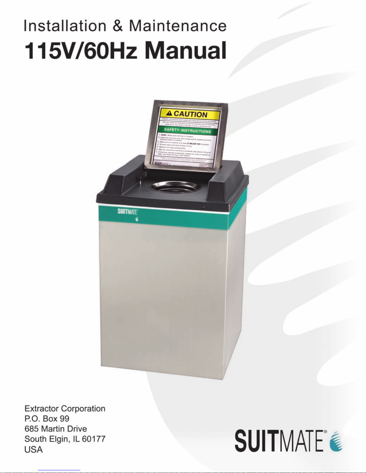
PROPER DRAINAGE FOR THE SUITMATE® UNIT
Note: Strictly follow all applicable local plumbing codes and regulations.
TO A FLOOR DRAIN
WARNING!
The drain tube that comes with the unit must not be removed unless the unit is
connected to an approved wastewater outlet or the factory-supplied tube is
replaced with another tube according to the following instructions.
Replacing the Factory Drain Tube with a Longer Drain Tube
To an Approved Sanitary Waste Line
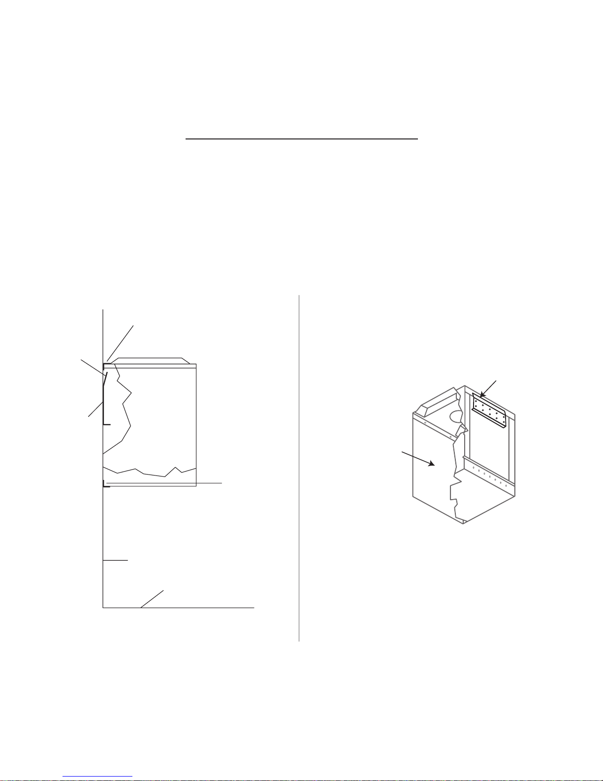
PROPER ELECTRICAL CONNECTIONS FOR THE SUITMATE® UNIT
Note: Strictly follow all applicable local electrical codes and regulations.
WARNING!
Do not route the raceway where wastewater can ow or drip on it.

October 7, 2012 115-V 20-Amp 60-Hz Self-Timed Unit
6
CUSTOMER'S ELECTRICAL SERVICE
115-V / 20-Amp / 60-HZ
BLACK AEC1842
(From Timer To Motor)
BLACK AEC1843
GREEN
SCREW
GFCI IS
"GROUND FAULT CIRCUIT INTERRUPTER"
MOTOR CONTROLLER AND SWITCH
BLACK
AEC1840
WHITE AEC1841
(From Timer To Motor)
COM
N.O.
TIMER
HOT NEU GROUND
GREEN
SCREW
HOT WHITE
HOT NEU
LOAD
BLACK
AEC1815
GFCI
WHITE AEC1813
(From GFCI To Motor)
(From Timer To Micro Switch)
MICRO SWITCH
COMMON
GREEN or GREEN/YELLOW AEC2061
(From GFCI To Motor)
RESET BUTTON, ON
TEST BUTTON, OFF
OPEN
MOTOR
SUITMATE® UNIT
L1 L2
3
2
SUITMATE
®
WIRING DIAGRAM
115-V 20-Amp 60-Hz Self-Timed Unit

October 7, 2012 115-V 20-Amp 60-Hz Self-Timed Unit
7
TESTING AND OPERATION
INSTALLATION TROUBLESHOOTING
FINISHING THE INSTALLATION
POSTING THE WALL SIGN

October 7, 2012 115-V 20-Amp 60-Hz Self-Timed Unit
8
UTILITIES LOCATION DIAGRAM
115-V 20-Amp 60-Hz Self-Timed Unit
WARNING!
This diagram is for reference only! It is not to be used as the sole reference
for installation of the SUITMATE® unit. The installation instructions beginning
on page 3 must be followed explicitly!
Wall
Sign
Suggested location
for Internal
Connections of
Customer's
Power Source
upper center hole of
Wall Mount Bracket
The upper center
hole of the Wall
Mount Bracket
has to be located
38 +/- inches
[965 +/- 2 mm]
above the floor.
Centerline of 38 " hole locating
Top of Wall
Sign is
located 60
[1534 +/- 2
mm] above
floor and
centered
over
the (open)
Lid as
shown.
+/-116 inches
38 " [9.5] diameter hole
used to locate the
upper center hole of
the Wall Mount Bracket
Suggested location for
Internal Connection to
Customers' Waste Drain
35
16 [84]
1 [25]
Floor
11 [279]
3 [76]
105
8 [270]
31
2 [89]
7 [178] 4 [102]

October 7, 2012 115-V 20-Amp 60-Hz Self-Timed Unit
9
MAINTENANCE INSTRUCTIONS
115-V 20-Amp 60-Hz Self-Timed Unit
TWICE DAILY
1) Hygienic Wipes
DAILY
1) Inspection
2) Hygienic Cleaning
WARNING!
Never use ammable solvents in or on the SUITMATE® unit.
When cleaning around the unit, be careful not to allow water to splash up under
the unit as this may damage the motor.
3) Flushing

October 7, 2012 115-V 20-Amp 60-Hz Self-Timed Unit
10
MONTHLY
1) Case and Top care
2) Testing the GFCI

October 7, 2012 115-V 20-Amp 60-Hz Self-Timed Unit
11
TROUBLESHOOTING
115-V 20-Amp 60-Hz Self-Timed Unit
Problem: The unit is not working. There is no sound, no hum, and no noise at all when the lid
is depressed.
Problem: The unit is humming when the Lid is depressed, but the Basket is not spinning.
CAUTION!
Make certain the main electrical power to the unit is turned off – and locked out
– before beginning work on the SUITMATE® unit.

October 7, 2012 115-V 20-Amp 60-Hz Self-Timed Unit
12
Problem: The unit is humming as soon as power is engaged and before the Lid is depressed.
Problem: The unit is leaking.
Problem: The GFCI is tripping off every time the unit is run.
CAUTION!
Make certain the main electrical power to the unit is turned off – and locked out
– before beginning work on the SUITMATE® unit.

October 7, 2012 115-V 20-Amp 60-Hz Self-Timed Unit
13
Problem: The GFCI is tripping off at random times, no specic patter or reason.
Problem: The Basket is still spinning when you lift the Lid.
Please take the unit out of service immediately
Problem: The unit will run but takes a long time to reset before being able to run again.
Problem: The unit is making excessive noise when it is running.
If the above steps and suggestions have not resolved your problem, please contact Extractor Corporation at:
(Telephone) 800-553-3353, (Fax) 847-742-3552, or (E-mail) [email protected].
CAUTION!
Make certain the main electrical power to the unit is turned off – and locked out
– before beginning work on the SUITMATE® unit.

October 7, 2012 115-V 20-Amp 60-Hz Self-Timed Unit
14
MECHANICAL ASSEMBLIES
115-V 20-Amp 60-Hz Self-Timed Unit
Note: Always turn off the power at the circuit breaker – place a lockout tag on the circuit breaker panel indicating that
the breaker is not to be turned on except by authorized personnel – and disconnect the electrical connections before
doing any work on the SUITMATE® unit. Simply turning off a switch is NOT enough. Use only proper tools, test equip-
ment, and work practices when servicing the SUITMATE® unit.
If there are questions concerning proper tools, equipment or practices, please call the factory for recommendations at:
(Telephone) 800-553-3353, (Fax) 847-742-3552 or (Email) [email protected].
Due to critical tolerances, use only specied replacement parts. (See the individual sections in this manual.)
Some disassembly and assembly procedures have not been included, as the procedures seem to be self-evident.
REMOVE SUITMATE® UNIT FROM THE WALL MOUNT BRACKET
Do This FIRST prior to performing any electrical or mechanical maintenance.
CAUTION!
Make certain the main electrical power to the unit is turned off – and locked out
– before beginning work on the SUITMATE® unit.
EXTERNAL ELECTRICAL SERVICE
EXTERNAL PLUMBING SERVICE
INTERNAL ELECTRICAL AND PLUMBING SERVICE
REINSTALL THE SUITMATE® UNIT
CAUTION!
Make certain the main electrical power to the unit is turned off – and locked out
– before beginning work on the SUITMATE® unit.
Note: Make certain the unit is level. If it is not level, remove the unit, adjust the Wall Mount Bracket and re-hang the
unit. A level installation is necessary to minimize vibration and insure proper drainage of wastewater.

October 7, 2012 115-V 20-Amp 60-Hz Self-Timed Unit
15
SUB-TOP ASSEMBLY
CASE ASSEMBLY
EC12
EC 6
(6) AEC 1205
WITH LID (1) EC 4
TOP ASSEMBLY
(2) AEC 1605
BLACK ALUMINUM
BLACK BRAKE TIP
POP RIVET
REMOVE THE TOP AND SUB-TOP ASSEMBLIES
Do This FIRST
REMOVE TOP ASSEMBLY
Note: Make certain the drill bit does not reach a depth of more than ½-inch to avoid damaging the
Black Plastic Liner.

October 7, 2012 115-V 20-Amp 60-Hz Self-Timed Unit
16
ALUMINUM POP RIVET
(3) AEC1240
SUB-TOP ASSEMBLY
EC6
TURNBUCKLE NUT
RISER SHUTTLE
AEC2020
RISER CABLE
EC8
(1) AEC1807
SUB-TOP GASKET
(1) AEC1352
TURNBUCKLE

October 7, 2012 115-V 20-Amp 60-Hz Self-Timed Unit
17
REMOVE SUB-TOP ASSEMBLY
Note: Make certain the drill bit does not reach a depth of more than ½-inch to avoid damaging the
plastic liner.
REPLACE SUB-TOP ASSEMBLY
Note: Make sure that the lip of the Sub-Top is outside the Case.
REPLACE TOP ASSEMBLY
Note: Check the Micro Switch alignment by following the MICRO SWITCH ADJUSTMENT PROCEDURE
section (Page 49) in this manual.

October 7, 2012 115-V 20-Amp 60-Hz Self-Timed Unit
18
LID (1) CEC1402
(4) AEC1410
S.S. POP RIVET
S.S. NUT (1) AEC1804
(1) BEC1403
HINGE PIN, LEFT
(1) AEC1405
S.S. ACTUATOR SCREW
BLACK O-RING (2) AEC1416
(1) AEC1704
S.S. LOCKWASHER
(1) BEC1404
HINGE PIN, RIGHT
AEC 1205 (6) BLACK RIVET
AEC1235 - TIMED UNIT
INSTRUCTIONS (1)
LID OPERATING
TOP ASSEMBLY (1) EC2
AEC1234
LABEL (1)
LIFT LID
This manual suits for next models
1
Table of contents
Popular Extender manuals by other brands

GYS
GYS NOMAD POWER 300 Translation of the original instructions

Green-Box Technology
Green-Box Technology ET-HC0101-T user manual

Guntermann & Drunck
Guntermann & Drunck DP-Vision-IP Installation and operation

Amped Wireless
Amped Wireless REB175P user guide

Creative
Creative BT-W1 manual

netsys
netsys NB-301A user manual