5.2 Structure of the menu system
5.3 Menu list
6. Supply / changing the batteries
The digital pressure gauge is supplied by two 3.6 V-lithium-
batteries (Type 1/2 AA). Stored values/parameters are also
kept after changing the batteries.
If the symbol for low batteries is indicated in the display, it is
necessary to replace them as soon as possible with two
new ones of the same type in order to ensure a good
readability of the values. This has only to be done in
switched-off condition.
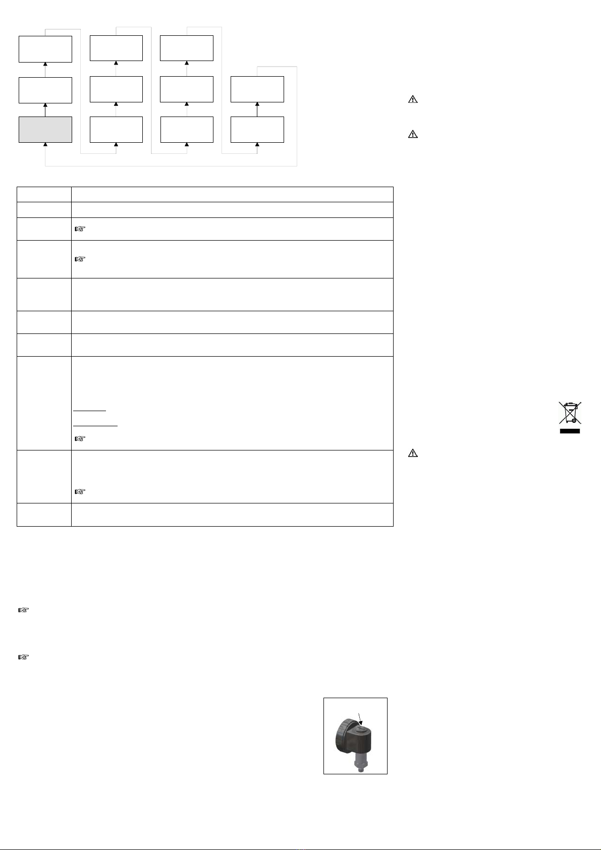
The battery case is located under the black, circular plastic
cap on the top of the housing. To change the batteries go
ahead as follows:
- turn the plastic cap 45° anti
clockwise by a coin (e.g. 2 €
coin) as far as possible
- hold the count tight and lever
the plastic cap out of the
housing with help of the
count
- take the cap off and change
the batteries
- lock the device after that
properly.
!An incorrect usage may cause a leak out of batteries
and so a damage the device!
!Never combine batteries of different types or old with
new ones.
!Make sure that the batteries are connected correctly
with the corresponding contacts in the battery tray.
!Never try to charge batteries, demount them, or short-
circuit them.
!Keep the batteries away from heat and unshielded
flame.
7. Placing out of service
WARNING! When dismantling the device, it must
always be done in the depressurized and currentless
condition! Check also if the medium has to be drained
off before dismantling!
WARNING! Depending on the medium, it may cause
danger for the user. Comply therefore with adequate
precautions for purification.
8. Maintenance
In principle, this device is maintenance-free. If desired, the
housing of the device can be cleaned when switched of
using a damp cloth and non-aggressive cleaning solutions.
Depending on the measuring medium, however, the
diaphragm may be polluted or coated with deposit. If the
medium is known for such tendencies, the user has to set
appropriate cleaning intervals. After placing the device out
of service correctly, the diaphragm can usually be cleaned
carefully with a non-aggressive cleaning solution and a soft
brush or sponge. If the diaphragm is calcified, it is
recommended to send the device to SUKUfor
decalcification. Please read therefore the chapter “Repair”
below.
!An incorrect cleaning can cause irreparable damages
on diaphragm. Never use spiky objects or pressured air
for cleaning the diaphragm.
9. Service / Repair
Before every return of your device, whether for recalibration,
decalcification, modifications or repair, it is necessary to
contact us to ensure a fast handling of your request. Please
Include the number of devices sent and request a RMA.
Then clean the device and pack it shatterproof before send
it to SUKUindicating the RMA.
10. Disposal
The device must be disposed according to the
European Directives 2002/96/EG and
2003/108/EG (on waste electrical and electronic
equipment) Waste of electrical and electronic
equipment may not be disposed by domestic
refuse!
WARNING! Depending on the measuring medium,
deposit on the device may cause danger for the user
and the environment. Comply with adequate
precautions for purification and dispose of it properly.
11. Warranty conditions
The warranty conditions are subject to the legal warranty
period of 24 months from the date of delivery. In case of
improper use, modifications of or damages to the device, we
do not accept warranty claims. Damaged diaphragms will
also not be accepted. Furthermore, defects due to normal
wear are not subject to warranty services.
12. Declaration of conformity / CE
The delivered device fulfils all legal requirements. The
applied directives, harmonised standards and documents
are listed in the EC declaration of conformity, which is
available online at: http://www.bdsensors.com/products/
download/certificates.
Additionally, the operational safety is confirmed by the CE
sign on the manufacturing label.
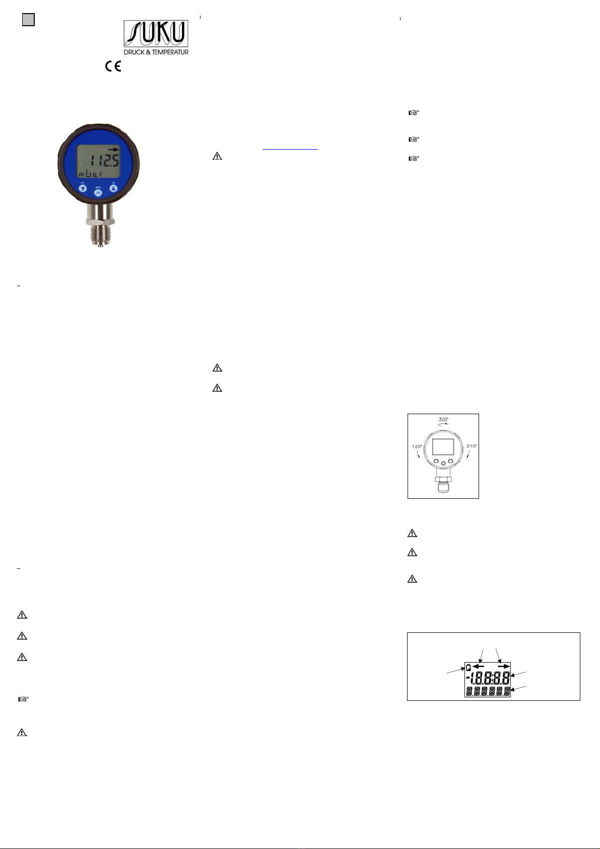
1 LOWER Displaying of the lower range
This value was determined on the order and cannot be changed.
2 UPPER Displaying of the upper range
This value was determined on the order and cannot be changed.
3 DECIMA Setting of the decimal point position
Depending on the nominal pressure range and on the set unit, only a limited number of positions after
the decimal point can be displayed.
4 UNIT Setting of the pressure unit
Permissible units: bar, mbar, psi, InHg, cmHg, mmHg, hPa, kPa, MPa, mH2O.
Along with the unit, the decimal point position has probably to be changed in order to get a correct
indication of the measured value. Besides, depending on the nominal pressure range, perhaps not all
available units can be used.
5 SW OFF Configuration of the switch-off automatic
Meaning of the permissible number:
"0": switch-off automatic is turned off
"1" – "5": automatic switch-off in 1 to 5 minutes
6 P MIN Minimum pressure display
▼–button: puts the current pressure as minimum value
▲–button: puts the value on zero
7 P MAX Maximum pressure display
▼–button: puts the current pressure as maximum value
▲–button: puts the value on zero
8 CAL ZP Calibration of initial point
If you detect a shifting of the measured value deviating from the offset, the display can be re-calibrated. For
this, a pressure reference is necessary if the offset differs from the ambient pressure. The used pressure
must be identical to the starting point of the pressure measuring range. For reading the new pressure into the
device, push the ▲button.
Please note the following diviation:
-1 … x bar: the offset is calibrated at -0.9 bar; during calibration we checked whether the device will be within
tolerance at -1 bar (in theory); for re-calibration a pressure reference of -0.9 bar is necessary
0 … x bar abs.: the offset is calibrated at 0.1 bar abs.; during calibration we checked whether the device will
be within tolerance at 0 bar abs.; for re-calibration a pressure reference of 0.1 bar is necessary
If the re-calibration leads to a worsening of the original calibration, e. g. as a result of a defect pressure
reference, the defaults can be re-set by the menu item "LD FAC" according to your order
9 CAL EP Calibration of end point
If you detect a shifting of the measured value deviating from the end point, the display can be re-calibrated.
For this, a pressure reference is necessary if the offset differs from the ambient pressure. The used pressure
must be identical to the end point of the pressure measuring range. For reading the new pressure into the
device, push the ▲button.
If the re-calibration leads to a worsening of the original calibration, e. g. as a result of a defect pressure
reference, the defaults can be re-set by the menu item "LD FAC" according to your order.
10 LD FAC Load defaults
To load the defaults you have to push the ▲–button. After the action "LOADED" and "OK" appears in the
display for a short time. The configuration mode will be left automatically.
- ▲/ on button: with this button you turn the device on; in the operating mode you move forward in the menu system or
increase the displayed value
- ▼/ off button: with this button you turn the device off; in the operating mode you move backwards in the menu system or
decrease the displayed value
- OK-button: with this button you enter the operating mode; besides, it is used to activate the different menu items and to
confirm the set values
To configure the different menu items, set the desired values by pushing the "▼" or "▲" buttons. Confirm the setting with the „OK“
button and the menu item will start blinking to indicate that you can start the configuration.
To save the configured values or to leave a menu item, you also have to push the “OK” button.
Changes of the adjustable parameters become only effective after pushing the OK button and leaving the menu item. After
leaving the menu system, all parameters will be checked against each other and in reference to the characteristics of the de-
vice. If the message "OK" appears in the display for some seconds, the configuration was successfully. If the message "ER-
ROR" appears, at least one of the set values is out of the permissible range. For example, an error will occur if a device with
a nominal pressure range of 400 bar should be set on 4 positions after the decimal point. If an error has been detected, the
lastly runnable parameters will be set again.
After configuring the unit, the conversion of the pressure range (in menus UPPER und LOWER) into the new unit will only
occur after leaving the complete menu system. Besides, depending on the number of displayed figures of the respective
nominal pressure range, probably not all available units (in menu UNIT) can be used.
Display mode
(measured value is
displayed)
Menu 7: P MAX
Maximal pressure
display
Menu 6: P MIN
Minimal pressure
display
Menu 5: SW OFF
Switch-off
automatic
Menu 4: UNIT
Unit
Menu 3: DECIMA
Decimal point
position
Menu 2: UPPER
Indication of
upper range
Menu 1: LOWER
Indication of
lower range
Menu 8: CAL ZP
Calibration of
starting point
Menu 9: CAL EP
Calibration of
end point
Menu 10: LD FAC
Load defaults
plastic cap above
battery case
Fig. 4 battery case