SUMED Integrity User manual

®
Sumed International (UK) Ltd. Integrity House, Units 1-2 Graphite Way, Hadfield, Glossop, Derbyshire SK13 1QH
SPECIFICATIONS:
Bed Overall 215 cm long x 103.5 cm wide
Mattress Support Platform 201 cm long x 88 cm wide
Underbed Clearance 26.5 cm to Mattress Support Platform
Folded Bed Dimension 125 cm High x 103.5 cm x 44 cm
Weight of Bed Without Side Rails 85 kg
Mattress Sizes :
LENGTH – 197 cm - 201 cm
WIDTH – 88 cm - 91 cm
DEPTH – 12.5 cm - 22.5 cm
Max UserWeight 195 kg
Safe Working Load 230 kg
StorageTemp +5°C to +40°C

INTEGRITY® UNIQUE MOTORISED FOLDING AND EXTENDING ELECTRIC BED
Maximum User Weight195kg (30.7 stones)
Homecare Electric Bed
User Manual


Please Read
Manufacturer information:
Contents
3
1. Introduction
I. A brief overview
II. Specication & Function
Page 4
2. Important Safety Information
I. General Safety Information
Page 5-6
4. Motorised Operation
I. Motorised extension (Unfolding the bed)
II. Fitting the Side Rails
III. Removing the Side Rails
IV. Motorised folding
V. Bed Positions
Page 9 -12
3. Control System Overview
I. Actuator System Overview
II. Actuator System Connections
III.Standard Handset Functions
IIII. Locking Handset Functions
Page 7-8
5. Warranty, Care & Maintenance
I. Warranty
II. Care & Maintenance
III. Cleaning and decontamination
IIII. Periodic Inspection and Maintenance
Page 13
6. Troubleshooting & Spare parts
I. Troubleshooting
II. Spare parts
Page14
Integrity Homecare Electric Bed is a Class I Medical Device.
The Manufacturer of the Product is:
Sumed International (UK) Ltd
Integrity House, Units 1-2 GraphiteWay,
Hadeld, Glossop, Derbyshire SK13 1QH England
Tel: +44 (0)1457 890980
Fax: +44 (0)1457 890990
e-mail: [email protected]
website: www.sumed.co.uk
This manual has been produced using information
available at the time of printing with regard to
construction and functionality of the Integrity Homecare
Electric Bed.
Sumed reserve the right to make changes due to
technical developments or improvements.
©Sumed 2014
GB Patent Pending
Homecare Electric Bed
Thank you for choosing the Integrity Homecare Electric Bed.
This product complies with EN60601-1 & EN60601-2-52.
Before use:
1. Check that nothing has been damaged during
shipping.
2. Read this user manual including all safety
information before operation.
3. Keep the original packaging and if the bed doesn’t
work or is damaged on receipt, then contact your
supplier as soon as possible.

1. Introduction to Integrity SS888-FM
I. A brief overview:
3 YEAR WARRANTY SUBJECT TO COMPLIANCE WITH OPERATING INSTRUCTIONS
• All mattress support frames are made of powder coated steel (colour - light cream)
• 24V DC actuator systems. Voltage:240V/50Hz
• Head and foot board are made of scratch resistant wooden board
• Mattress support frames are made of powder coated steel (colour - light cream)
• Two IV pole sockets & two lifting pole sockets are incorporated in to the mattress support frames
II. Specication & Function:
• Overall size: Length 215cm Width 103.5cm
• 24V DC actuator systems. Voltage: 240V/50Hz
• Max user weight capacity: 195kg (30.7 stone)
• Bed height adjustable from 30 to 70cm
• Back lifting angle 0-73°
• Knee lifting angle 0-35°
• Trendelenburg and reverse Trendelenburg angle 0-12°
• High quality 4" braking castors
• Two IV pole sockets and two lifting pole sockets
• Folded Bed size: Length 103.5cm Width 44cm Height 125cm
• Low noise and IP 54 protection Control System
Detachable head board
4" Braking Castors
Detachable foot board
Head Hi – Low Actuator
Foot Hi – Low Actuator
Leg Break Actuator
Handset
4

!
2. Important Safety Information.
I. General Safety infomation
If you are unsure about any aspect of operating the Integrity Homecare Electric Bed please consult your
supplier or Sumed International (UK) Ltd.
The Integrity Homecare Electric Bed is intended for continuous use where required.
The Integrity Homecare Electric Bed should never be operated by anyone under the age of 12, due to the risk
of injury through crushing. Any children visiting a patient should be supervised at all times.
PATIENTS TALLER THAN 6’ 5” (1.95m) OR HEAVIER THAN 195kg (30.7st) SHOULD NOT USE THIS BED
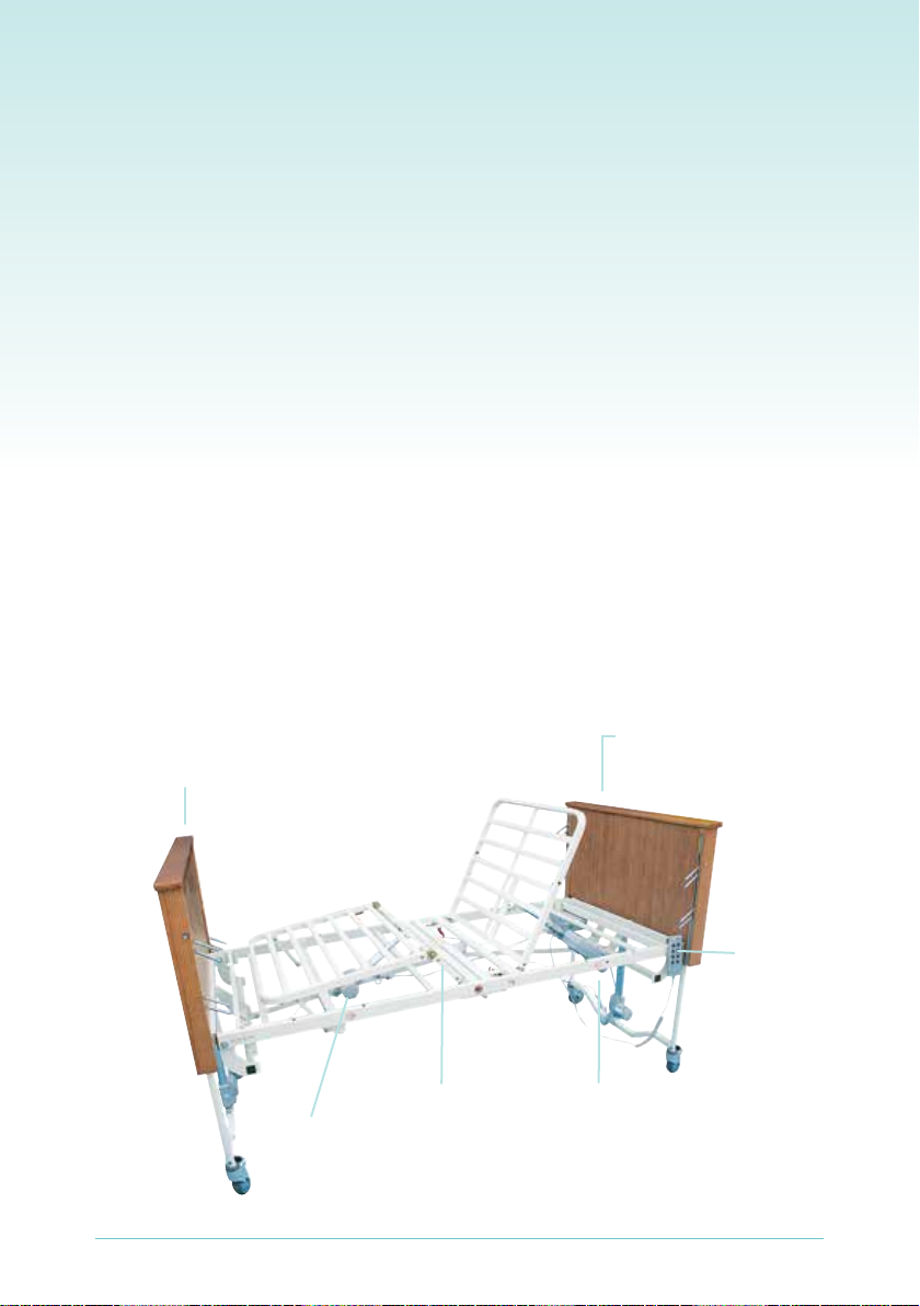
Incompatible mattresses can create hazards – mattress sizes that can be used with the bed:
LENGTH – 197cm - 201cm
WIDTH – 88cm - 91cm
DEPTH – 12.5cm - 22.5cm
Incompatible Side Rails can create hazards – ONLY USE THE SIDE RAILS SUPPLIED WITH THE BED
If replacement side rails are required only use genuine Sumed replacement parts.
The side rails should always be used when the patient is unattended with the bed in the lowest position in
order to reduce risk of injury due to falls.
This manual must be read by anyone assembling or operating the bed. Failure to do so may result in
fatal injury or damage that will not be covered by the warranty.
WARNING: II. To avoid injury or damage when setting up or repairing the bed
A. The power supply should be 240V. Please check power supply prior to use. If in doubt consult a qualied
technician
B. To reduce the risk of electrical shock, please do not remove the control box, actuator and handset without
a quailed technician
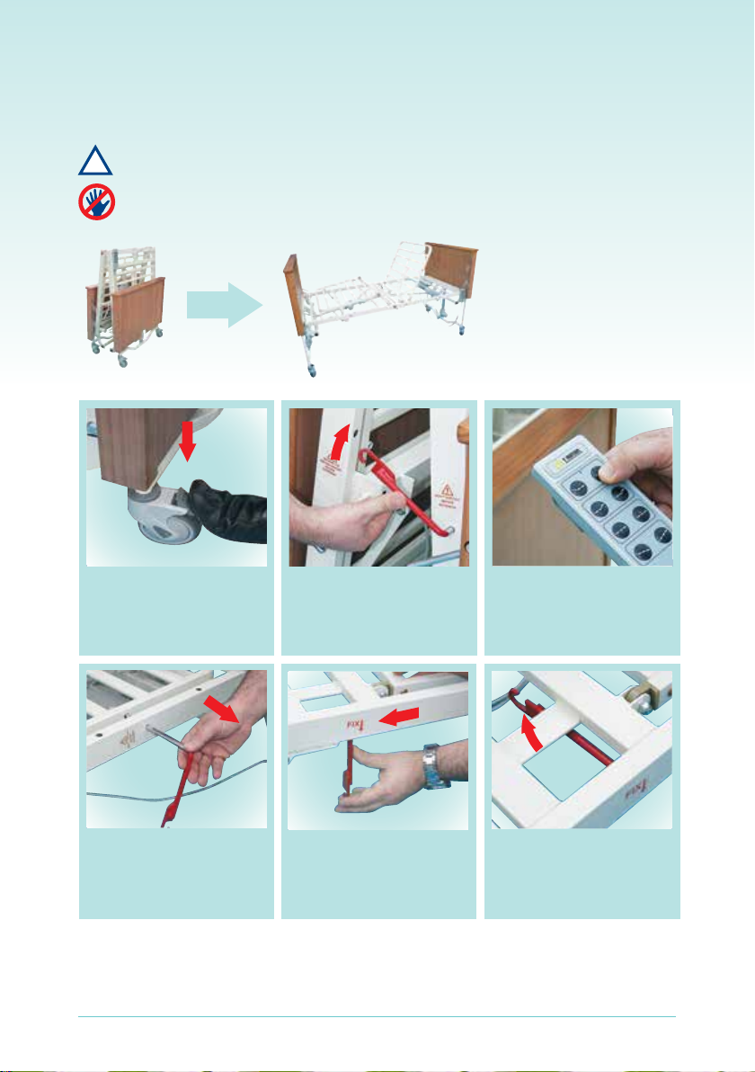
C. Lock all castors before using bed
D. Keep all moving parts clear of obstruction
E. Refer to instructions located in this manual for cleaning and maintainance
F. Do not use abrasives to clean painted surfaces
G. Be aware of moving, telescoping, and rotating parts when positioning the bed. Watch for pinch points.
Keep ngers, arms, legs, and objects clear of bed when any mechanism is in motion. Make sure all persons
and objects are clear of the bed when raising or lowering the bed. Do not place any body parts into the
frame while operating the bed
H. Make sure there is nothing under the bed to interfere with bed operations. Ensure that the mains cable
cannot be run over by items such as cleaning or lifting equipment i.e. hoists
I. Remove power supply and battery before working on the actuator control system
J. Make sure the cord from the control module and the cord from the handset are clear of castors before
operating and do not allow either of these cords to get caught in the moving parts of the bed
K. Do not operate this device if these cables and the associated parts are cut, frayed or loosely connected
!
5

!
Important Safety Information Cont.
WARNING: III. To avoid injury or damage when operating the bed
A. Be aware of moving, telescoping, and rotating parts when positioning the bed. Watch for pinch points.
Keep ngers, arms, legs, and objects clear of bed when any mechanism is in motion
Make sure all persons and objects are clear of the bed when raising or lowering the bed. Do not place arms
or head into the frame while operating
B. Always place bed in a horizontal position when transferring the patient to or from the bed
C. Ensure the head and foot end are correctly located before placing the patient in a horizontal position
D. Always raise the side rails whenever the patient is lying on the bed in the horizontal position
E. Make sure release pins are fully engaged when side rails are raised to highest position
F. The mattress should be suciently wide enough to prevent any part of the patient’s body from falling
between the side rails and the mattress
G. Do not allow the patient to sit on the bed when it is in the highest horizontal position. Lower the bed
before allowing patient to sit on the bed. Never sit or lean on the head or foot end of bed
H. The Trendelenburg position should only be attempted when the patient has been secured in the bed with
both side rails up
I. Do not move the bed when raising or lowering the side rails
J. Do not operate the bed continuously for more than 2 minutes as this may cause the actuator’s thermal
overload to operate and further operation will not be possible for approximately 18 minutes
K. Do not use electrical medical appliances on patients in this bed
L. Do not use this bed in the vicinity of strong electromagnetic elds
M. Do not use the bed in areas where ammable gases or vapours may be present
N. Do not move the bed whilst operating any of the control system functions
Any unauthorised alterations to the Integrity Homecare Electric Bed may result in injury or death
Any unauthorised alterations will void manufacturer’s warranty.
!
6

3. Control Sytem Overview
TiMOTION Actuators MODEL TA7
General Features:
Voltage of motor 24V DC
Maximum load 3500N in push
Max Current 6.0 Amp
Duty Cycle: Max 10% Max 2min/18min
Maximum speed at no load 38.0mm/s
Maximum speed at full load 23.2mm/s
Minimum installation dimension stroke +171mm
Colour: Grey
Certicate EN60601-1, CB and RoHS
Protection Class IP54
TiMOTION Control Box MODEL TC1
Voltage: INPUT 220-240V – 50Hz 700mA
Output: 24V DC .70VA (max)
Number of actuators: 4
Colour : Grey
Duty Cycle: Max 10% Max 2min/18min
Protection Class IP54
Certicate EN60601-1 and FCC
II. Actuator system connections
1) Head Actuator
(Proling function)
2) Leg break Actuator
(Foot End)
3) Hi-Low Actuator
(Head End)
4) Hi-Low Actuator (Foot End)
5) Handset
6) Battery Back up unit
I. Actuator system overview:
Low Voltage 24V DC Control / Actuator System
Low Noise Actuators
Overload Protection
Battery back up available – If battery back up is installed, operation time (in the event of power failure) is
possible up to a maximum of 120 mins (dependant on user weight and total number of operations of the control
system)
7

III. Standard Handset Functions:
IIII. Locking Handset Functions:
Extension*:
Press to unfold the bed
Backrest:
Press to lower backrest
Press to lower knee break
Press to lower bed height
Press to reverseTrendelenburg
Folding*:
Press to fold the bed
Backrest:
Press to raise backrest
Press to raise knee break
Press to raise bed height
Extension*:
Press to unfold the bed
Backrest:
Press to lower backrest
Press to lower knee break
Press to lower bed height
Folding*:
Press to fold the bed
Backrest:
Press to raise backrest
Press to raise knee break
Press to raise bed height
Press to raise back height
locking key
Press to lower back height
*Please Note, these are dual function
controls. The backrest function operates
automatically once the bed is unfolded
and locked into position.
Press to Trendelenburg
8

4. Motorised Operation
I. Motorised Extension (Unfolding the bed):
!
1. Lock both castors at head end of bed –
Labels on head end indicate castors that
require locking
5. Once the bed is completely unfolded
take the red hangers (bars) out of both sides
6. Put the red hangers (bars) through the
locking position (indicated by“Fix” labels)
to the underside of the mattress support
frame
7. Lock the red hangers (bars) in their xed
location by rotating the hangers (bars)
through 90 degrees and locating into their
locking position on the underside of bed
frame
2. Unlock the red hangers (bars) at each side
of the bed
4. Press backrest down key to fully unfold
the bed
3. Ensure there is sucient space
at the foot section of the bed to unfold
the bed to its full extent
PLEASE READ INSTRUCTIONS BEFORE UNFOLDING OR OPERATING THE BED
FAILURE TO DO SO MAY RESULT IN DAMAGE OR INJURY
PLEASE KEEP HANDS CLEAR OF ANY MOVING PARTS TO AVOID ENTRAPMENT AND POSSIBLE INJURY
All the standard functions of the bed can now be operated via the handset
9

4. Motorised Operation
II. Fitting the Side Rails
III. Removing the Side Rails
Simply reverse the above procedure to remove the rails
!
PLEASE READ INSTRUCTIONS BEFORE UNFOLDING OR OPERATING THE BED
FAILURE TO DO SO MAY RESULT IN DAMAGE OR INJURY
PLEASE KEEP HANDS CLEAR OF ANY MOVING PARTS TO AVOID ENTRAPMENT AND POSSIBLE INJURY
1. Unscrew bottom side rail retaining screw
from head or footboard using Phillips
screwdriver
4. Slide side rail carrier ngers and side rails
up to top locking position then replace
lower retaining screw (removed
in step 1)
5. Release side rail carrier ngers and side rails
by pressing release button on side of frame
and gently lower rails to bottom position
Note never drop side rails as this could cause
damage to rails and lower retaining screws
6. Repeat process at opposite end / side of the
bed.
2. Take side rail carrier ngers (both long and
short version) ensuring that carrier ngers
are positioned with angled ends to top.
Insert small carrier nger bracket into large
carrier nger bracket as indicated in picture
3. Take one side rail – Insert side rail carrier
ngers into locations on the end of the side
rail and slide carrier ngers into aluminium
channel on head or footboard (dependant
on end of bed you are working at)
10

1. Lock both castors at head end of bed –
Labels on head end indicate castors that
require locking
4.Insert the red hangers (bars) in both sides
of the bed frame
5. Press the back rest up button to fold the bed 6. Lock the red hangers (bars) on each side
of the bed to secure in the folded postion.
Unlock the castors to move the bed in to
desired postion.
2. Unlock the red hangers (bars) from their
xed locations by rotating the hangers (bars)
through 90 degrees until they hang down
from the underside of the frame
3. Pull the red hangers (bars) out of their
locking position
1. First remove siderails if tted
2. Ensure head section and knee break sections have been fully lowered to horizontal position
3. Ensure bed has been fully lowered
4. Motorised Operation
IV. Motorised Folding
!
PLEASE READ INSTRUCTIONS BEFORE UNFOLDING OR OPERATING THE BED
FAILURE TO DO SO MAY RESULT IN DAMAGE OR INJURY
PLEASE KEEP HANDS CLEAR OF ANY MOVING PARTS TO AVOID ENTRAPMENT AND POSSIBLE INJURY
11

4. Motorised Operation
V. Bed Positions
!
PLEASE READ INSTRUCTIONS BEFORE UNFOLDING OR OPERATING THE BED
FAILURE TO DO SO MAY RESULT IN DAMAGE OR INJURY
PLEASE KEEP HANDS CLEAR OF ANY MOVING PARTS TO AVOID ENTRAPMENT AND POSSIBLE INJURY
1. Backrest lifting / lowering 2. Knee break lifting / lowering 3. Head end Trendelenburg
4. Foot endTrendelenburg 5. Overall height adjustment
12

5. Warranty, Care & Maintenance
I. Warranty
Integrity Home Care Electric Bed is warranted for a period of 3 years from the date of delivery against defects
in materials and workmanship under normal use and service.
This warranty does not apply to damage or defects caused by misuse, incorrect handling or installation by a
non-authorised installer. Damage caused by use in unsuitable environmental conditions or failure to maintain
the product in accordance with user and service instructions is not covered. We do not accept responsibility for
damage and operational breakdowns which are caused by operating errors and non-compliance with this
service manual.
We reserve the right to technical changes within the bounds of further development of the bed covered in this
service manual. Any alteration, modication or repair unless performed by (or authorised in writing by)
Sumed will void this warranty.
II. Care & Maintenance
A. Electronics
1. Check all controls to make sure all controls
function correctly
• Knee break control
• Backrest control
• Hi/Lo
• Trendelenberg / reverse Trendelenburg
2. Check all cables for damaged kinking or frayed wires.
• Power cord
• Knee break actuator cable
• Backrest actuator cable
• Hi/Lo actuator cable
• Handset cable
3. Check to make sure all cables are routed and attached properly
so they do not interfere with or snag any moving parts
4. Check to make sure all plugs are fully inserted or
attached
B. Bed frame and sleeping surface
1. Visually check all welds
• Head section
• Knee section
• Main frame
2. Check joints between sleeping surface sections
for loose fasteners
III. Cleaning and decontamination
Under normal usage the bed may be cleaned with general detergents or alcohol based wipes. Do not use abrasive
creams or bleach on any of the bed parts.
The bed can be jet washed or automatic washing system washed but ALL electrical equipment plus head board,
foot board and side rails MUST BE REMOVED before cleaning by these methods.
IV. Periodic inspection and maintenance
The amount of maintenance required by the bed will be dictated by its use. As a minimum the unit should be
inspected every six months.
1. After two weeks of usage, check all the bolts to be sure that none of them have worked loose and that
all pins are in their normal location and securely fastened. Check all welds
2. Lubricate all slides and pivot points with light grease every 6 months
3. Check all electrical connections for tightness
4. Check all electrical wiring for any frays, kinks and / or deterioration
ANY DISCREPANCIES NOTED DURING INSPECTION MUST BE CORRECTED BEFORE USING THE BED. 13

i.Troubleshooting
II. Spare Parts
6. Troubleshooting & Spare parts
FAULT POSSIBLE CAUSE REMEDY
BED WILL NOT OPERATE
All functions do not work
Mains plug not plugged in
Mains socket is not live
Main power cable is damaged
Fuse in mains plug blown
Control box faulty
Handset faulty
Plug in
Qualied electrician check mains socket
Replace main power cable
Check fuse
Replace control box
Replace handset
INDIVIDUAL FUNCTIONS DO NOTWORK
Hi/Low
Backrest
Knee break
Trendelenburg/ reverse Trendelenburg
Actuator fault on function being operated
Handset fault
Control box
Replace defective part
BED SIDE RAILS JAM Faulty locking button
Damaged side rail carrier ngers
Remove side rails and replace damaged /
faulty part
CASTORS CAN’T BE LOCKED Faulty castor Replace
BED IS DIFFICULT TO MOVE WITH
CASTORS UNLOCKED
Faulty castor / castors Replace
CODE DESCRIPTION
Z012 full length side rails (setx4)
Z012-2 head/foot board (pair)
Z012-5 Side rail carrier ngers long (4)
Z012-6 Side rail carrier ngers short (4)
TA7-2Q-250425 TiMOTION back rest actuator
TA7-2Q-400598 TiMOTION hi – lo actuator
TA7-2Q-100275 TiMOTION knee break / leg rest actuator
TC1-2242 TiMOTION control box
TH2 TiMOTION handset
TH2-SK TiMOTION lockable handset
TBB-2A1 TiMOTION battery back up
TA7 TiMOTION power lead 4m
Z012-8-4IN 4”brake castor
Z012-9 Button & spring –head / foot board lock
Z012-10 Cross bars bed frame
Z012-11 Quick release catch
Z012-12 Side rail lower retaining screw
Z012-13 Side rail plastic end caps
14

IV. Periodic inspection and maintenance
The amount of maintenance required by the bed will be dictated by its use. As a minimum the unit should be
inspected every six months.
1. After two weeks of usage, check all the bolts to be sure that none of them have worked loose and that
all pins are in their normal location and securely fastened. Check all welds
2. Lubricate all slides and pivot points with light grease every 6 months
3. Check all electrical connections for tightness
4. Check all electrical wiring for any frays, kinks and / or deterioration
ANY DISCREPANCIES NOTED DURING INSPECTION MUST BE CORRECTED BEFORE USING THE BED.
Other manuals for Integrity
2
Table of contents