SummerAire SE10I (E) User manual
Other SummerAire Furnace manuals
SummerAire
SummerAire RME 111 User manual

SummerAire
SummerAire SBB100 User manual
SummerAire
SummerAire SLO SERIES User manual
SummerAire
SummerAire SWO User manual
SummerAire
SummerAire SE10B User manual

SummerAire
SummerAire ELECTRIC WARM AIR FURNACE User manual

SummerAire
SummerAire S150 User manual

SummerAire
SummerAire ELECTRIC WARM AIR FURNACE User manual
SummerAire
SummerAire OLM SERIES User manual
SummerAire
SummerAire SBB Operation manual
Popular Furnace manuals by other brands
Unitary products group
Unitary products group AHV8 UH installation manual

VERDER
VERDER CARBOLITE GERO RHF 14/8 Installation, operation and maintenance instructions
Tempstar
Tempstar B Series Service and technical support manual
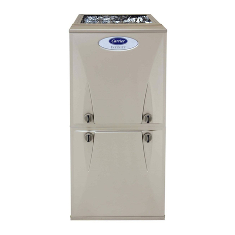
Carrier
Carrier Performance 59SP5A Installation, start-up, operating and service and maintenance instructions

Armstrong
Armstrong EG7H SERIES Installation and maintenance instructions

Payne
Payne PG92ESA Installation, start-up, operating and service and maintenance instructions

NANOE
NANOE Zetasinter Operation manual

SUPREME
SUPREME FEM10-M2301CM-A Installation instructions and homeowner's manual

Johnson Controls
Johnson Controls TM9T User's information manual

Fluke
Fluke 9118A user manual

Lennox
Lennox EL195UHE Elite Series Unit information

Intertherm
Intertherm M7RL Series user manual

HDG
HDG Pelletmaster 15 Operation manual

Nortek
Nortek MG2S Series installation instructions

VERDER
VERDER CARBOLITE GERO ABF 8/28 Installation, operation and maintenance instructions

Goodman
Goodman GMV9 Installation & operating instructions

SUPREME
SUPREME SUP10-M2301C Installation instructions and homeowner's manual

Dettson
Dettson AMT400B34-SM1PMA Installation instructions and homeowner's manual
