Summerset Professional Grills SS27PRO User manual

OWNERS MANUAL
For Outdoor Use Only
Installation, Operation, Maintenance
Instructions
and Parts List
Models: SS27PRO, SS32PRM,
SS44PRM
1

Contents Page
For Your Safety 3
Safety Rules 5
Gas Connection 6
Gas Barbecue Specifications 7
LP Tank Requirement 8
Installation Location 10
Clearances 10/11
Electrical 11
Burner Adjustments 13
Lighting Instructions 14
Operation 14
Cleaning and Maintenance 15
Parts Removal and Replacement 17
Trouble Shooting 18
Exploded View 19
Parts Identification 20
Message to the Proud Owner
Congratulations on the purchase of the high quality, high
performance grill.
Read this manual carefully to understand all the instructions
about how to install, operate and maintain for optimum
performance and longevity.
Keep this manual in a safe place for future reference.
For any assistance, contact us. Make sure to provide the Model
Number and Serial Number of the grill.
Thank you for buying our grill. We wish you years of cooking
pleasure.
2

FOR YOUR SAFETY
1. If you smell gas:
2. Shut off gas to the appliance.
3. Extinguish any open flames.
4. Open lid.
5. If odor continues, immediately
call your gas supplier.
!!! WARNING !!!
Read the “Lighting Instructions” in
this manual, before lighting this
appliance.
FOR YOUR SAFETY
1. Do Not store or use gasoline or
other flammable vapors and liquids
in the vicinity of this or any other
appliance.
2. An LP cylinder not connected for
use shall not be stored in the vicinity
of this or any other appliance.
3

TESTED IN ACCORDANCE WITH ANSI
STANDARD FOR OUTDOOR COOKING
GAS APPLIANCES. THIS GRILL IS FOR
OUTDOOR USE ONLY.
Check your local building codes for the proper
method of installation. In the absence of local
codes, this unit should be installed in
accordance with the National Fuel Gas Code
No. Z223.1-CAN/CGA—B149.1, natural gas
installation code or CAN/CGA—B149.2,
propane installation code.
CALIFORNIA PROPOSITION 65-
!!! WARNING !!!
The Burning of gas cooking fuel generates
some by-products which are on the list of
substances which are known by the State of
California to cause cancer or reproductive
harm. California law requires businesses to
warn customers of potential exposure to
such substances. To minimize exposure to
these substances, always operate this unit
according to the use and care manual,
ensuring you provide good ventilation when
cooking with gas.
4

Safety Rules
1. It is important to follow these rules to avoid fire hazard, property damage or bodily
injury from improper installation or usage of the grill. For safety, READ all rules
carefully and check local codes.
2. It is prohibited to install the grill in recreational vehicles/mobile homes, trailers,
boats, etc. The grill is for outdoor installation and use only.
3. Ensure proper installation by following the installation instructions. Make sure
to
know where the gas supply shut-off valve is located. It should be readily and
easily accessible.
4. Check all gas line joints or connection for gas leak with soap water solution.
Never check gas leak with an open flame.
5. Do not attempt to repair or replace any part of the grill unless specifically
recommended in this manual. All other services should be performed by a
qualified service technician.
6. Do not place clothing or other flammable material on or near the appliance. Do
not
wear loose-fitting clothes or long sleeves while using the grill as some fabrics
can be highly flammable.
7. Children should be carefully supervised when they are in the vicinity of the grill.
Do not allow them to get close while in use. Items of interest to children should
not be
stored in or around the grill in the cabinet or in the masonry enclosure. Portions of
the grill can be extremely hot while in use and can cause severe burns.
8. Protect your hand with a glove or mitt when opening and operating the grill. Open
grill lid slowly to allow heat and smoke to escape before fully opening.
9. Never use aluminum foil to line the crumb pan or grill racks. This can alter airflow
for
proper combustion and also build up heat in the control area causing the knobs
and
igniters to melt.
10.Grease is highly flammable. Allow hot grease to cool down before attempting to
handle it. Clean grease tray often so that grease does not accumulate and stay in
it.
11.Do not use the grill in a windy area.
12.Do not obstruct the flow of air into the front of the grill.
5

Gas Connections
Check gas type – use only the type of gas indicated in the rating plate.
Do NOT connect an unregulated gas line to the appliance.
Safe and satisfactory operation depends to a great extent on the proper installation of the
appliance. The installation must comply with the local codes, or in the absence of local
codes, with either the National Fuel Gas Code, ANSI Z223.1 or CAN/CGA – B149.1 or
149.2.
Installer supplied manual gas shut-off valve must be installed in an easily accessible
location in the gas supply line ahead of the pressure regulator (4”W.C.) which is also to be
provided by the installer.
The outdoor cooking gas appliance and its individual shut-off valve must be disconnected
from
the gas supply piping system during any pressure testing of the system at test pressures in
excess of 1/2Psi (3.5kPa).
The outdoor cooking gas appliance must be isolated form the gas supply piping system by
closing its individual manual shout-off valve during any pressure testing of the gas supply
piping system at test pressures equal to or less than 1/2 Psi (3.5kPa).
The supply line must be sized and installed to provide a sufficient supply of gas to meet the
maximum demand of the grill without undue loss of pressure. The sealant used on the
threaded joints of the gas pipe must be a type resistant to the action of LP gases.
6

GAS BARBECUE SPECIFICATIONS
BURNER INPUT RATING:
Grill 15,000 BTU / each
Rotisserie 12,500 BTU / each
Side Burner 12,000 BTU / each
Light Wattage 12V
Natural Gas Connection: (Installer to Provide Regulator)
Appliance pressure 4” W.C.
Inlet pressure 5” – 14” W.C.
Check with your local gas utility company or with local codes before installing gas lines.
Assembly pipe fittings as shown. Apply pipe compound on male joints only. Install
regulator with the proper orientation for the gas flow.
7

LP Gas Connection
Appliance pressure 10” W.C.
Inlet pressure 11” – 14” W.C.
Purchase a standard 20 Ibs. LP tank with QCC – 1 fitting.
Assemble pipe/hose assembly as shown.
After completion of assembly, turn the tank valve on and turn the control valves on the grill
to the ‘HI/ING’ position for 10 – 15 seconds to purge the line of air.
Inspect the hose before each use of the appliance. If it is evident there is excessive
abrasion or wear, or the hose is cut, it must be replaced prior to the appliance being put
into operation. The replacement hose assembly shall be that specified by the
manufacturer.
8

To connect, insert the regulator inlet into the tank valve and turn the black coupler
clockwise until the coupler tightens up. DO NOT OVER TIGHTEN THE COUPLER.
To disconnect, turn the tank valve off. Hold the coupler sleeve and turn counter clockwise.
The inlet line will be disengaged.
If the appliance is not in use, the gas must be turned off at the supply cylinder. Cylinder
must be stored outdoors out of reach of children and must not be stored in a building,
garage or any other enclosed area.
A dented, rusty or damaged propane cylinder must be replaced immediately.
Check for leaks every time the cylinder is replaced or
reconnected. All leaks must be corrected immediately.
Never use an open flame to check for leaks.
(see illustration on p.12)
LP Tank Requirements:
The L.P. gas cylinder must be constructed and marked in accordance with the
specifications for L.P. gas cylinders of the U.S. Department of Transportation (DOT) and
designed for use with a QCC-1 quick disconnect system only.
The cylinder must be provided with a shut-off valve terminating in an L.P. gas supply
cylinder valve outlet specified, as applicable, for connection No. QCC-1.
The cylinder must be provided with a listed overfilling prevention device.
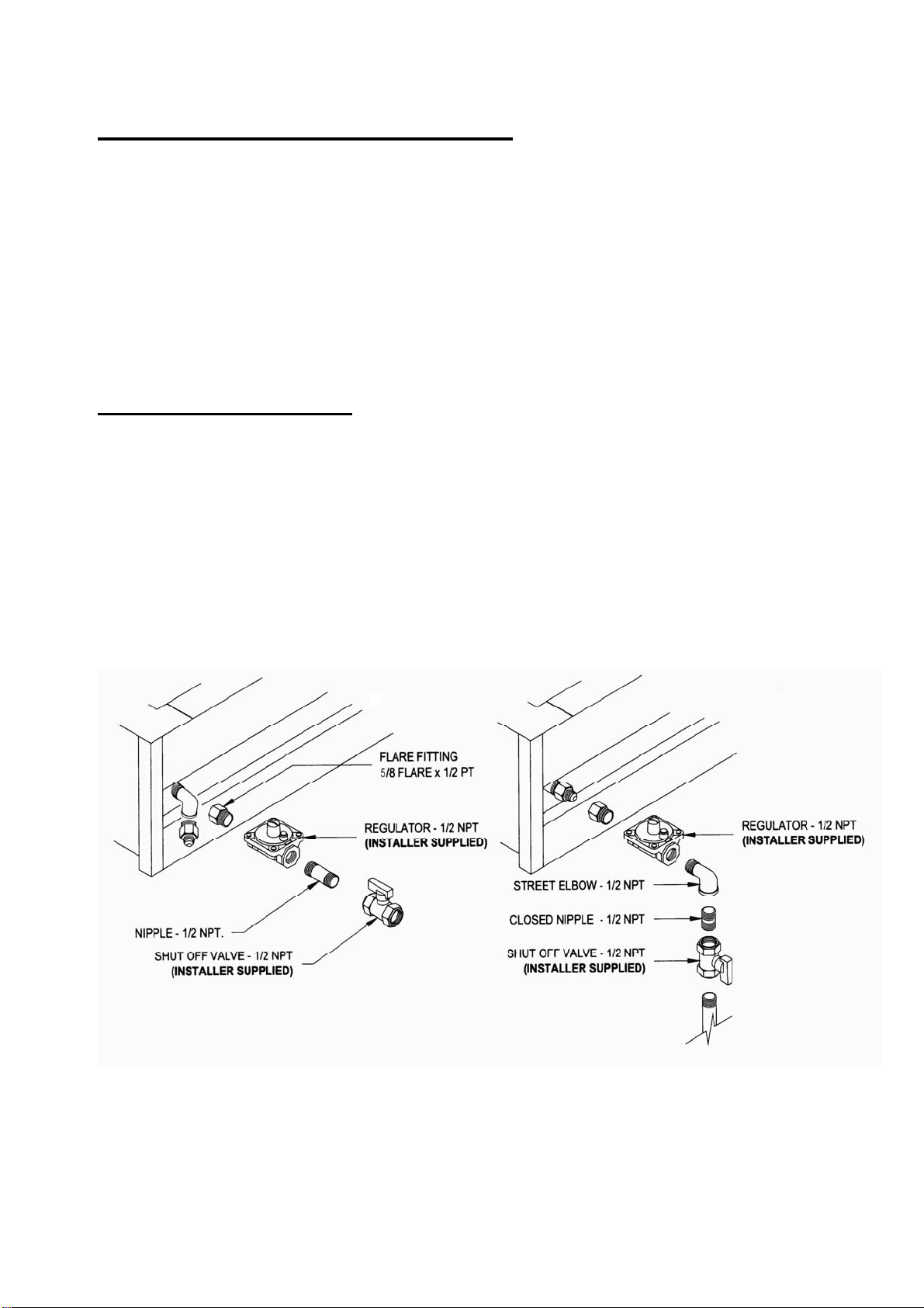
The pressure regulator and hose assembly supplied with the outdoor cooking gas appliance
must be used. Replacement of pressure regulators and hose assemblies can be
purchased from authorized dealers.
The cylinder supply system must be arranged for vapor withdrawal. Make sure the LP
cylinder has a collar to protect the cylinder valve.
(a) Do not store a spare LP gas cylinder under on near this appliance.
(b) Never fill the cylinder beyond 80 percent full.
(c) If the information in (a) and (b) are not strictly followed, a death-causing fire or
serious injury may occur.
9

Installation Location For All Models
Choose a location where the flow of air on the front of the grill is not obstructed.
Due to high temperatures, place the grill out of traffic and keep away from clothing,
furniture, etc. Keep the gas line connection as short as possible. Do not install in
recreational vehicles/mobile homes, trailers, boats, etc.
Clearances
Combustible Construction
Minimum horizontal clearance from sides and back of the unit to adjacent vertical
combustible
construction extending above top of unit, 6 inches from side and 15 inches from back.
Do not locate under overhead unprotected combustible construction.
Non-Combustible Construction
Sides of the grill can be 0” from non-combustible wall, below the cooking surface.
Built-in Installation
For non-combustible masonry enclosure installation, follow the cut out dimensions as
shown.
10

Model Size “A” Dim “B” Dim
27” 29-1/4” 17-3/8”
30” 32-7/8” 20”
36” 38-1/2” 18
42-46 45” 20”
The bottom of the grill must be supported on both sides and back or full width with
opening as shown for gas connection.
Electrical
Electrical outlet for Rotisserie motor must be installed to the left side of the grill.
The outdoor cooking gas appliance, when installed, must be electrically grounded in
11

accordance with local codes or, in the absence of local codes, with the National
Electrical Code, ANSI/NFPA 70, or the Canadian Electrical Code, CSA C22.1.
Keep any electrical supply cord and fuel supply hose away from any heated surface.
HALOGEN LIGHT: The grill is provided with a three-prong grounding plug for your
protection against shock hazard. Connect 115V power to the grill with a grounded
cord.
BRIQUETTES: Place 20 briquettes on each burner shield with 5 on each row equally
spaced front to back.
Radiant burner covers may be utilized in this model
Leak Testing
All gas piping and connections must be tested for leaks after installation or service. All
leaks must be corrected immediately.
Open the valve (shut-off or ‘ON’ LP tank). Test for leaks by applying liquid soap solution to
alljoints. Bubbles forming indicate gas leak.
NEVER USE AN OPEN FLAME TO CHECK FOR LEAKS.
12

Burner Adjustments
Every grill is thoroughly checked for proper lighting and burner flame pattern. Conditions at
the location may necessitate minor adjustment of the burner air intake, if the flames
are not steady/stable as shown in the figure.
The flame should be full length of the burner, blue and stable. The air intake should be
adjusted ONLY if the flame is lifting off of the ports or has yellow tipping.
If flame is lifting, turn the air shutter clockwise reducing this intake. The screw should
be loosened before turning the air shutter.
13

If the flame has yellow tipping, the air shutter should be turned counter clockwise allowing
more air in. This will stabilize the flame. Make sure to tighten the screw after adjustments are
made. Remove the front panel as shown (Page 17) in the diagram to access the burner
front (air shutter).
In order to provide gas to the burner, the orifice must be inside the burner venture
opening. Check to ensure that the burner is properly secured at the front and back.
Lighting Instructions
Before Lighting:
Check gas line/hose for signs of wear, abrasion or cuts. If evidence of
deterioration is
visible, replace the part prior to use.
If you smell gas, check for leaks. If odor continues, immediately call for service.
Keep your face and body away from the grill top when lighting.
Grill and Rotisserie Burner Lighting
1. Open lid before lighting. Make sure all burners are in the
‘OFF’ position.
2. Push and turn burner knob to ‘HI/IGN’ position.
3. Turn stowly allow gas to fill burner.
4. Continue step 3 untill you have burner ignition.
Operation
DO NOT LEAVE YOUR GRILL UNATTENDED WHILE IN OPERATION.
Grill: Grill burners are controlled individually with a control knob. After lighting, turn the
knob to HI, LO or in between as desired. Turn on as many burners as required. The
top cover may be closed during grilling. Keep the top cover in closed position during
the pre heat period.
Rotisserie: Turn the control knobs to HI.
14

Plug in the motor power cord to a properly grounded receptacle.
Rotisserie cooking can be done with grill burners as well as with the
Rotisserie burner ‘ON’.
The skewer slides in from the side with the tip sliding into the motor shaft
adapter. The slot on the handle side should be on the side support
panel edge.
Use the prongs to hold the meat. Tighten thumbscrew on the prong hubs to
secure in place.
When ready, turn the switch on the motor box to the ‘NO’ position. The
skewer will rotate slowly.
Stop the motor before removing the skewer.
Cleaning and Maintenance
Cleaning: Your Bar-B-Q grill works better and lasts longer if properly cleaned and
maintained. Clean the grill immediately after every use. Turn grill off before starting to clean.
Protect your hand with a good mitt when cleaning the hot grill. Use a wire brush, dip in
water and scrub the grill to soften and loosen food spills. The food spills will fall into the
crumb pan.
Do not use Aerosol cleaners on hot grill surface. Chemicals may produce
noxious fumes and may ignite on contact with the hot surface.
Shield: Burner shields (Briquette holder) are made up of stainless steel. After
every use, allow the shields to cool down. Remove and soak in water with a mild soap
or detergent. Replace when dry along with the briquettes.
Crumb Tray / Grease Pan:
Empty grease pan as required to prevent overflowing. After use, remove
the full width crumb pan and brush off the contents. Clean with hot water
and soap or detergent.
All stainless steel parts should be cleaned with a mild soap or detergent or with a liquid
cleanser especially made for stainless steel. Never attempt to clean stainless steel
with steel wool, abrasive clothes or powders.
Maintenance
Keep outdoor cooking gas appliance area clear and free from combustible materials,
gasoline and other flammable vapors and liquids.
15

Do not obstruct the flow of combustion and air ventilation.
Keep the ventilation opening(s) of the cylinder enclosure free and clear from debris.
Visually check burner flames.
There are many different stainless steel cleaners available. Always use the mildest
cleaning procedure first, scrubbing in the direction of the grain. To touch up noticeable
scratches in the stainless steel, sand very lightly with dry 100 grit emery paper in the
direction of the grain.
Specks of grease can gather on the surfaces of the stainless steel and bake on to the
surface and give the appearance of rust. For removal use, an abrasive pad (Scotch
Brite is good) in conjunction with a stainless steel cleaner. Always rub in the direction of
the grain. Never scrub the stainless steel with steel wool. Steel particles left on the
stainless steel will soon rest and give the appearance that the parts are rusting.
The burners, control area, crumb pan, etc. should be kept clean at all times. During
prolonged non-use of the grill, spiders and insects can nest in areas that will adversely
affect the functioning of the grill. Check burner inlets, orifice hood (gas inlet to burner),
igniter, sparkers, etc. thoroughly and clean before use.
16

Front Panel Removal For All Models
Parts Removal and Replacement
Grill Burner: - Remove top grates.
- Remove briquettes and shields
- Unscrew the burner at rear and slide out.
- Clean and replace in reverse order.
Grill Sparker: - Remove top grates, briquettes and shields.
- Unscrew the sparker bracket from inside.
- Disconnect wire.
- Replace in the reverse order.
Rotisserie Sparker: - Remove sparker cover – lift and pull.
- Remove sparker screws and pull out.
- Disconnect wire at rear.
- Replace in reverse order.
Switch: - Remove front panel.
- Disconnect wire from switch at rear.
- Press and push switch from rear of the panel
- Replace in reverse order.
17

Trouble Shooting
Problem Solution
Burner will not light - Check gas supply to burner by manually
lightingtheburners.
- See electrode for visible damage, replace if damaged.
Improper burner flame - Check burner gas inlet area for any blockage and
clear.
- Check orifice hoods for any clogging and clean.
- Adjust air shutter, if necessary.
- Check pressure if flame is too low or too high.
- Check gas supply tank (LP) if running low.
Light is not ON - Connect 115V power at rear. Turn switch ON.
- Check bulb. Replace if necessary.
18

19

Parts List
************
Please see your local dealer for
service and parts replacement
ITEM PART # DESCRIPTION
SM001P TOP GRATE -LARGE
01 SM002P TOP GRATE-SMALL
02 SM004P BRIQUETTES(OPTIONAL)
03 SM005P BURNER SHIELD
SM006P “U” BURNER
04 SM007P CAST BURNER
05 SM008P IGNITOR (“I.R.” BURNER)
06 SM009P WIRE (“I.R.” BURNER)
SM001F 27” & 36”-I.R. BURNER
07 SM002F 30” & 42”-I.R. BURNER
SM003F 27”-REAR HOOD
SM004F 30”-REAR HOOD
SM005F 36”-REAR HOOD
08
SM006F 42”-REAR HOOD
SM007F LIGHT BOX-RIGHT
09 SM008F LIGHT BOX-LEFT
10 SM009F LIGHT
11 SM010P BURNER SEPARATOR
12 SM010F TRANSFORMER 12V
SM011F 27”-CRUMB TRAY
SM012F 30” -CRUMB TRAY
SM013F 36” -CRUMB TRAY
13
SM014F 42” -CRUMB TRAY
SM015F 27”-GREASE TRAY
SM016F 30” -GREASE TRAY
SM017F 36” -GREASE TRAY
14
SM018F 42” -GREASE TRAY
15 SM019F FRONT FRAME BAR
16 SM020P FLARE CONNECTOR FITTING
SM021F 27”-MANIFOLD PIPE
SM023F 30” -MANIFOLD PIPE
SM024F 36” -MANIFOLD PIPE
17
SM025F 42” -MANIFOLD PIPE
18 SM026F HEAT ISOLATOR
19 SM011P GAS VALVE-I.R. BURNER
20 SM012P FLEX TUBE-I.R. BURNER
21 SM013P ORIFICE ELBOW
SM014P ORIFICE (NAT#51)-I.R. (27”&36”)
SM015P ORIFICE (LP #59)-I.R. (27”&36”)
SM016P ORIFICE (NAT#53)-I.R. (30”&42”)
22
SM017P ORIFICE (LP #56)-I.R. (30”&42”)
23 SM018P CONTROL KNOB
24 SM019P BEVZEL
25 SN020P GAS VALVE- BURNER
SM021P ORIFICE (NAT#49)-“U” BURNER(27”&36”)
SM022P ORIFICE (LP #57)-“U” BURNER(27”&36)
SM023P ORIFICE (NAT#49)-“U” BURNER(30”&42”)
SM024P ORIFICE (LP #55)-“U” BURNER(30”&42”)
SM025P ORIFICE (NAT#48)-“CAST” BURNER(30”&42”)
26
SM026P ORIFICE (LP #55)-“CAST” BURNER(30”&42”)
27 SM027P LIGHT SWITCH - ON/OFF
ITEM PART # DESCRIPTION
SM027F 27”-CONTROL PANEL
SM028F 30”-CONTROL PANEL
SM029F 36”-CONTROL PANEL
28
SM030F 42”-CONTROL PANEL
29 SM028P BRACKET-MOTOR
30 SM029P MOTOR-ROTISSERIE
SM030P 27”-WARMING RACK
SM031P 30”-WARMING RACK
SM032P 36”-WARMING RACK
31
SM033P 42”-WARMING RACK
32 SM034P HANDLE-ROTISSERIE
SM035P 27”-SKEWER ROD-ROTISSERIE
SM036P 30”-SKEWER ROD-ROTISSERIE
SM037P 36”-SKEWER ROD-ROTISSERIE
33
SM038P 42”-SKEWER ROD-ROTISSERIE
34 SM039P SKEWER FORK
35 SM031F TEMPERATURE GAUGE
SM032F 27”-HOOD HANDLE
SM033F 30”-HOOD HANDLE
SM034F 36”-HOOD HANDLE
36
SM035F 42”-HOOD HANDLE
37 SM036F BRACKET-HANDLE
38 SM037F SPACER-HANDLE
SM038F 28”-TOP HOOD
SM039F 30”-TOP HOOD
SM040F 36”-TOP HOOD
39
SM041F 42”-TOP HOOD
20
This manual suits for next models
2
Table of contents
Popular Grill manuals by other brands

George Foreman
George Foreman SUBMERSIBLE GRES060BZ use and care manual

Rohnson
Rohnson R-256 instruction manual

Weber
Weber Summit 56204 owner's guide

Miele
Miele CS1312BG Operating and installation instructions

BLUE EMBER GRILLS
BLUE EMBER GRILLS FG50069 Assembly manual and use and care

Coleman
Coleman Gas Barbecue installation manual

ROYAL GOURMET
ROYAL GOURMET CC1830S owner's manual

Gardenline
Gardenline 63187 User manual and assembly instructions

Wooshka
Wooshka SCCS001 user guide

Maxi-matic
Maxi-matic EliteGourment EGL-3450 instruction manual

Silvercrest
Silvercrest SKG 1000 B2 operating instructions

Weber
Weber GENESIS II E-310 user manual