Sun Chiro Table Prestige User manual

1
Drop Table Assembly Instrucons for the Following Lines:
Presge, Standard, Specialty
& Pracce Specials
1. Warranty, Return Policy & Table Maintenance
2. Table Assembly Instrucons
3. Trouble Shoong
CONTACT INFORMATION:
Website: sunchirotable.com
Phone: (863) 414-2893
Email: [email protected]
Our Facility:
Sun Chiro Table
4226 Commercial Dr
Sebring, FL 33870
Facility Hours:
8am to 4pm, Monday—Friday
THESE INSTRUCTIONS ARE CURRENT AS OF JANUARY 2023.
Please contact us if you have any quesons – our online customer support is always available!
Table
Maintenance
Log
Vinyl Cleaning
& Disinfecng
Guide

2
WARRANTY:
• All Standard Line Tables carry a one-year warranty on materials and workmanship (upholstery is warranted for workmanship
only).
• Presge Line and Contemporary Tables carry a two-year warranty on materials and workmanship (upholstery is warranted for
workmanship only).
• Elevaon columns installed on Contemporary tables are warranted for one year by the manufacturer of the provided columns.
• As a courtesy service we will ship replacement parts to you at no expense, however you will be responsible for the installaon
of the provided parts. The excepon to this service is tables which have been shipped outside the Connental US. In such
situaons the customer will be responsible to cover applicable shipping costs less an equivalent Domesc shipping allowance.
At Sun Chiropracc Tables, LLC sole discreon “hard parts” (dened as those mechanical table parts subject to wear and breakage)
may be provided to the original customer at no charge except for the cost of shipping, at any me both before and aer the
terminaon of the warranty periods stated above.
10 DAY RETURN POLICY:
We oer a 10 day, no-quesons asked return policy for all the standard tables we oer. Please note that this policy does NOT
include tables with custom colors or other customized opons. Tables with a custom color or other custom opons may not be
returned for any reason.
If not sased with your table for any reason you may return it at your expense for a complete refund excluding original shipping
paid. You must contact us within 10 days of arrival to let us know that you will be returning the table. This allows you 10 full days to
decide if you are happy with your purchase.
Returns will not be accepted if you fail to contact us within 10 days of the table's delivery. Tables must be returned in "new"
condion. Tables not returned in "new" condion will have their refund decreased by the stated cost of noted damage.
For the most updated warranty and return policy informaon, please see our website at sunchirotable.com.
TABLE LEVELING AND MAINTAINANCE:
Table Leveling:
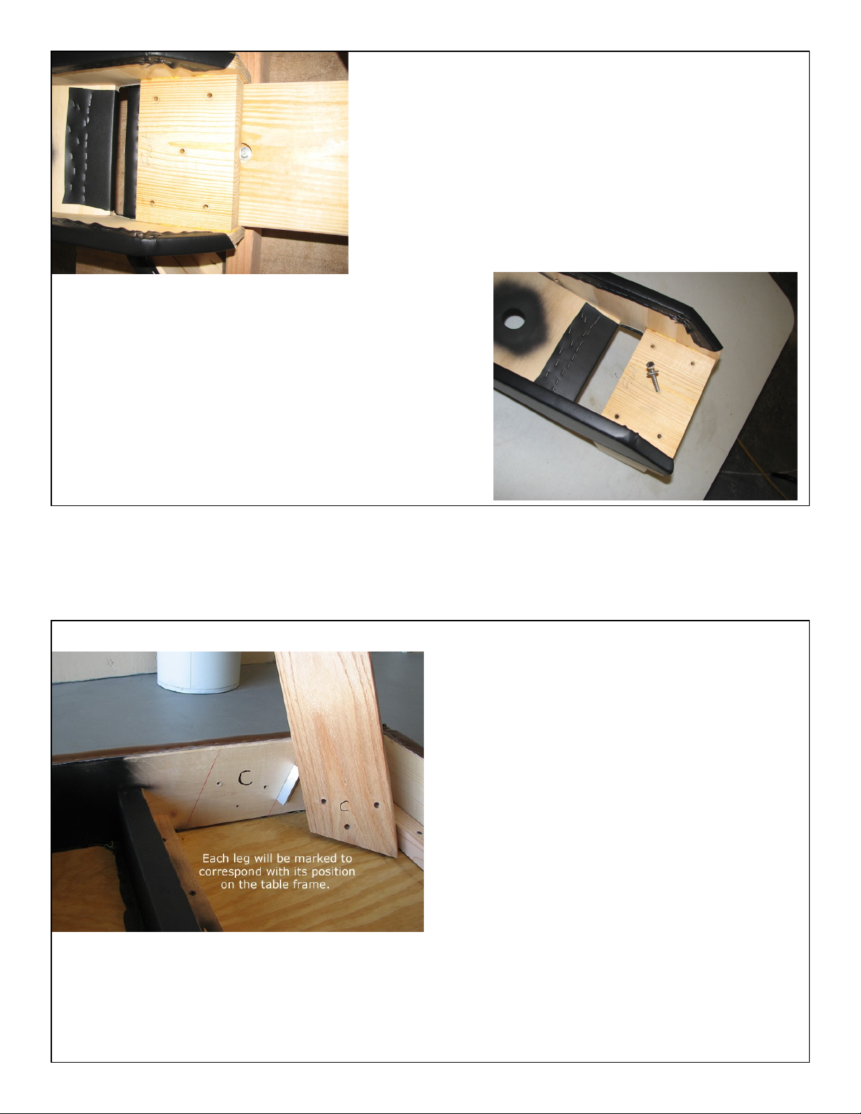
To level your table, place it in the approximate posion where it will be used. The bolt holes on the legs are oversized to
accommodate approximately 1/8” of leveling and ease assembly.
When the table is in posion, loosen the 12 leg bolts to just snug. DO NOT loosen them to the point where the washers will spin.
Place your hands on the table and “wiggle” it a bit so it can sele to the shape of your ooring. When sased, and without
moving the table, from the underside ghten the bolts to snug. DO NOT over ghten. The bolt is fully ghtened when the cut lock
washer is fully compressed and at.
Leg Maintenance:
As paents are treated the table will sele over me. This can cause the leg bolts to require ghtening. We suggest that you
ghten the leg bolts once aer about 2 weeks of use and again at about 3 months. You can then check the bolts about once every
6 months for maximum safety.
If at any me the table legs seem or appear loose, please ghten them. DO NOT wait for a scheduled maintenance period. It is a
good idea for liability purposes to keep a log of when you maintain all of your equipment.
General Maintenance:
To keep your tables in opmal condion, don’t forget to do roune table maintenance and keep a record of your inspecons. You
will nd a printable maintenance log on our website under the Customer Support > Table Documentaon tab. In the boom le
hand corner of the log there is a quick list of what should be done during the periodic inspecons. We suggest that your tables be
inspected and lubricated every 90 to 120 days for opmal performance.

3
Drop Table Assembly Instrucons for the Following Lines:
Presge, Standard, Specialty
& Pracce Specials
Geng Started:
All of our adjusng tables follow the same basic assembly instrucons described below. To as-
semble your table you will need an adjustable wrench, 1/2" wrench, 1/2" socket wrench,
7/16" socket wrench, and for handle cocking models a #2 Phillips Head screwdriver. Most of
our tables will require 20-30 minutes of your me to assemble. Some of our adjusng equip-
ment, however, requires lile or no assembly at all. Therapy Tables require leg aachment,
front triangle and lng headpiece aachment, and arm rest aachment. If you purchase our
Drop Tables you will need to aach the legs, front triangle, lng headpiece, armrests, and
drop handle or pedal. The shipping costs on our adjusng tables are kept low by shipping
them to you in this manner.
Please note that we are always here to help if you have any problems. Contact us via phone,
email or chat on our website (sunchirotable.com) at any me and we will be happy to assist
you!
Tools:
To the right you can see the tools that are helpful
in assembling our tables. You can get by with just
the adjustable wrench, however, the socket
wrenches and an extra hand wrench will considera-
bly speed the process.

4
Start by unpacking the largest box containing the table
body. Pull out all packing materials and carefully unwrap
the table from the 8 mil plastic that it is wrapped in. Our
adjusting tables are carefully packed to avoid shipping
damage. Contact us if your table shows any sign of
damage.
The plastic the table was wrapped in may be
placed on the floor to protect the table's vinyl
during the assembly process.
Now unpack the smaller box and inventory its
components. This box contains table Hardware,
Headpiece, Armrests, Triangle, and Legs. It may also
contain kick drop pedals/cocking handles and tension rod
if the purchased adjusting table has drops. Tables with
an optional foot extension will also include the foot
extension and 2 larger hairpins inside the hardware bag.
Drop Tables and Therapy Tables are shipped in 2 boxes.
The largest box contains the body of the table and the
smaller box contains the headpiece, legs, accessories,
and hardware.
Unboxing Your Table

5
Hardware Bag:
All Tables:
1. 12 Leg bolts (10 Classic Tables) consisting of 3 inch 5/16 Hex Bolts a lock washer, and a fender
washer.
2. 5 triangle bolts consisting of 3 long hex head lag screws with 1 flat washer.
3. A medium sized hair pin for the T-Bar.
4. 2 hinge pins to attach headpiece (Exception elevation headpiece equipped tables).
Elevation Headpiece Equipped Tables
1. 4 Lag screws 1 1/2 inches long and 4 flat washers in marked bag
Handle Cocking Drop Tables
1. The appropriate number of cocking handles
2. Appropriate number of tension knobs.
3. 8 #8 machine screws per cocking rod.
4. 2 cover plates per cocking rod.
Kick Drop Equipped Tables
1. The appropriate number of kick drop pedals
2. Appropriate number of tension knobs
3. 5/8 nut and lock washer for tightening the kick down rod (shipped on the rod).
Lumbar Prop and Drop Equipped Tables (marked bag)
1. Hairpin
2. Screw on handle
Arm Rests
Bag containing four 3 1/2 inch 5/16 bolts, 4 flat washers, 4 fender washers and four lock nuts.
Assembly: Step 1: Attaching the Front Triangle
This step requires the 5 triangle attachment lag
screws. These are 2 1/2 inches long and 1/4 sized.
They will be found in the hardware bag along with 5
flat washers. You will need a 7/16 socket and
wrench to easily install them.

6
With the table upside down, place the wedge over the
front of the table and pull it all the way forward.
On your table there will be a black line with two arrows
that will line up with the rear of the triangle attachment
plate.
Insert the lag screws into the holes, and using a socket
wrench, tighten them to the table (be careful not to over-
tighten).
Please note that the plate will not tighten flush with the
attachment surface. It is designed to “wedge” and will
install at a slight incline with a gap between the attach-
ment plate on the triangle and the attachment surface of
the table towards the front of the wedge. This will cause
the triangle to tip forward and transfer all of the down-
ward force put on the wedge to the table frame.
Step 2: Attaching the Legs
All adjusting tables will need their legs at-
tached. The legs are attached using twelve 3"
Bolts w/ split lock washer, flat washer and
fender washer. Each leg has a letter written
on it corresponding to its position on the table
frame.

7
Place each leg in its proper position on the
frame. The letter on the leg is placed over the
corresponding letter on the frame.
Each leg is attached using three 3" Bolts w/
split lock washer and fender washer. The
bolts are tightened with a 1/2" socket wrench.
Do NOT over tighten the leg bolts. The bolts
are fully tightened when the split lock washer
is compressed and flat.
Now, with the assistance of a helper, turn
the table upright onto its legs. You may
need to level the adjusting table at this point.
To do this, loosen all twelve leg bolts slightly
then wiggle the table a bit until it settles into
the shape of your floor. When satisfied tight-
en the leg bolts again just to snug. Do NOT
over tighten the leg bolts. The bolts are fully
tightened when the split lock washer is flat.

8
Step 3: Attaching the Headpiece
3A: Forward Drop, No Drop
We offer four different headpieces. Tables with
the standard forward drop, no drop, or the CBP
style headpiece should consult with section 3A
for assembly instructions. Doctors with the eleva-
tion headpiece with forward and toggle drop,
please consult section 3B for your instructions.
Note that the instructions for attaching the
headpiece are the same for all adjusting ta-
bles with tilt headpieces - therapy tables and
drop tables. Locate the headpiece with the T-
bar as shown.
The T-bar on the headpiece is going to be
inserted into the front hole of the triangle.
Before inserting the T-bar pull up on the tilt
release handle so that a smaller hole comes
into view.

9
This step is easier if you have a helper to pull up
on the tilt release handle while you are inserting
the T-bar.
After inserting the T-bar into the trian-
gle set the headpiece back into its
hinges and have a helper insert the
hinge pins.
The next step is to insert the hairpin into
the small hole in the bottom of the T-bar.
This pin keeps the T-bar from coming out
of the table when the headpiece is pulled
up.

10
3B: Elevation Headpiece with Forward Drop and Toggle
2014 Presge
Elevaon/Forward/Toggle Headpiece
Your new headpiece only requires a few easy steps to put the headpiece back on aer arrival.
Please follow along below and call if you have any quesons.
Step 1, is idenfy the four 1 1/2 inch long 1/4 lag screws that you will use to aach the headpiece
to the table frame. Also nd the hairpin that will go in the exion/extension t-bar. Set aside.
Step 2, take the t-bar on the boom of the headpiece and using one
hand, rotate the exion/extension handle on the side of the forward
triangle forward. This will reveal the hole in the t-bar jam.
Now take the t-bar and put it through the hole in the jam and then
let pressure o of the handle. Having a second person help is oen
makes it easy. See the picture to the right.
Step 3, let the back of the headpiece down no so that the brackets line up
with the holes in the front of the table. Using the lag screws provided aach
the brackets to the table. Do NOT ghten beyond snug at this point
Step 4, with a helper if available, lower the headpiece to neutral and stand
back to see of the headpiece is nice and level. If it is, then nish ghtening the lag screws, if not, gently
adjust the brackets ll the headpiece is level. Then ghten the lag screws.
Step 5, put the hairpin in the hole located at the boom of the T-bar you rst inserted.

11
Step 4: Attaching the Armrests
Attaching the armrests on our tables is very simple. Just match up the armrest with the correct leg
and attach using two 3 1/2" bolts w/ flat washer on outside, fender washer on inside and a 1/2 inch
nylon lock nut . A 1/2" socket wrench is required for this step with adjustable or 1/2 inch wrench.
****PLEASE NOTE*****
Your table was leveled at the factory and the arm rests installed. In the event that you had to adjust
the level of your table due to your floor, then it may be necessary to level the arm rests as well after
installation.
To do this, simply loosen the arm rest and tap up and down on it until it is parallel with the floor.
Then re-tighten the bolts. In extreme cases it might be necessary to re-drill the arm rests pilot holes.
If you feel this to be the case, please contact support at 863-202-0330 before proceeding.
Your new table for 2021 uses hex bolts to attach the arm rests rather than lag screws.
Find in your main hardware bag a smaller bag labeled arm rests.
Inside find four 5/16 Hex bolts, a flat washer, a fender washer and a nylon lock nut.
Put the flat washer on the bolt and insert it into the front hole of the arm rest and through the front leg. Thenk
add a fender washer and then the nut. Loosely tighten the nut.
Put the second bolt into the second hole of the arm rest, put on the fender washer and then they nylon lock
nut.
Tighten both lock nuts till snug but where you can still move the arm rest around a little bit.
Repeat this process on the other side of the table.
Now from the front of the table look at your arm rests and get them equal from side to side.
Then tighten the four arm rest bolts completely.

12
Step 5: Foot Extension
Foot Extensions on all 2011 tables are pre-
installed at the factory. Should you need to re-
move the foot rest, note that it consists of the ex-
tension which is attached with two hairpins as
shown to the left.
From underneath the table remove the two hair-
pins as shown to the right.

13
Now simply pull the leg extension from the
table and set aside.
Re-installation is the reverse of removal.
Also, you can use the extension without the
hairpins if you wish to be able to remove
the rest on demand.
Step 6: Attaching the Cocking Mechanism (6A Handles, 6B
Kick Drops)
Inserting the cocking rod on an adjusting table
with drops is very easy. Simply lift up the drop
cushion, place the cocking rod tip (white barrel
shaped plastic) under the drop lift arm, and
then push the cocking rod handle into the slots
of the table frame.
TABLES WITH THORACIC AND LUMBO-
PELVIC DROPS: If you have a drop table with
both Thoracic
and Lumbo-Pelvic drops each cocking rod will
be marked either "Thoracic" or "Lumbar" so
that you
know where it should be placed on the table.
6A Handles

14
Please use the following instructions to attach the
cocking handle cover plates to the side of the table.
Following the assembly
instructions for this table,
place the cocking handle
into the table slots. Be
sure that the two cover
plates for the cocking
handle are left on the
outside of the table.
When attaching the cover
plates, the widest part of
the plate should be facing
up. This ensures that the
screw holes in the cover
plates match up with the pre
-drilled holes in the side of
the table.

15
Simply attach each cover
plate using the screws
provided and a phillips-head
screwdriver.
Be sure to line up each
screw with it’s corresponding
pre-drilled hole in the table.

16
6B Kick Drops
1. You will have been provided an appropriate
number of kick drop pedals with your table. Each
pedal is attached to a down rod. That down rod
has a 5/8 inch nut on it and a single lock nut above
it. Please consult the picture to the left.
2. Take the down rod and loosely insert it into
the kick drop receiver which can be accessed
from the bottom of the table (see picture to the
right).
On tables with both thoracic and lumbar
drops, it will be necessary when installing the
second pedal to push the pedal back and
cock the drop. Then holding the pedal to the
rear you will be able to screw the down rod
into the receiver.
Now simply screw the down rod in until it is
flush with the top of the nut (see pictures to
the left.)
To make it easy you can use the pedal as a
handle to turn the rod. In some cases it may
be a bit stiff and the pedal may turn a but, but
this is OK.
Also note that you may need to jiggle the rod
a bit until it starts into the threads. If it turns
very hard, back it out and try again to avoid
cross threading the nut.
***The pedals have been designed to rest
approximately 4 inches above the floor.
This is to allow for good shoe clearance.
Should you need longer down rods, please
contact us.****

17
Finally, complete the installation by holding
the foot pedal straight out from the table
and tightening the nut and lock washer
completely.
You may find it to be easier if a helper
holds the pedal straight while you tighten
the nut.
Make sure to tighten the nut until the lock
washer is full compressed.
Please consult the picture to the left and
below.

18
Step 7: Insert the Tension Rod
The tension rod is inserted into the
hole on the table frame and then
screwed into the white drop block. Be
careful not to cross thread the hole
when screwing the rod into the drop
block (it should turn in smoothly).
Turn the rod just until you feel firm
resistance then stop.
Problem Solution
Bolt spins or won’t tighten Thread has been stripped. Call support .
Drop won’t cock after assem-
bly.
Some surface rust might have formed in shipment. Easy solution is to rap-
idly and gently move the cocking arm up and down until the drop does
cock. We then suggest spraying a very small amount of WD40 on the
plunger to lubricate it.
With time the drop seems stiff Spray the drop with a small amount of WD40.
Feel a sharp object through a
cushion
Every effort has been made to ensure that all of the cushion attachment
screws were not over driven into the cushion. Should you think that you
feel a sharp object through a cushion, look under the table at the point
where you feel the object. If you see an attachment screw, use a Phillips
head screw driver to back the screw out several turns. This should solve
the problem.
Drop won’t cock after pro-
longed use.
Spray between the lifting arm and the white block some WD 40. Then us-
ing a quick tapping method, move the cocking rod up and down until the
drop seats itself and returns to normal function.
We are always available to help! Contact us via phone, email or chat on our website
(sunchirotable.com) at any time and we will be happy to assist you!
Troubleshooting
This manual suits for next models
2
Table of contents
Other Sun Chiro Table Indoor Furnishing manuals
Popular Indoor Furnishing manuals by other brands

KayserBetten
KayserBetten Olaf Assembly instructions

Room & Board
Room & Board HOVER installation instructions

Polywood
Polywood 600 Series Assembly instructions

Simpli Home
Simpli Home brooklyn + max WyndenHall Lowry... Assembly instructions

Work Smart
Work Smart 2907 operating instructions

HAMPTON BAY
HAMPTON BAY BELCOURT MOTION D11334G-7PC2 Use and care guide