Sun-Tech SPB018 Pixel light User manual

Focus on customized architectural lighting
SPB018 Pixel light
Description
Application environment: indoor, outdoor
Measurement (Unit:mm)
The SPB018 pixel light
is a low power LED string product designed for
outdoor landscape lighting. It adopts engine
ering grade flame-
retardant
plastic PC shell, which is sealed and waterproof by high thermal conductivity
and weather
-
resistant PU glue; the lamp point is small in size and exquisite
in appearance; the light string is connected by the national standard flexible
cable, which can be bent and deformed at will, and supports the installation
of special
-
shaped façade; The product spacing and color can be
customized; it is suitable for large
-
area display or lighting of building
facades, bridges and skylights.
Features:
★
A new generation of TTL serial technology design
★
Standard DMX512 Control Protocol
★
Industry-leading wireless button-type anti-smash connection design
★
High thermal conductivity glue full potting waterproof design
★
Outdoor lightning protection and Electrostatic (ESD) special protection design
★
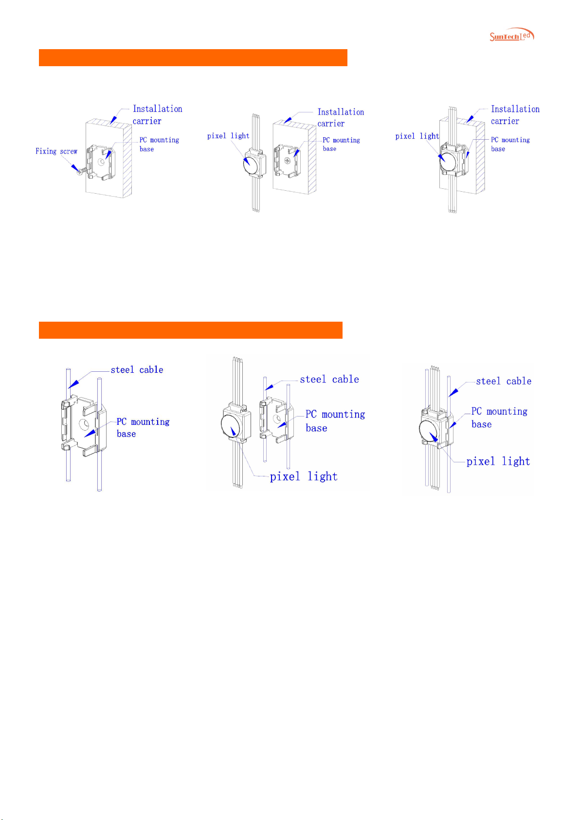
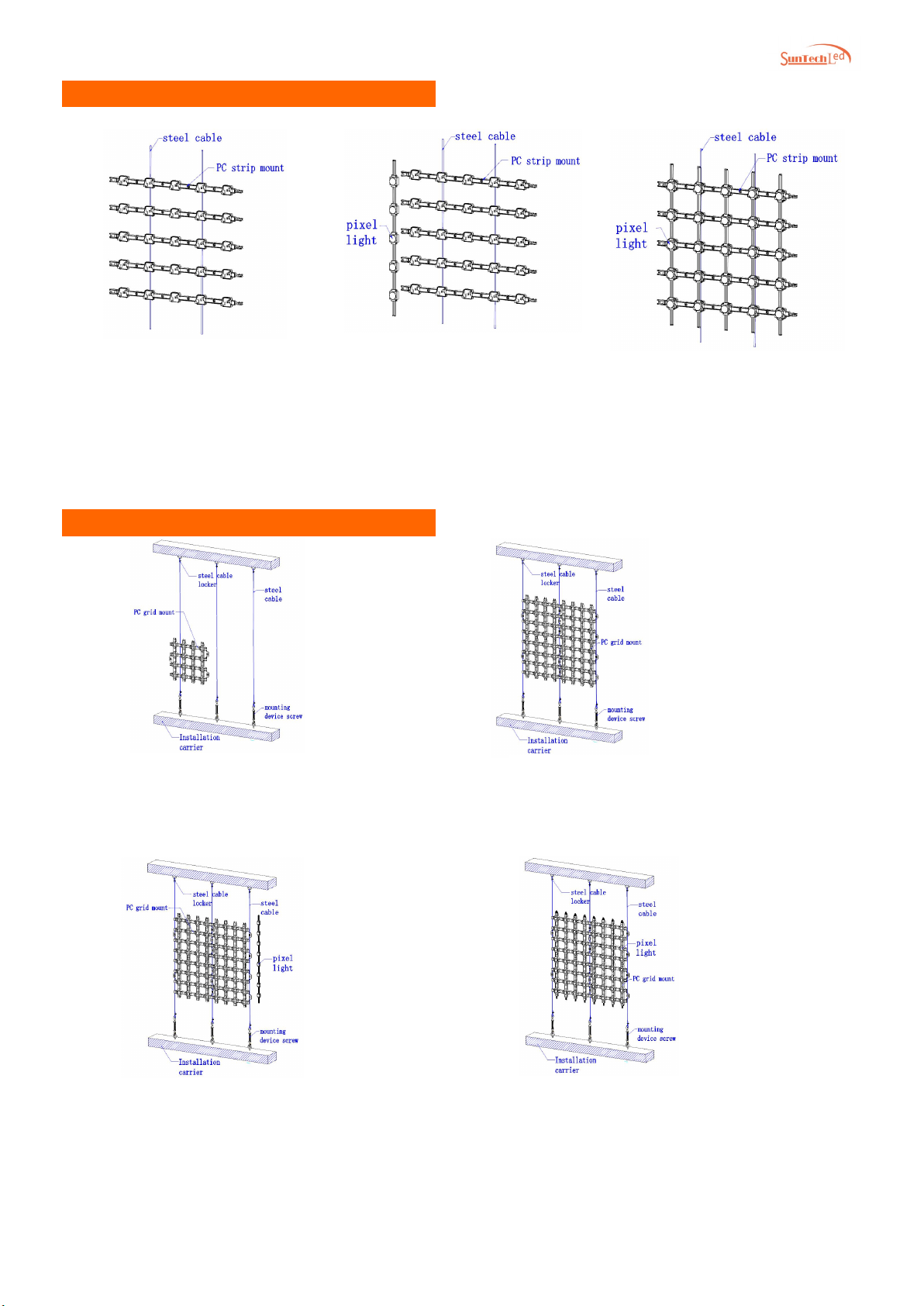
Flexible, flexible application, multiple mounting methods
★
Grid installation, strip installation transmittance of up to 94%
★
Innovative high voltage work, support longer power supply distance
★
Support RGB/W current separately adjustable (low light and high gray)
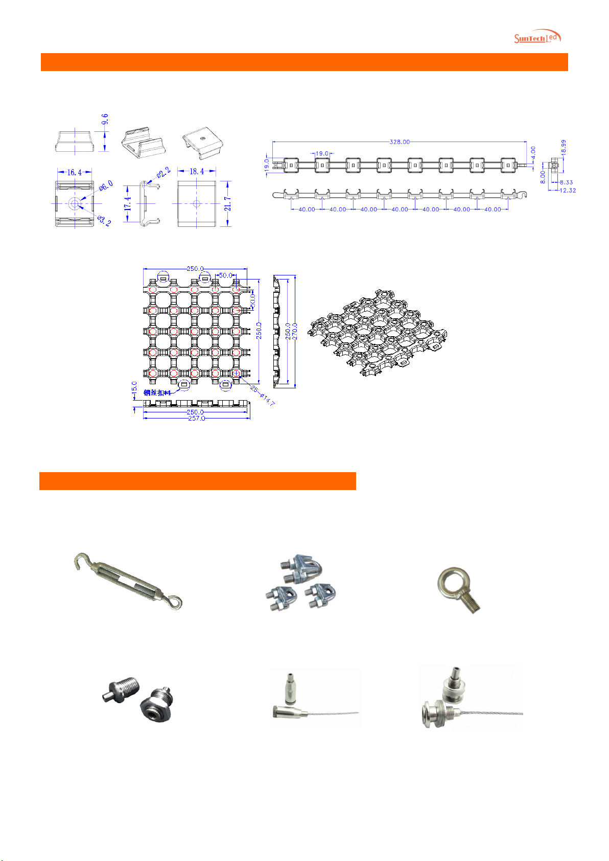
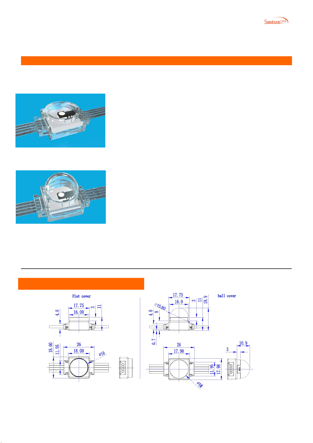
Flat cover measurement Ball cover measurement

Focus on customized architectural lighting
Technical Parameters:
Product selection table
Basic parameters
Color/gray RGB/W each 4096 grayscale;RGB/W each 256 grayscale
Light source 3535 / 5050 / 2835 LED quantities 1pcs
Material Flame retardant PC Cover material Flame retardant PC
Lifespan
50,000h
Weight
5g
Optical parameters
Operating
Voltage
DC5V / 12V
Maximum
power
0.3W / 0.5W
RGB Light
intensity
2.5cd White light 6cd
Beam angle Flat cover120°/ Ball cover 160° Electric grade Class III
Other parameters
Operating
temperature
-20°C to 50° C
Storage
temperature
-40°C to 70° C
Protection level IP66
Light distribution curve
Model
Light
source
quantities
Light
source
Color Control
DC
Operating
Voltage
Power White light
light intensity
SPB018-01AU-01 1 PCS
3535
RGB/W
Dual channel
Real-time
backup TTL
12V 0.3W 2.5cd
SPB018-01AU-02 1 PCS
3535
RGB/W
Dual channel
Real-time
backup TTL
5V 0.5W 3.5cd
SPB018-01AE-01 1 PCS 3535 RGB/W DMX512 12V 0.3W 2.5cd
SPB018-01AE-02 1 PCS
3535
RGB/W
DMX512
5V 0.3W 2.5cd
SPB018-01XT-01 1 PCS
5050
RGBW
Single line
serial TTL
5V 0.4W 4cd

Focus on customized architectural lighting
Mounting parts dimensions
Supports a single mounting piece to be fixed by screws and wire, and supports a single mounting
piece to be fixed by wire. The grid mounting piece is fixed by wire and supports profile mounting.
Commonly used wire accessories:
PC grid mount dimension drawing (unit: mm)
PC single mounting base size drawing (unit: mm)
PC strip mount dimension drawing (unit: mm)
Hanging hook
Clip head
Steel wire loop
Hanging head 1
Hang head 3
Hanging head 2

Focus on customized architectural lighting
PC single base installation method 2:
PC single base installation method 1:
②Pixel light installation:
After the PC mounting base
is fixed, the point light source
is stuck into the PC mounting
base;
③adjustment pitch :
After t
he installation is
completed, the pixel light
pitch can be fine-tuned to
ensure that the point
source is installed neatly!
(schematic diagram after
installation)
①
wire fixing and PC base
installation:
Fix the two ends of the wire to the
mounting base, and then fix the
PC mounting base to the wire.
The spacing is required according
to the order spacing of the project
order lights!
③
installation is completed:
Schematic diagram after
installation is complete.
②
pixel light installation:
After the PC mounting base is
firmly installed, the point light
source is stuck into the PC
mounting base;
①
PC installation base installation:
U
se a suitable self-
tapping screw to
secure the PC mounting base to the
desired position, with the spacing
required by the string spacing of the
project order.

Focus on customized architectural lighting
PC strip mounting method:
PC grid installation method:
①
wire and grid mounting parts installation:
Fix the two ends of the wire to the mounting
base, install the grid mounting on the wire, and
install the wire into the wire buckle.
①
wire fixing and strip mounting:
Fixing both ends of the wire on the
strip mounting module to the
mounting base
;
②
pixel light installation:
After the strip
-
shaped
mounting module is fixed,
the point light source is
stuck into the strip
-
shaped
mounting member;
③adjust the point spacing and
flatness:
After the installation is completed,
the spacing of the strip mounts
can be fine
-
tuned to ensure that
the installation is neat! (schematic
diagram after installation)
.
④Pixel light is installed:
The pixel light installation is completed,
and the system is connected.
③
installation point light source:
Take the light source light string and press the
point light source into the grid mounting piece
one by one from the back of the grid mounting
piece to the front according to the requirements
of the cloth light. Do not loosen.
②
grid mount stitching:
The grid mounting pieces are spliced one
by one and fastened and adjusted.

Focus on customized architectural lighting
Frame installation method:
②installation rubber plug:
Use a suitable rubber plug and hammer the
rubber plug into the hole drilled by the
mounting carrier; (Note: the rubber plug
should not be loose)
③mounting frame mounting base:
Align the hole of the frame mounting base
with the rubber plug hole and mount it on the
mounting carrier;
⑤
mounting profile cover:
The top cover of the profile with the point
source is installed, aligned with the
mounting base, and fastened to the profile
mo
unting base;
①installation carrier drilling:
Drill a hole in the position where the carrier
is required to be drilled by selecting a
suitable drill bit;
④
fixed frame mounting base:
After installing the frame base, lock the
mounting base with screws and do not
loosen
it;
⑥
mounting profile reinforcement
screws:
After installing the profile, use two
self-tapping screws from the lower
side to
fix the profile cover and the profile
mounting base to prevent the profile
cover from falling.

Focus on customized architectural lighting
System connection
1、The main controller is equipped with sub-controller and signal adaptor. The main control and sub-control
working voltage is AC220V. The working voltage of the signal adaptor is the same as the working voltage of
the pixel light.
2、Each sub-controller has 8 ports. The TTL sub-controller can carry 512 (RGB) pixels per port. The DMX
sub-controller can carry 170 (RGB) pixels per port. It is used with the signal adaptor and supports 200
meters long distance transmission.
3、The main control and sub-control, sub-control and sub-control are connected by CAT5 twisted cables, the
maximum distance of each section is less than 120 meters; the maximum transmission distance between
the sub-controller and the signal adaptor is less than 120 meters. In this case, the maximum distance from
the signal adaptor to the first pixel light is no more than 2 meters.
4、It is recommended that the maximum point spacing should not exceed 2.5 meters, and each intermediate
power supply can support the power supply distance of 6 meters left and right (can be adjusted according to
the project conditions).
Control system
TTL Dual channel real-time
back up
DMX512
Main controller
Sub controller MR-218A MR-218DW
Signal adaptor
Signal adaptor
AD-001Differential
Signal adaptor
AD-002Differential
Signal adaptor
Signal cable Two-core shielded wire
Two-core shielded wire,
Three-core shielded wire

Focus on customized architectural lighting
Notes:
1. Please read the installation manual carefully before using the product.
2. The product is handled gently and gently to avoid damage to the product. Installation, maintenance and
maintenance must be handled by professionals;
3. The external power supply must be cut off during wiring to prevent people from getting an electric shock or
amaging the lamp;
4. When the external power cord is connected, the corresponding measures of waterproofing and water
leakage must be taken;
5. The male and female waterproof protective covers for the products shall not be removed before the
products are installed and connected;
6. Quality Assurance: Under normal conditions of use, quality assurance is based on the proper storage,
installation, use and maintenance of the product.
(Note: Product damage caused by improper installation and use, in violation of product operating procedures, is not
within the scope of product quality assurance.)。
Table of contents
Other Sun-Tech Lighting Equipment manuals
Popular Lighting Equipment manuals by other brands

Karma
Karma STROBE 1000 instruction manual

Cover Pools
Cover Pools Save-T Cover II Installation & owner's manual

TECPRO
TECPRO Fillini user guide

HEPER
HEPER NORMA S Installation & maintenance instructions

Lightolier
Lightolier AGU specification

thomann
thomann STAIRVILLE LED Matrix Blinder 5x5 MKII user manual

CREE LIGHTING
CREE LIGHTING Cadiant quick start guide

AMP Lighting
AMP Lighting G2 AAC-HUB2-LI-SS Installation & maintenance guide

WAC Lighting
WAC Lighting dweLED FM-96916 installation instructions

Eterna
Eterna SQPRISMW installation instructions

iGuzzini
iGuzzini B183 instruction sheet

Iridium
Iridium 113778 manual