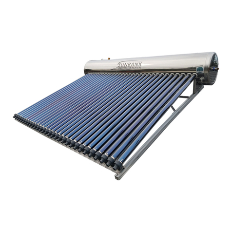
Sunbank SB-40G User manual

Quick Start Guide
SB-40G

2
Sunbank Quick Start Guide
Important points before you begin:
1. The evacuated tubes must be installed last.
The tubes quickly generate heat and need water in the tank to act as a load for the heat generated.
Keep the tubes in the box and covered until final step of installation. Do not touch copper heat pipe
without protective gloves.
2. Make sure that the heat pipes are fully inserted into the tank (about 6 inches).
First insert the condenser bulb of the heat pipe into the manifold until you feel the condenser bulb hit
against the end. Once fully inserted slide tube up to meet tank. Full instructions can be found in
section 11. Conduction paste is optional and can be found at your local hardware store.
3. Use proper freeze protection
For installations in freeze prone areas, proper freeze protection is required. Descriptions of freeze
protection can be found on our website: https://thesunbank.com/freeze-protection. If possible, design
your installation in such a way that brass fittings are not used in unconditioned spaces.
According to the SRCC, the freeze tolerance for this system is 23° F or -5° C. Freeze tolerance limits
are based upon an assumed set of environmental conditions. Extended periods of cold weather,
including ambient air temperatures above the specified limit, might cause freezing in exposed parts of
the system. It is the owner’s responsibility to protect the system in accordance with the supplier’s
instructions if the air temperature is anticipated to approach the specified freeze tolerance limit.
4. Put pipe dope on female and male threading then wrap with Teflon tape.
The threading of the Sunbank ports are such that they require at least 4 wraps of high quality Teflon
tape. To prevent leaks you should put pipe dope on the female threads and on the male threads, then
wrap Teflon tape over the male threads. This is a plumber’s trick and the best way to avoid leaks.
5. Make sure to insert the temperature sensor the full 6 inches into the thermowell.
This is only applicable to installations that are installing the optional controller and heating element.
When inserting the temperature sensor into the blue cord grip on the tank make sure it goes all the
way up (about 6 inches) into the tank. Otherwise you will get a bad reading which can cause your
system to overheat.
6. When filling the tank, release the T/P valve to ensure no air is trapped in the tank.
Once a steady stream of water is being expelled you can be satisfied that there is no trapped air.

3
Sunbank Quick Start Guide
Table of Contents
1. Included Parts ……………………………………………………………………………………… 4
2. Not Included Parts ……………………………………………………………………………………… 5
3. Project Overview ……………………………………………………………………………………… 6
4. Plumbing Diagram ……………………………………………………………………………………… 7
5. Tank Diagram ……………………………………………………………………………………… 8
6. Bracket Diagram ……………………………………………………………………………………… 8
7. Reinforce Roof ……………………………………………………………………………………… 9
8. Roof Attachments ……………………………………………………………………………………… 9
9. Insulation ……………………………………………………………………………………… 10
10. Filling the Tank ……………………………………………………………………………………… 10
11. Tube Installation ……………………………………………………………………………………… 11
12. Temp Sensor/Aux Heater ……………………………………………………………………………………… 12
13. Project Completion ……………………………………………………………………………………… 12
14. Plumbing Labels ……………………………………………………………………………………… 13
15. Operation & Maintenance ……………………………………………………………………………………… 15
17. Warranty ……………………………………………………………………………………… 16
18. Specification Sheet ……………………………………………………………………………………… 17
Notice:
The solar energy system described by this manual, when properly installed and maintained, meets the
minimum standards established by the SRCC. This certification does not imply endorsement or
warranty of this product by SRCC.
All installations should comply with building, plumbing, mechanical and fire code adopted by the
authority having jurisdiction or, in the absence of such codes, with the International Building Code,
International Plumbing Code, International Mechanical Code, and International Fire Code.
Sunbank accepts no responsibility for the misuse or improper installation of this product. This manual
is illustrative not comprehensive. It does not cover personal safety when working on a roof, for
example, or go into depth regarding structural, plumbing, or electrical work. The installer should have
the proper training and knowledge in these areas. If you do not have the proper plumbing, roofing,
and electrical experience then you should not attempt to install the Sunbank.

4
Sunbank Quick Start Guide
1. Included Parts
The basic Sunbank system includes:
1 - 40 Gallon Tank
1 - Bracket (assembly required)
15 - Evacuated tube solar collectors (including aluminum fin, stainless heat pipe, and
cap assembly)
15 - Plastic tailstocks
15 - Dust rings
1 - Magnesium Anode
1 –½” Temperature and Pressure (T/P) Valve
1 –½” Hy-Vent Air Eliminator
1 –Auxiliary Electric Heater
Stand-alone accessories:
1 –Electronic temperature controller with sensor wire and thermowell
T/P Valve
Hy-Vent
Plastic Tailstock
Dust Rings (Black or White)
Controller
Thermowell

5
Sunbank Quick Start Guide
2. Not Included Parts
The specific hardware necessary is installation and climate specific.
The Sunbank can be installed as a pre-heater with a bypass or as a standalone system. The
following parts list is for the basic pre-heater setup:
1 –roll of PEX or copper pipe (length and diameter dependent upon installation)
1 –roll of Teflon plumbing tape
1 –bottle of thread sealant
1- 4.4 gallon potable water expansion tank
2 –¾” FNPT PEX adapters to interface with tank inlet and outlet
2 –¾” FNPT caps (if not using side ports –most installations)
2 –¾” MNPT drain valves
6 –T’s (diameter depends on PEX size chosen)
6 –Ball valves (see plumbing configuration diagram in Part 4 for explanation)
1 –Flashing to interface with the roof/building penetration point
1 –lead free mixing valve (also referred to as a tempering valve)
4 - roof attachments (type depends on roof surface –contact us for suggestions)
Installation specific plumbing fittings to interface with existing plumbing
Armaflex or similar rubberized pipe insulation
Optional:
1 –3.25” x 10” x 6” register boot to interface with the tank
1 –aluminum jacketing, or 6” aluminum flexible duct for UV exposed insulation
Otherwise paint any exposed insulation for UV protection
1 –freeze protection valve More info: https://thesunbank.com/freeze-protection/
Stand-alone system, you will need an additional:
1 –Length of appropriately sized heating cable for electric element

6
Sunbank Quick Start Guide
3. Project Overview
1. Before starting an installation, it is necessary to know where you plan to mount the
Sunbank and where you plan to interface with the existing plumbing system. Once this is
clearly defined, you can purchase the necessary plumbing supplies.
2. If a permit is required in your jurisdiction contact us for more resources. We will provide
you with documents that you will need for a permit and can connect you with a structural
engineer, if necessary.
3. Assemble the Sunbank bracket and find the rafters on which you plan to mount it. Lag
flashed attachments to roof and mount bracket so that you can plan where to bring the
plumbing into the building.
4. Run the plumbing to the existing water heater, or nearest plumbing in the case of a stand-
alone installation. Make the plumbing connections according to the Sunbank plumbing
schematic.
5. Connect plumbing and fill with water (see instructions for how to fill properly in order to
take air out of system) and check for leaks. Do not insulate and jacket until you have
checked for leaks.
6. Install tubes (kept in the box until now to prevent overheating). Tighten nuts to secure
tank to the bracket
7. Enjoy free hot water, courtesy of the sun!

7
Sunbank Quick Start Guide
4. Plumbing Diagram
5. The Sunbank can be installed as a stand-alone or a pre-heat system. The following diagram
shows the pre-heat configuration. The stand-alone is the same but without the existing
domestic water heater and water heater bypass/shutoff valves. If a backflow prevention valve
is present in the system you should add an expansion tank to the plumbing configuration.
Note: Drain the T/P valve to the gutter to avoid hot water on roof material

8
Sunbank Quick Start Guide
5. Tank Diagram
6. Bracket Diagram
Bracket can be installed either as a flush mount directly onto a pitched roof, or with rear legs on a flat
roof as shown below. The flat roof bracket angle can be adjusted by cutting the aluminum rear legs.

9
Sunbank Quick Start Guide
7. Reinforce Roof
Whether or not it is necessary to reinforce the roof depends on the existing roof structure. A structural
engineer is qualified to assess a roof and to prescribe reinforcement measures that must be performed
before installation. Send us an email for general guidance regarding weight tolerances based on roof
structure as well as structural engineering referrals.
8. Roof Attachments
Roof attachments are specific to the type of roofing to which you are attaching the Sunbank. For
mounting to most composition shingle roofs, we recommend a flashed L foot design like the Snap-N-
Rack Series 100 (pictured below) or a Quickmount QBase. Quickmount also makes attachments for
tile roofs. S-5! makes metal roof attachments. More information and installation diagrams can be
found on their websites:
www.snapnrack.com
www.quickmountpv.com
www.s-5.com

10
Sunbank Quick Start Guide
9. Insulation
All plumbing that is exposed to the elements should be adequately insulated and jacketed; how best
to do this will depend on the specifics of your installation and your climate. Below are examples of
insulation and jacketing systems. Aluminum jacketing for solar thermal projects can be found here:
http://www.buyinsulationproductstore.com. We have found that 6” aluminum flex duct and aluminum stack
vent are the products most commonly available at hardware stores and serve the same function.
A register boot will interface with the tank. You can use rivets or tek screws to connect the boot to the
tank and butyl tape to flash. Remember, don’t do this until you have filled the tank with water and
checked for leaks.
10. Filling the Tank
If possible, first pressure test the system with air.
Make certain the drain valve is closed and open the T/P valve on the tank to allow air to escape. Open
the solar isolation valves to allow water to fill the Sunbank tank and immediately go to the roof to
close the T/P valve once water comes out and the tank is full. Close the solar bypass valve to force
cold water into the Sunbank. Check the tank and cold water lines for leaks and repair any found.

11
Sunbank Quick Start Guide
11. Tube Installation
Fill the tank before installing the tubes.
The last step is to install the tubes. You can also find video instructions on our Youtube page.
1. Attach the plastic tailstocks to the bottom of the bracket and unscrew the cap. Put the dust
ring around the top end of the evacuated tube about 1 inch from the top. Use mild soap and
water to ease on the dust ring.
2. Put the bottom of the evacuated tube through the plastic tailstock and pull the heat pipe out of
the tube about six inches.
3. Guide the condenser bulb of the heat pipe into the manifold until it can’t be pushed any
further. Rotate the tube if there is resistance. It should fit easily.
4. Slide the tube so that it fits up against the tank. Maintaining upward pressure on the tube,
screw the cap of the tailstock on to hold the tube in place. It should screw easily—be sure
that you have the threading lined up.
5. Adjust the dust ring so that it fits snugly between the tank and the tube.
6. Repeat.

12
Sunbank Quick Start Guide
12. Temperature Sensor/Auxiliary Heater
While you are putting teflon tape on the temperature sensor thermowell you will notice that it extends
6 inches or so up into the tank. When you are installing the actual temperature sensor wire it is
important that it goes all the way to the end of this well. This ensures an accurate reading.
The temperature sensor wire is 150 feet long and it should be run in conduit protected from UV.
The controller comes with its own manual that will explain wiring, settings, and various functions.
13. Project Completion
Once the tubes are installed the system should be ready for use. Again, make sure that there are no
leaks at the fittings and that the insulation is sufficient and sealed appropriately.
The next time you should need to think about your Sunbank is to check and change the magnesium
anode. Like any water heater, this anode should be changed in order to keep the inner tank from
corroding. The frequency with which you should change this anode depends on the total dissolved
solids (TDS) of your local water supply. If you don’t have a good idea of your local TDS, Sunbank
recommends that you check the anode three years from installation and base future checks on the
amount of the existing magnesium anode that is left at this point.
Addendum:
Installing heat tape
If installing heat tape, be sure that the heat tape thermostat is experiencing the same conditions as
the PEX tubing. It should be wrapped with the tubing and well insulated so that it avoids turning on
too much by being overexposed, or too little which could result in freezing.
Stand-alone setup
If you are using the Sunbank as a stand-alone system, you will also be using the auxiliary electrical
heater and controller. The temperature sensor and heating element should be installed prior to filling
the tank with water and the wiring should be jacketed.

13
Sunbank Quick Start Guide
14. Plumbing Labels
COLD Line
HOT from Sunbank
If an issue arises, please call your
local installer:
____________________________
(phone #) ____________________

14
Sunbank Quick Start Guide

15
Sunbank Quick Start Guide
15. Operation & Maintenance
Once the Sunbank is installed, the tank filled, and the valves turned according to the diagrams above,
your Sunbank is operational. Because your system is now pressurized via municipal or well water
pressure, the Sunbank delivers hot water by simply opening your hot water faucets.
Magnesium anode
Every Sunbank comes with a magnesium anode meant to protect the inner tank from corrosion. How
fast this sacrificial anode will corrode depends on your local water quality. We recommend that you
check the anode one year after installation and base future replacements on how much of the anode
remains. You can buy replacement anodes from Sunbank or your local hardware store.
Draining the Tank
In order to drain the water heater, close V2 and V3. Attach a garden hose to the drain valve and direct the
hose to a drain. Open V4 and V5.
Vacation Mode
If you are going to be away from home for an extended period you might consider deactivating the
system so that it does not continue to heat the water tank while hot water is not being used.
To deactivate the system:
1. Unplug or otherwise turn off the heating element via the Sunbank controller.
2. Remove or cover the collectors (or rotate them so that the opaque painted side is up, if you have
painted them)
When you return, simply reverse the procedures to reactivate the system.
If the collectors are likely to be covered with snow for an extended time, or if the system will not be
used for one month or longer in a place that experiences freezing conditions, the water heater and
piping should be drained to prevent freezing or stagnant water. Make certain the water heater is
completely filled again before placing it in operation.
Maintenance
There is relatively little required maintenance for the Sunbank. Properly maintained, your solar water
heater system will provide years of dependable trouble-free service.
The evacuated tube collectors should last for 15 years without significant degradation. The tank life
depends on the local water quality and how frequently the magnesium anode is changed. Stainless
steel tanks are the most durable and expensive tanks to produce, but if not properly maintained in
areas with hard water they can corrode which will shorten their working life.

16
Sunbank Quick Start Guide
16. Warranty
Sunbank offers a 10 year limited warranty on the collectors, a 5 year limited warranty on the tank, and a
1 year limited warranty on all other components of the system.
Warranty claims made on products with a manufacturer’s defect will be honored. Damage that occurs
during or due to a faulty installation is not covered under the warranty. Nor does it include damage from
anything outside of Sunbank’s control, such as an act of nature or Force Majeure. Sunbank will replace
defective parts at no charge but will not pay for or provide the labor to replace those parts.
In order to obtain warranty coverage, the customer should send a description of the problem with
photos to support the claim to info@thesunbank.com. Proof of purchase, such as an invoice marked
‘PAID’ from Sunbank, is required as we do not warranty any products that were not sold by Sunbank or
one of our dealers, distributors, or installers.

17
Sunbank Quick Start Guide
Other manuals for SB-40G
2
Table of contents
Other Sunbank Water Heater manuals
Popular Water Heater manuals by other brands

ACV
ACV Smartline Multi Energy 210 Installation, operating and servicing instructions

Danfoss
Danfoss TERMIX PM2+P installation guide

A.O. Smith
A.O. Smith ATI-305-N Selection guide

clage
clage CEX-U ELECTRONIC MPS Installing instructions

enertik
enertik BC-F20HWR2-200L Installation and user manual

Grainfather
Grainfather EZZZ9169 instructions

Maytag
Maytag HJ640NOVET user guide

Lochinvar
Lochinvar Copper-Fin 2067 Installation & service manual

OSO
OSO Wallsmart W 30 User manual and spare parts list

Giant Factories
Giant Factories ANSI Z21.10.3 owner's manual

State Water Heaters
State Water Heaters Gas Specification sheet

Lochinvar
Lochinvar Copper-Fin II CF991 Replacement parts list