SOLAREVER SE1-SPT User manual

614.00737.00
SE1-SPT
User Manual
3.0kW - 7.0kW
UL
Copyright Declaration
The copyright of this manual belongs to Solarever Tecnologia de America S.A.de C.V.. Any
corporation or individual should not plagiarize, partially or fully copy (including software, etc.), and
no reproduction or distribution of it in any form or by any means. All rights reserved. Solarever
Tecnologia de America S.A.de C.V. reserves the right of nal interpretation. The contents are subject
to change without prior notice.
www.solarever.com.mx
Solarever Tecnologia de America S.A.de C.V.
Autopista Mexico-Queretaro KM 71.9, S/N Noxtongo
Tepeji del Rio de Ocampo C.P. 42885, Hidalgo Mexico
Email: contacto@solarever.com.mx
Web:www.solarever.com.mx

01
Contents
03
03
03
04
10
12
13
13
16
18
19
21
21
22
22
23
24
24
26
27
29
32
29
29
30
2.1 Basic Feature
2.2 System Diagram
2.3 Work Modes
2.4 Dimension
2.5 Terminals of Inverter
3.1 Input PV
3.2 Output/Input AC
3.3 Battery
3.4 Load output (with battery)
3.5 Efficiency, standard, environment limit and others...
4.5.1 Installation Carrier Requirements
4.5.2 Installation Requirements
4.5.3 Installation Space Requirements
1.1 Scope of Validity
1.2 Target Group
1.3 Symbols Used
1.3.1 Important Safety Instructions
1.3.2 Explanation of Symbols
1.3.3 CE Directives
4.1 Check for Transport Damage
4.2 Packing List
4.3 Installation Precautions
4.4 Tool Preparation
4.5 Installation Site Conditions
4.6 Mounting
1 Note on this Manual
2 Introduction
3 Technical Data
4 Installation
03
13
21
24
...................................................................
.......................................................
...................................................................
.........................................................................................
...................................................................................
...........................................................................................
.........................................................................................
............................................................................................
....................................................................................
...............................................................................................
...................................................................................................
..........................................................................
...........................................................................................
.......................................................................................................
...................................................................................
............................................................................................................
.............................................................
....................................................................................
......................................................
...............................................................................................
...................................................................
.....................................................................................
..........................................................
..............................................
.............................................................
...............................................
............................................................................................
.....................................................................................................
03
02
1 Notes on this Manual
1.2 Target Group
This manual is for qualied electricians. The tasks described in this
manual only can be performed by qualied electricians.
1.3 Symbols Used
Danger!
“Danger” refers to a dangerous situation that, if not
avoided, will result in a high level of risk such as serious
injury or even death.
Warning!
“Warning” indicates a hazardous situation which, if not
avoided, could result in serious injury or death.
Caution!
“Caution” indicates a hazardous situation which, if not
avoided, could result in minor or moderate injury.
1.1 Scope of Validity
SE1-SPT-3K SE1-SPT-6K
SE1-SPT-3.6K SE1-SPT-7K
Note: ”SE1-SPT Series refers to the energy storage inverter
that supports photovoltaic grid-connected.
“3k"means 3.0kW.
Keep this manual available at any time.
5 Electrical Connections...........................................................36
.........................................................................................
5.2 Grid Port and load Output Connection................................
..............................................................................5.3 Battery Connection
5.4 Communication Connection.......................................................
5.4.1 Introduction to C T Communication.........................................
5.4.2 COM Communication......................................................................
5.4.3 Communication Connection Steps...........................................
5.5 Grounding (Mandatory)....................................................................
5.6 Monitoring Connection....................................................................
5.7 Check All Below Steps Before Starting Inverter..............
5.8 Inverter Operation.................................................................................
6 Firmware upgrading..........................................................................................68
7 LED Indicator..................................................................70
8 Troubleshooting....................................................... 71
8.1 Trouble Shooting............................................................ 71
............................................................. 79
9 Decommissioning 80
10 Disclaimer 81
11 APP User Guide
* Warranty registration form
5.1 PV Connection
36
41
48
51
51
54
56
61
64
66
67
80
80
80
80
9.1 Disassemble the Inverter
9.2 Packaging
9.3 Storage and Transportation
9.4 Waste Disposal
...............................................................
...................................................................................................
.. .........................................................
........................................................................................
....................................................................
........................................................................................
The following types of safety instructions and general information
appear in this document as described below:
Notice!
“Notice” provides tips that are valuable for the optimal
operation of our product.
This manual is an integral part of SE1-SPT, It describes the
assembly, installation, commissioning, maintenance and failure of
the product. Please read it carefully before operating.
8.2 Routine Maintenance
82
........................................................................................
Caution!
When the inverter is working, it is strictly forbidden to touch the
shell. The temperature of the shell can is high and there is a risk
of scalding.
Caution!
Radiation may be harmful to health!
Do not stay for a long time and keep at least 20 cm away from
the inverter.
Notice!
Ground PV system.
Finish PV modules and photovoltaic system grounding in
accordance with local requirements to achieve optimal
protection of systems and personnel.
Warning!
Ensure that the input DC voltage is below the inverter limit.
Excessive DC voltage and current may cause permanent
damage or other losses to the inverter, which is not covered by
the warranty.
Warning!
Authorized service personnel must disconnect the AC and
DC power supply of the inverter before performing any
maintenance, cleaning or operation of any circuit
connected to the inverter.
Warning!
Risk of electric shock!
Warning!
The inverter can not be operated when it is running.
Strictly follow relevant safety specifications for product installation
and testing. During installation, operation or maintenance, please
read carefully and follow the instructions and precautions on the
inverter or user manual. If the operation is incorrect, it may cause
personal and property losses. Please keep the user manual properly
after use.
This inverter can only use the accessories sold and recommended by
Solarever, otherwise it may cause fire, electric shock or casualties.
Without the authorization of our company, you may not open the
inverter cover or replace the inverter parts, otherwise the warranty
promise of the inverter will be invalid.
The use and operation of the inverter must be carried out in
accordance with the instructions in this manual, otherwise this
protection will fail and the warranty of the inverter will also fail.
During working, the inverter surface temperature may exceed 60 , °C
please make sure the inverter cools down before touching, and
make sure children can not touch.
When exposed to sunlight, photovoltaic arrays generate dangerous
high DC voltages. Please follow our instructions, otherwise it will be
life-threatening.
All DC and AC power sources must be disconnected from the
inverter for at least 5 minutes before any wiring or electrical
operation is performed on the inverter to ensure complete isolation
of the inverter and avoid electric shock.
05
04
Safety
Danger!
Danger to life due to high voltages in the inverter!
The personnel responsible for the installation, electrical
connection, debugging, maintenance and fault handling
operation of this product need to be trained, master the correct
operation method, have the corresponding electrician
qualification and safety operation knowledge.

If the building installed with external light protection device is far
away from the inverter location, in order to protect the inverter from
electrical and mechanical damage, the inverter should also install an
external lightning protection equipment.
In order to protect DC system, two-stage surge protection equipment
is needed between DC cable of inverter and photovoltaic equipment
module.
In order to protect the AC system, the level 2 surge protection
equipment should be installed at the AC output, located between
the inverter and the grid. Installation requirements must comply with
IEC61643-21 standard.
All DC cables shall be installed in a distance as short as possible, and
the positive and negative cables of the same input need to be
bundled together to avoid causing loops in the system. Minimum
distance installation and binding requirements also apply to auxiliary
grounding and shielding grounding conductors.
07
06
Warning!
ØSurge protection devices (SPDs) for PV installation
Safety
A photovoltaic module used on the inverter must have a IEC61730A
rating, and the total open circuit voltage of the photovoltaic string /
array is lower than the maximum rated DC input voltage of the
inverter. Any damage caused by photovoltaic over voltage is not
covered by warranty.
Installation position should be away from wet environment and
corrosive substances.
After the inverter and power grid cut off the PV power supply, there
will be a certain amount of residual current in a short time, be
cautious or it may lead to serious personal injury and even high risk
of death.Use a multimeter (impedance at least 1 MΩ) to measure the
voltage between the UDC + and the UDC- to ensure that the inverter
port is discharged below the safe voltage before starting operation
(35 VDC).
Over-voltage protection with surge arresters should be
provided when the PV power system is installed.
The grid connected inverter is fitted with SPDs in both
PV input side and MAINS side.
Direct or indirect lightning strikes can cause failures. Surge is the main
cause of lightning damage to most devices. Surge voltage may occur
at photovoltaic input or AC output, especially in remote mountain
areas where long distance cable is supplied.
Please consult professionals before installing SPDs.
The external lightning protection device can reduce the inuence of
direct lightning strike, and the lightning protection device can release
surge current to the earth.
09
08
Safety
Solarever SE1-SPT Series inverter should pair with high voltage battery, for
the specic parameters such as battery type, nominal voltage and
nominal capacity etc., please refer to section 3.3.
Please refer to the matching battery specication for details.
ØBattery Safety Instructions
For United Kingdom
• The installation that connects the equipment to the supply terminals
shall comply with the requirements of BS 7671.
• Electrical installation of PV system shall comply with requirements of
BS 7671 and IEC 60364-7-712.
• All protective devices cannot be changed.
• User shall ensure that equipment is so installed, designed and
operated to maintain at all times compliance with the requirements of
ESQCR22(1)(a).
ØPE Connection and Leakage Current
• All inverter’s incorporate a certified internal Residual Current Monitoring
(RCM) in order to protect against possible electrocution and fire hazard
in case of a malfunction in the PV array, cables or inverter.
There are 2 trip thresholds for the RCM as required for certification
(IEC 62109-2:2011).
The default value for electrocution protection is 30mA, and for slow
rising current is 300mA.
The islanding effect means that when the power grid is cut off, the
grid-connected power generation system fails to detect the power
outage and still supplies power to the power grid. This is very dangerous
for the maintenance personnel and the power grid on the transmission
line.
SE1-SPT series inverters use active frequency offset method to prevent
islanding effect.
ØAnti-lslanding Effect
Warning!
High leakage Current!
Earth connection essential before connecting supply.
• A faulty ground connection can result in equipment failure, personal
and death injuries, and electromagnetic interference.
• Ensure correct according to grounding to IEC62109 and conductor
diameter according to STANDARD specification.
• Do not connect the grounding end of the equipment in series to
prevent multi-point grounding.
• Electrical appliances must be installed in accordance with the wiring
rules of each country.

10 11
Safety
1.3.2 Explanation of Symbols
Type A pprov ed
Saf ety
Regu lar Pro duct ion
Sur veil lance
www. tuv.co m
ID 111 12274 31
CE mark.
The inverter complies with the requirements of the
applicable CE guidelines.
This section gives an explanation of all the symbols shown on the inverter
and on the type label.
Battery status
UKCA mark.
The inverter complies with the requirements of the
applicable UKCA guidelines.
UKNI mark.
The inverter complies with the requirements of the
applicable UKNI guidelines.
Operating Display
An error has occurred, please inform your installer immediately
Symbols on the Type Label
Symbols on the Inverter
Symbols
TUV certified.
RCM remark.
ETL certification.
The inverter can not be disposed together with the
household waste. Disposal information can be found in the
enclosed documentation.
Do not operate this inverter until it is isolated from battery,
mains and on-site PV generation suppliers.
Danger to life due to high voltage. There is residual voltage
existing in the inverter after powering off, which needs 5 min
to discharge. Wait 5 min before you open the upper lid or
the DC lid.
Beware of hot surface.
The inverter can become hot during operation. Avoid
contact during operation.
Danger of high voltages.
Danger to life due to high voltages in the inverter!
Danger.
Risk of electric shock!
Observe enclosed documentation.

SE1-SPT series is a high-quality inverter that can convert solar energy
into alternating current and store energy into batteries.
The inverter can be used to optimize self-consumption, stored in
batteries for future use or fed into the public grid. The way it works
depends on user preferences. It can provide emergency power during
power outages.
2 Introduction
2.1 Basic Features
SE1-SPT series are designed to has Load wiring scheme,
customers can choose Load compatible parts Load compatible
with all load use.
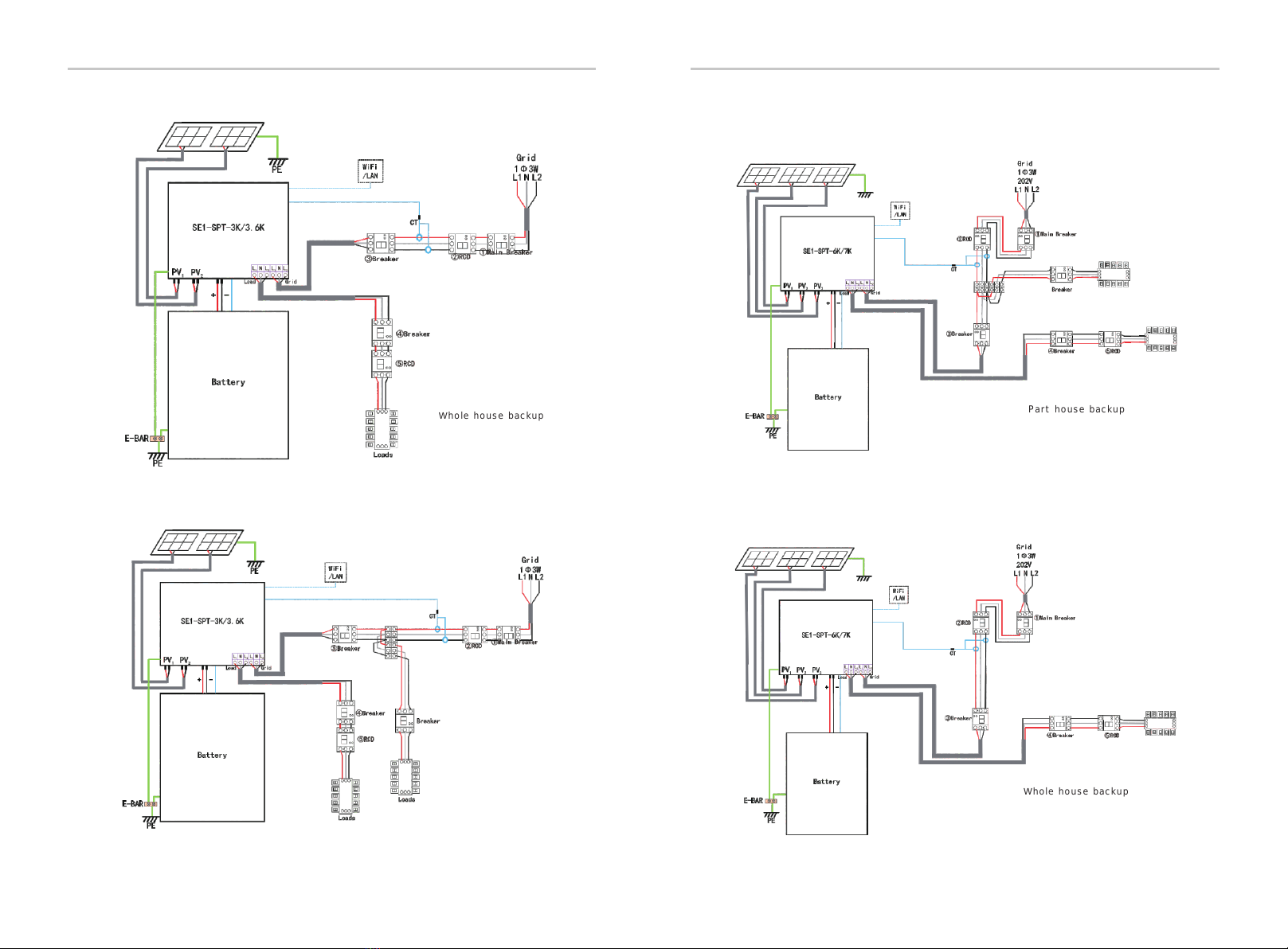
2.2 System Diagram
Diagram : Neutral line and PE line are separated from each
other, and the common load is connected to the Load port;
(For most countries)
Introduction
For installation in photovoltaic module system, it is necessary to
make sure that the whole system complies with the requirements of
EC(2014/35/EU, 2014/30/EU, etc.) before starting the module (i.e. to
start the operation). The assembly shall be installed in accordance
with the statutory wiring rules. Install and configure the system in
accordance with safety rules, including the use of specified wiring
methods. The installation of the system can only be done by
professional assemblers who are familiar with safety requirements
and EMC. The assembler shall ensure that the system complies with
the relevant national laws.
The individual subassembly of the system shall be interconnected by
means of the wiring methods outlined in national/international such as
the national electric code (NFPA) No. 70 or VDE regulation 0107.
This chapter describes the requirements of the European low voltage
regulations, including safety instructions and system licensing
conditions, the user must comply with these regulations when
installing, operating, and maintaining the inverter , otherwise it will
cause personal injury or death, and the inverter will cause damage.
Please read the manual carefully when operating the inverter .If you do
not understand "danger", "warning", "caution" and the description in the
manual, please contact the manufacturer or service agent before installing
and operating the inverter.
Grid-connected inverter comply with low voltage directive (LVD)
2014/35/EU and Electromagnetic compatibility directive (EMC)
2014/30/EU.Detection of components is based on:
UL 1741;
IEC 62109-1(ed.1);
IEC 62109-2(ed.1);
EN 61000-6-3:2007+A:2011;
EN 61000-6-1:2007;
EN 61000-6-2:2005;
12 13
1.3.3 EC Directives
IntroductionIntroduction
Introduction
14 15
Whole house backup Part house backup
Whole house backup
Part house backup
2.3 Work Modes
SE1-SPT has multiple working modes.
IntroductionIntroduction
16 17
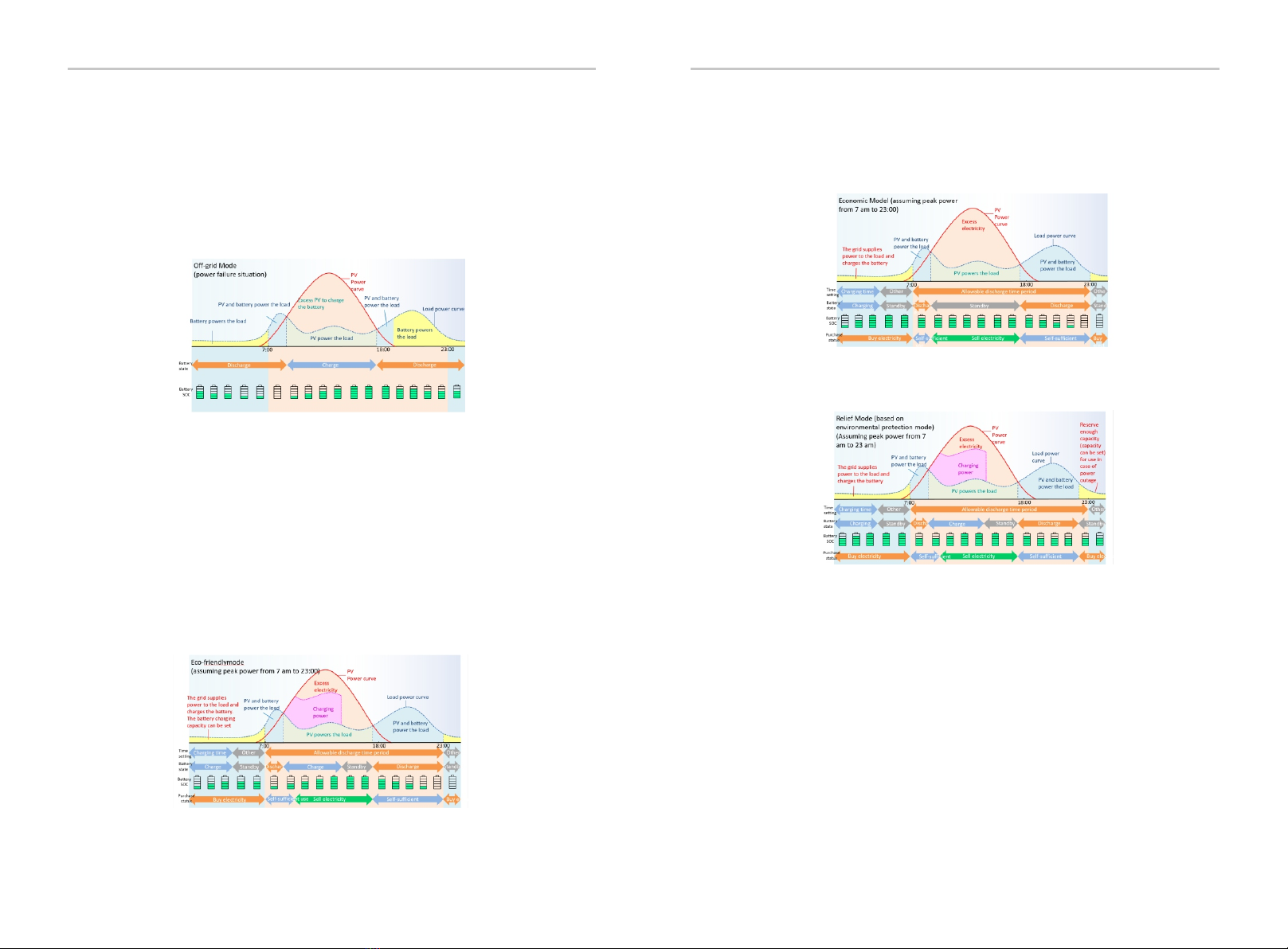
① Off-grid Mode
In the event of a power outage, the system will automatically switch to power
outage mode.If a specic load is overloaded, the error "independent operation
load protection" will be displayed. In this case, check whether the specic load
is within the possible range, if it is overloaded, reduce some load, and then
click the button of "standalone load protection" displayed in the current
error in the error history to clear it and restart normally system
② Eco-friendly Mode
In the daytime, the power generated by the photovoltaic power generation
panel is supplied to the household load,
Charge the surplus in the storage battery and use it during peak hours at night
and in the morning.
It is a eco-friendly mode that emphasizes the environment. Power generation
of photovoltaic power generation panel
If there is insufficient power or there is no generated power, start with the
storage battery.
Discharge. If the storage battery is fully charged, the surplus power will be
sold.
In addition, charging from the system is performed at midnight when
electricity charges are cheap, and it is released.
Electricity is installed during the time when electricity charges are high during
the day and electricity usage is at its peak.
By setting it, you can save on electricity charges.
④Relief Mode
In the relif mode, a certain amount of remaining battery power is secured so
that you can use it with peace of mind in an emergency. The basic operation is
the same as in green mode.
⑤Manual Mode
The manual mode has three functions: forced charge, forced discharge, and
forced charge / discharge stop. Manual mode is basically available only to
maintenance personnel.
Manual charging:
This mode charges the storage battery regardless of the time of day. For
manual charging, the system charges the battery with maximum power. The
battery is charged until it is fully charged, and after the battery is fully charged,
the storage battery is in a charge / discharge stop state.
Manual discharge:
This mode discharges the storage battery to the household load regardless of
the time of day. In the case of manual discharge, the system discharges from
the battery with maximum power. After full discharge, the storage battery will
be in the charge / discharge stop state.
Charge / discharge stop:
This mode does not charge or discharge the storage battery regardless of the
time of day. Solar power is still in operation. Operate each solar power
generation other than this product.
Note: If you set the manual operation mode and there is no operation for 6
hours, it will automatically switch to the operation mode (economic mode,
safe mode, or green mode) that was used before setting the manual operation
mode.
③Economic Model
In economic model, you can save electricity bills by charging the storage battery
at night when the electricity bill is cheap and discharging it from the storage
battery during the daytime when the electricity bill is expensive. If the surplus
power of solar power generation is sold in the daytime, the storage battery will
not be discharged. The storage battery will be charged within the set time zone.
(charging time zone can be set).
ABCDE F
HIJ
G
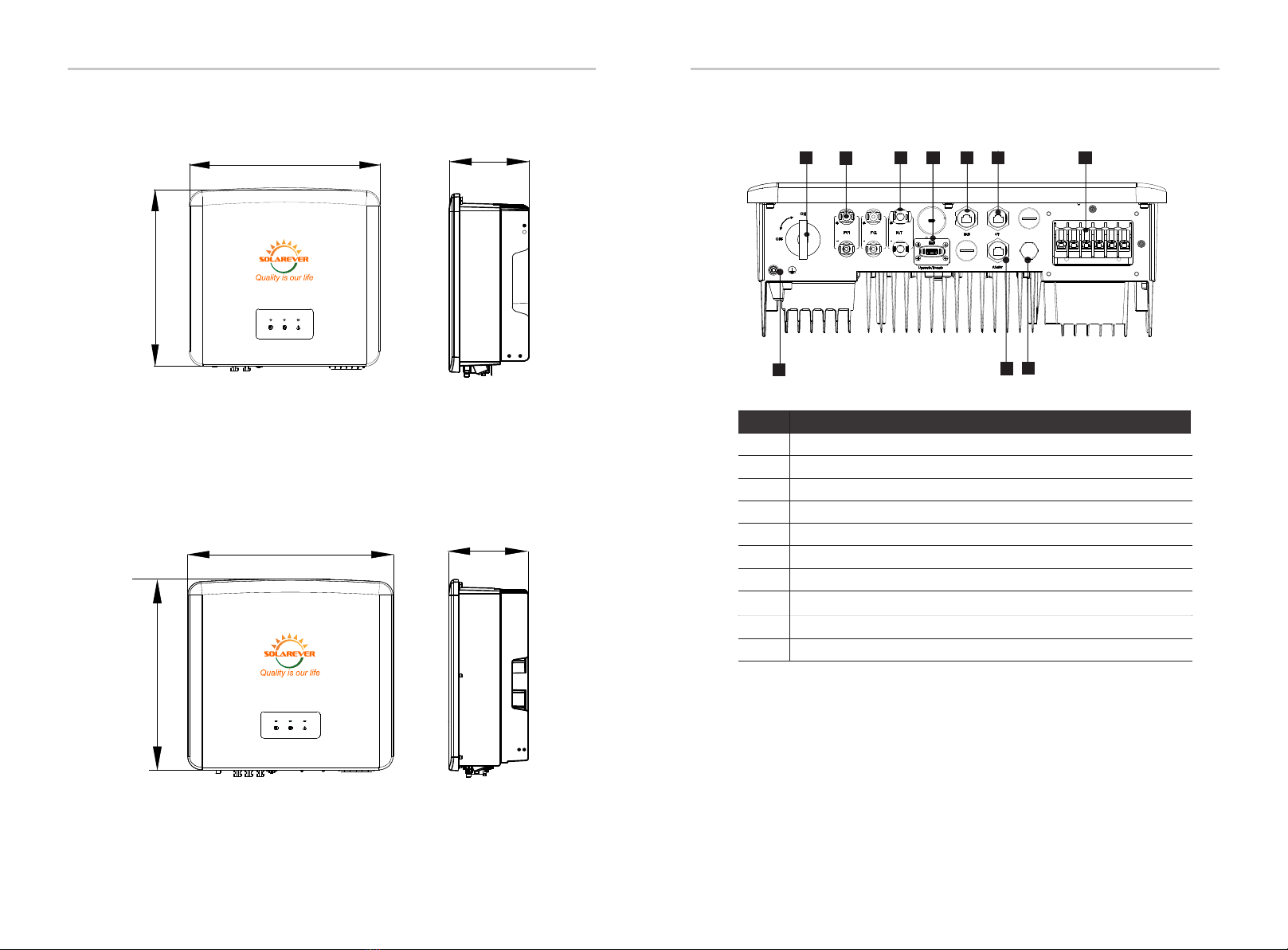
2.5 Terminals of Inverter
Object
A
B
C
D
E
F
G
H
I
J
DC switch
PV connection port
Battery connection port
CT Port
Load Output port/Grid Output port
Rs485 port
USB port for upgrading/ External monitoring connection port
Description
Battery communication port
Ground connection port
Waterproof valve
2.4 Dimension
482mm
417mm
181mm
IntroductionIntroduction
18 19
SE1-SPT3K&SE1-SPT3.6K
503mm 199mm
502mm
SE1-SPT3K&SE1-SPT3.6K
SE1-SPT6K&SE1-SPT7K
SE1-SPT6K&SE1-SPT7K
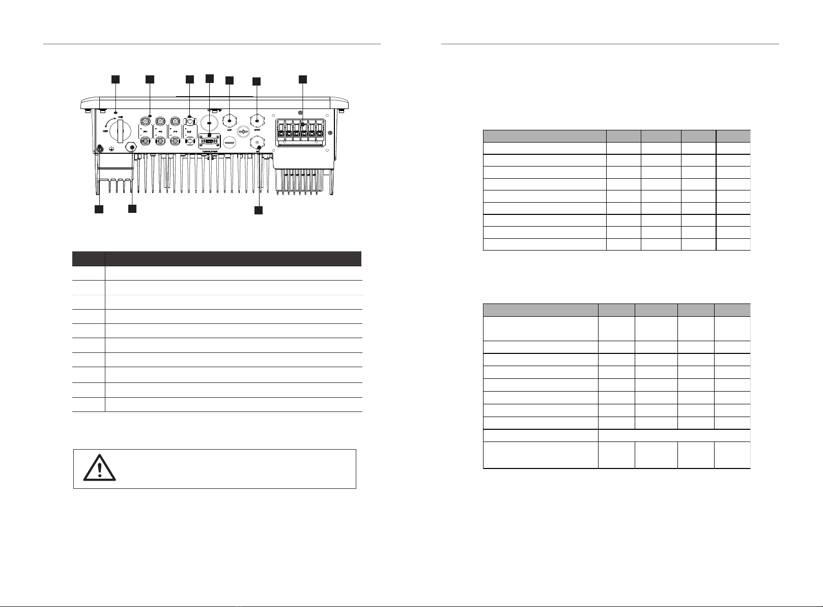
ABCEF
J
Object
A
B
C
D
E
F
G
H
I
J
DC switch
PV connection port
Battery connection port
Rs485 Port
Load Output port/Grid Output port
CT Port
USB port for upgrading/ External monitoring connection port
Description
Battery communication port
Ground connection port
Qualified electrician required for the installation.
Warning!
D3 Technical Data
3.1 Input PV
3.2 Output / Input AC
Module SE1-SPT-3K SE1-SPT-3.6K SE1-SPT-6K SE1-SPT-7K
Max.recommended PV panel power[W] 4500 5400 9000 10500
Max.DC voltage[V] 500 500 500 500
Norminal DC operating voltage[V] 390 390 390 390
Max. input current(per mppt)[A] 14/14 14/14 14/14/14 14/14/14
Max. short circuit current(per mppt)[A] 16/16 16/16 16/16/16 16/16/16
MPPT voltage range[V] 70-480 70-480 70-480 70-480
Start output voltage[V] 90 90 90 90
No. of MPP trackers 2 2 3 3
Strings per MPP tracker 1 1 1 1
Module SE1-SPT-3K SE1-SPT-3.6K SE1-SPT-6K SE1-SPT-7K
Rated grid voltage(AC voltage range)[V]
1Φ 3W
120/240
1Φ 3W
120/240
1Φ 3W
120/240
1Φ 3W
120/240
Rated grid Frequency[Hz] 50/60 50/60 50/60 50/60
Norminal AC outpout power[W] 3000 3600 6000 7000
Max. apparent AC output power[VA] 3000 3600 6000 7000
Norminal AC current[A] 12.5 15 25 29.2
Max. AC current[A] 14 16.5 29.5 29.5
Max. apparent AC input power[VA] 7000 7000 9300 9300
Max. AC input current[A] 29.2 29.2 39 39
Displacement power factor
Total harmonic distortion
(THDi, rated power)
<5% <5% <5% <5%
0.8 leading to 0.8 lagging
Technical DataIntroduction
20 21
I
G
H
Waterproof valve
Technical Data Technical Data
3.3 Battery
3.4 Load output (with battery)
22 23
Module SE1-SPT-3K SE1-SPT-3.6K SE1-SPT-6K SE1-SPT-7K
Battery voltage range[V] 100-480 100-480 100-480 100-480
Max.charge/discharge current[A] 30 30 30 30
Max. discharge power[W]* 3000 3600 6000 7000
Max. charge power[W]* 3000 3600 6000 7000
Communication interfaces CAN/ RS485 CAN/ RS485 CAN/ RS485 CAN/ RS485
Reverse connect protection YES YES YES YES
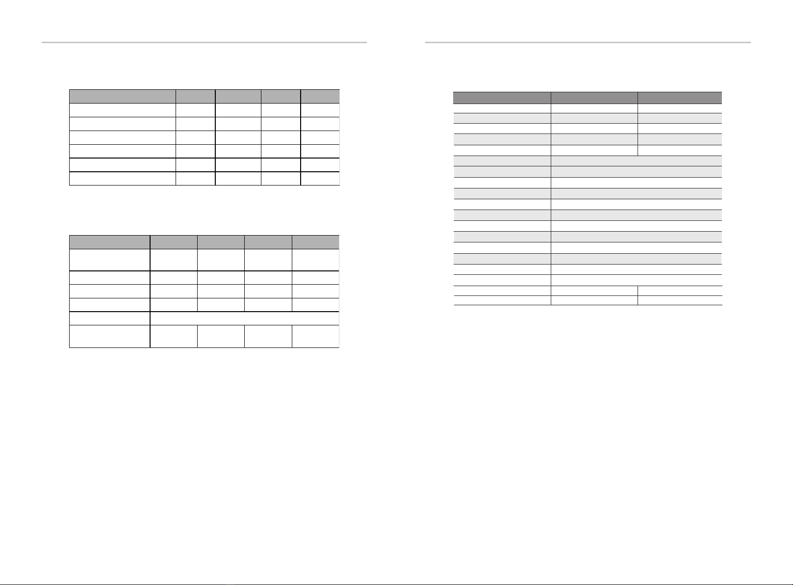
3.5 Efficiency, standard, environment limit and others
Module SE1-SPT-3K SE1-SPT-3.6K SE1-SPT-6K SE1-SPT-7K
Load rated voltage[V] 1Φ 3W
120/240
1Φ 3W
120/240
1Φ 3W
120/240
1Φ 3W
120/240
Load rated Frequency[Hz] 50/60 50/60 50/60 50/60
Load rated power[VA] 3000 3600 6000 7000
Load rated current 12.5 15 25 29.2
Load peak power[VA]
Total harmonic distortion
(THDv, linear Load) <5% <5% <5% <5%
100%~110%,10min;110%~120%, 1min;cannot exceed 120%
MPPT efficiency
Max eciency from PV to AC
99.9%
Module SE1-SPT 3-3.6k
UL1741
SE1-SPT 6-7k
Max eciency from PV to Battery
Max eciency from Battery to AC
Max eciency from AC to Battery
Satety
IP class
Protection class
Operating temperature range[℃]
Storage temperature[℃]
Humidity[%]
Altitude[m]
Noice emission(typical)[dBi]
Over voltage category
Cooling concept
Topology
Communition
Dimensign[mm]
Net weight[kg]
99.9%
97.0% 96.5%
97.0%
96.0%
96.0%
96.0%
96.0%
97.4%
Ip65
Class
-25℃~+60℃(derating at +45℃)
-25℃~+60℃
0 100(condensing)
<2000
<30
Ⅲ(AC),Ⅱ(DC)
Nature cooling
Transformerless
Rs485 CT*2 Dry contact(both for input and output)
482*417*181 502*503*199
24 31

4 Installation
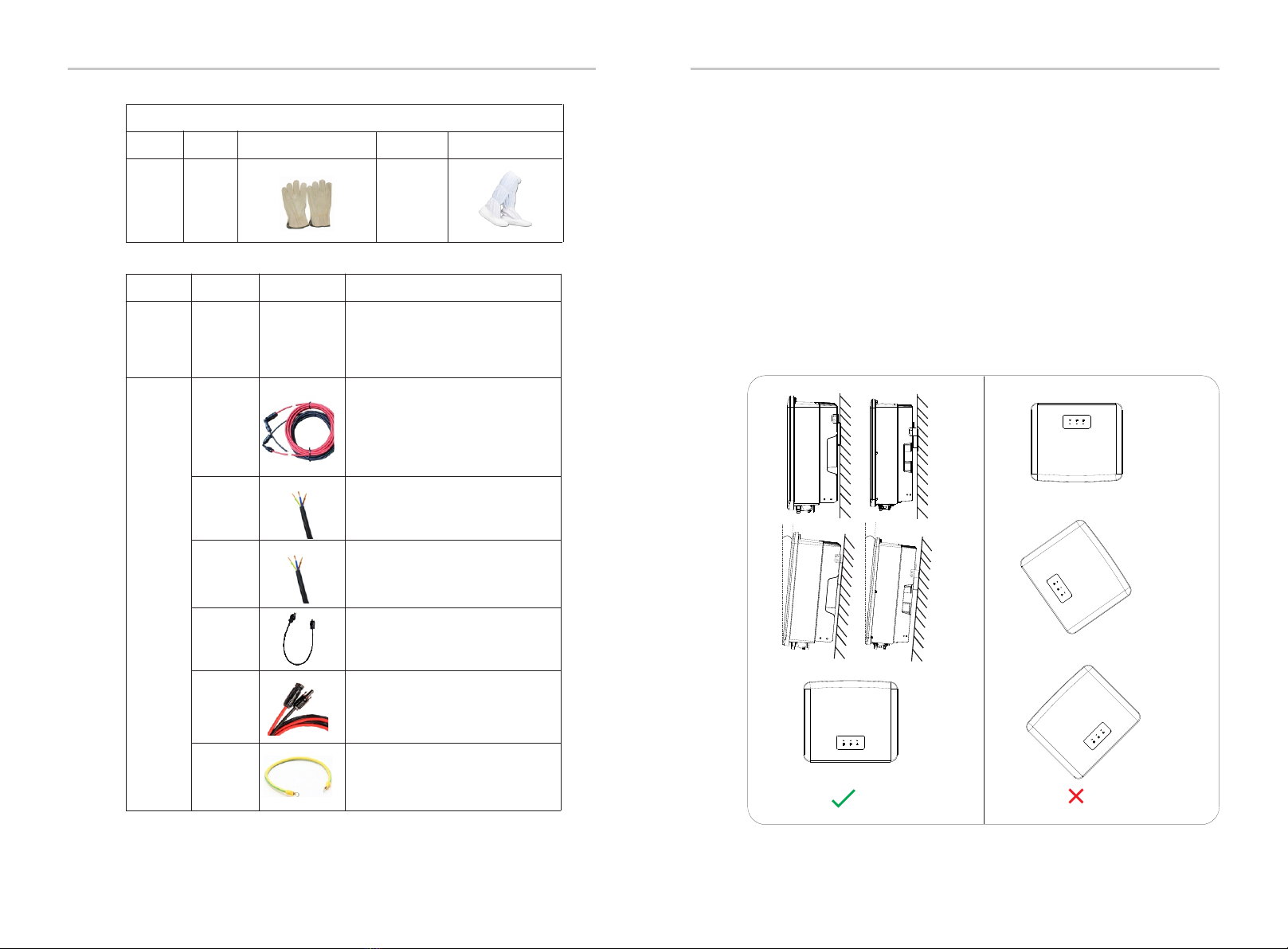
4.2 Packing List
Ensure that the inverter is in good condition via transportation. If there
is any visible damage such as cracks, please contact the dealer
immediately.
Open the package and check the materials and accessories
according to the following list.
AB C D
EFG
SE1-SPT Series 3.0KW-7.0KW
MN O P
4.1 Check for Transport Damage
IJKK L
Installation
25
24
Installation
1A
B
C
D
E
F
H
I
J
K
1
1
4
2
7
3
4
1
Quick Installation Guide
Description
L
M
2
10AWG Protective line casing
Number Quantity
SE1-SPT series inverter
Bracket
Waterproof connector
PV terminal (positive*2 , negative*2 )
Waterproof connector with RJ45 (COM/CAN/CT)
10AWG terminals
(Expansion bolt, Gasket, Self-tapping bolt)*5
Battery connection terminals(positive*1, negative*1 )
N1
O11
P1
Rj45 connector
Manual
5
Q
1
7
CT
3
M5 inner hexagon bolt
PV pin angle(positive*2, negative*2)
RJ 45 terminals
QR
6D
E
F
G
Q
R
6
4
3
3
4
Description
Number Quantity
10AWG terminals
8AWG terminals
PV terminal (positive*3 , negative*3 )
PV pin angle(positive*3, negative*3)
8AWG Protective line casing
10AWG Protective line casing
H
Description
Number Quantity
These are differences between SE1-SPT 3-3.6k and SE1-SPT 6-7k
SE1-SPT 3-3.6K
SE1-SPT 6-7K
S
S5 (Expansion bolt, Gasket, Self-tapping bolt)*5
SE1 -SPT
Use r Manua l
3.0kW - 7.0kW
UL
Copyright Declaration
www.solarever.com.mx

The protection level of SE1-SPT series inverters is IP 65, so that the inverter
can be installed outdoors.
Check the installation environment and pay attention to the following
conditions when installing:
• Do not expose to strong light.
• Do not touch flammable building materials.
• Do not approach flammable and explosive gases or liquids (e.g. where
chemicals are stored).
• Do not touch cold air directly.
• Do not approach TV antenna or cable.
• Do not place in areas above 2000 meters above sea level.
• Do not install in precipitation or high humidity, which may cause
corrosion or damage Internal devices.
• Keep the system out of reach of children.
If the inverter is installed in a narrow area, be sure to reserve appropriate
space for heat dissipation.
The ambient temperature of the installation site is -25 ~60 .°C °C
The maximum angle range of wall tilt ±5°.
Avoid direct sunlight, rain and snow weather.
No direct sunlight No Rain Exposure No snow Lay up
Direct Sunlight Rain Exposure Snow Lay up
4.3 Installation Precautions
Stay away from
antenna cables
Stay away from
combustibles
InstallationInstallation
26 27
4.4 Tool preparation
Type
Machine Installation Tools
Tool equipment
Bit Φ10
Name Image
Hammer
drill
Socket
wrench set
(Hexagon)
Torque
screwdriver
Name Image
Utility knife
Diagonal
pliers
Multifunction
terminal
crimping
tool (RJ45)
Multimeter
Marker
Tape
measure
Protective
glasses
Dustproof
Cover
Individual
Protection
Tools
Rubber
hammer
OT
terminals
press clamp
0.5mm²~6mm²
European
terminal
crimping
tool
Hexagon
keys
Spirit level
Crimping
Tool
Crosshead M5
DC Voltage
Range ≥1100 V DC
Diagonal
poliers
InstallationInstallation
Type
Equipment
Preparation
Name Requirement
Image
Cable
Preparation
Breaker
PV end
wire
Load end
wire
Grid end
wire
Communi-
cation lines
PE Cable
Dedicated PV wire, line number
#12 AWG withstand voltage 1000V,
temperature resistance 105℃ fire
resistance grade VW-1
Battery
Cable
Triple Core Cables
Triple Core Cables
Grid port and Load port wiring
section (4.5.2)
Type
Tool equipment
Name Image Name Image
Safety
gloves
Safety
shoes
Individual
Protection
Tool
Twisted pair with shield
Conventional wire
Conventional wire
28 29
4.5 Installation Site Conditions
4.5.1 Installation Carrier Requirements
Do not install the inverter near flammable materials.
Please install the inverter on a solid object that can withstand the weight
requirements of the inverter and energy storage system.
Please be careful not to install the inverter in the plasterboard wall or
similar to the residential places with poor sound insulation ,so as not to
work with noise and interfere with the residents life in the morning.
4.5.2 Installation Requirements
Install the inverter at a maximum back tilt of 5 degrees, the inverter can
not be tilted forward, inverted, excessive back tilted or side tilted.
≤5°
≤5°
Use local
model standard
air switch

≥300mm ≥300mm ≥300mm
≥300mm
≥300mm
≥300mm
≥1000mm ≥1000mm
≥500mm
≥500mm
≥300mm
≥300mm
InstallationInstallation
≥300mm
≥500mm
≥300mm≥300mm 300mm
300mm
300mm
500mm
Position Min Distance
Left
Right
Up
Down
Reserved space dimensions of
installation
4.5.3 Installation Space Requirements
Reserve enough space when installing inverter (at least 300mm) for heat
dissipation.
For multi-inverter installation scenarios, the inline installation method is
recommended; when the space is insufficient, the recommended method of
installation in the form of "products"; it is not recommended to install multiple
inverters in stacks. If you choose stack installation, please refer to the installation
separation distance below.
30 31
≥300mm ≥300mm ≥300mm
≥300mm
≥300mm
≥300mm
≥1000mm ≥1000mm
≥500mm
≥500mm
≥300mm
≥300mm

InstallationInstallation
d)
Self-tapping
screws
Outer hexagon wrench
(Torque :9±0.2 N· m)
Gasket
b)
Expansion bolts
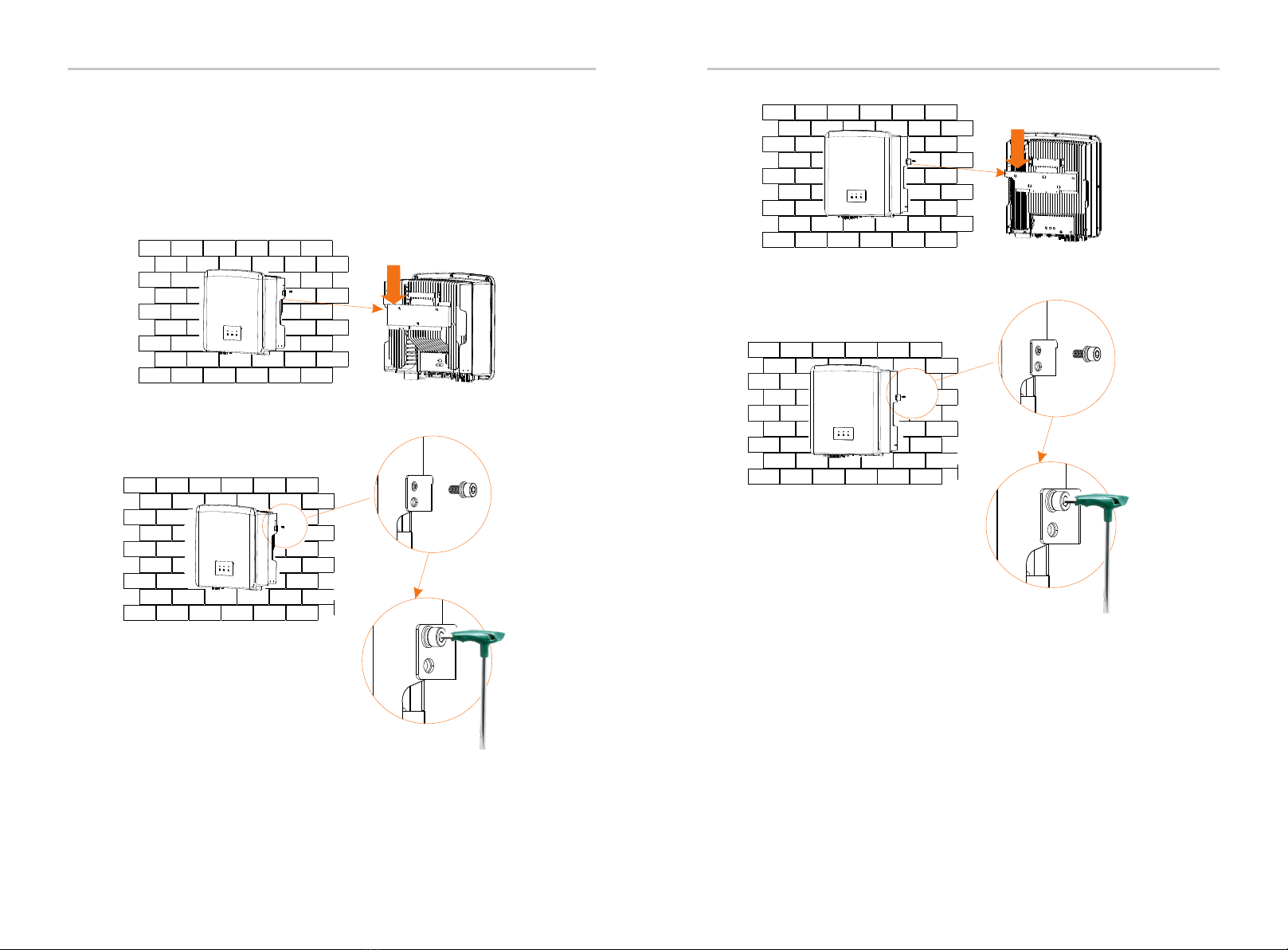
ØStep 2: hang the inverter on the bracket
c) Insert expansion bolt into the hole, use rubber hammer to knock the
expansion screw bolt into the wall;
d) The bracket is aligned with the screw uses the inner hexagonal
wrench to screw the tapping screw until the expansion bolt "bang" is
heard.
80.00 mm
Φ10 Drill
(Depth: 80 mm)
Rubber hammer
4.6 Mounting
ØPreparation
Ø Step 1: Fix the wall bracket to the wall
Please prepare the following tools before installation.
Installation tools: screwdriver, wrench, Φ10 drill, rubber hammer, socket
wrench set and Hexagon keys.
First find the expansion screw and the wall bracket in the accessory bag,
as shown below:
a)
Expansion bolts, Gasket, Tapping screws
Bracket
a) Use a marker to mark drilling holes of the bracket on the wall .
b)Drill holes at marked spots with depth of 80mm.(SE1-SPT 6-7K need 5
holes).
32 33
Expansion bolts, Tapping screws, nut, Gasket
Bracket
It consists of four parts
c)
Hammer
Expansion bolts, Tapping screws,
nut, Gasket,
e)
f )
ØStep 3: Tighten the inverter and bracket
Inner hexagonal wrench
(Torque :1.2±0.1 N· m)
Installation
34 35
e) Hang the buckle on the inverter to the corresponding position of
the backplane;
f ) Use the inner hexagonal wrench to tighten the inner hexagonal
screw on the right side of the inverter.
Installation
e)
f )
Inner hexagonal wrench
(Torque :1.2±0.1 N· m)
Electrical Connections
Please select photovoltaic modules with good performance and
quality assurance. The open circuit voltage of the module array should
be less than the maximum PV input voltage specified by the inverter,
and the working voltage should be within the MPPT voltage range.
Table 1: Maximum input voltage limit
Warning!
The voltage of photovoltaic modules is very high, and is
dangerous voltage. When wiring, please follow the safe
electricity regulations.
Notice!
Do not ground the positive or negative pole of the
photovoltaic module!
Notice!
The following PV module requirements need to be applied to
each input range:
1. Same model
2. Same quantity
3. The same queue
4. The same angle
5.1 PV Connection
Max. DC input voltage 500V
Model
Notice!
SE1-SPT series inverters do not support the following PV
module connection modes.
Inverter
PV
PV1
PV2
+
-
+
-
+
-
+
-
+
-
x
SE1-SPT 3k SE1-SPT 3.6k SE1-SPT 6k SE1-SPT 7k
√Inverter
PV
PV1
PV2
+
-
+
-
+
-
+
-
+
SE1-SPT series inverters support the following PV
module connection modes.
5 Electrical Connections
Electrical Connections
36 37
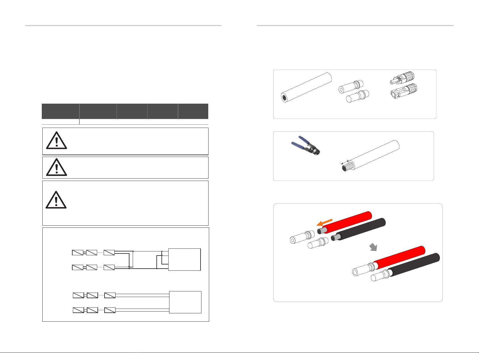
7.0mm
Step 1. Turn off the DC switch, connect the PV module, prepare a 12AWG
PV cable, and find the PV (+) terminal and PV (-) terminal in the package.
Step 3. Tighten the cable with the insulation layer stripped and insert it into
the metal terminal (see Figure 1), make sure all wires are inserted Into the
metal terminal (see Figure 2).
Step 2. Use a wire stripper to strip the 7mm insulation layer of the wire end.
Wire stripper
Figure 1
Figure 2
ØConnection step
PV cable PV pin Negative terminal
Positive terminal
Positive PV pin
Negative PV pin
Positive metal terminal
Negative metal terminal
This manual suits for next models
4
Table of contents
Popular Inverter manuals by other brands


SolarEdge
SolarEdge SE2200 installation guide

GW Instek
GW Instek USG-LF44 user manual

Koshin America Corporation
Koshin America Corporation GVH-3000 Operation manual

LG
LG N1T-V Series installation manual

SycoTec
SycoTec easyDrive 4624 Description

Olimpia splendid
Olimpia splendid DC 18 HP Instructions for installation, use and maintenance