OFF
ON
HEAT
COOL
MANUAL AUTO
/
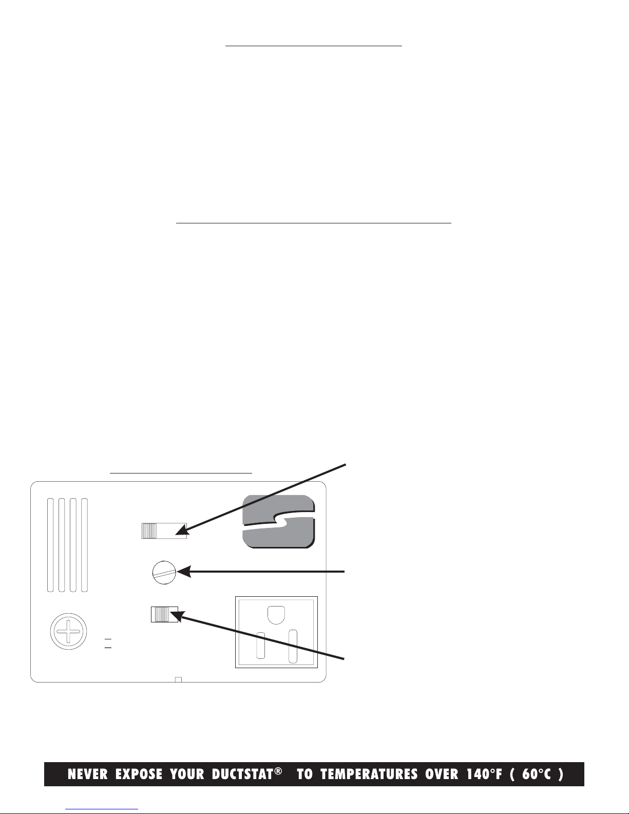
FUSE
5A at 125Vac Plug-In Thermostat™
®
Model DS100
DuctStat
OUTLET
SUNCOURT
maximum load
5A at 125Vac
SET POINT
Do not force
A
I
R
T
E
M
P
S
E
N
S
I
T
I
V
I
T
Y
MIN MAX
SENSITIVITY
DIFFERENTIAL
INSTALLATION NOTES
INSTALLATION INSTRUCTIONS
CONTROL PANEL
In order to prevent excessive strss on the mounting screws support the DuctStat® unit when unplugging connected devices.
DO NOT use the DuctStat® outdoors or in damp locations. DO NOT use the DuctStat® in an attic or crawl space.
The DuctStat® is intended to control the automatic on/off operation of In-Line Duct Fans™ installed in the ductwork of forced air
distribution systems.
The DuctStat® can also control the line voltage to any electrical device with a maximum current draw of 5 Amperes.
The DuctStat® is equipped with an external, replaceable 5 Amp fuse to protect the electronic circuitry from overload or short circuits.
This unit is equipped with a three-prong grounded plug. DO NOT attempt to defeat the ground feature of this plug. Defeating this will
void the warranty.
1. Locate the position between the In-Line Duct Fan™ and the register where you wish to lo mount the DuctStat®.
Mount between 1 and 10 feet downstream from the In-Line Duct Fan™.
2. Tape the template supplied with the DuctStat®to the air duct to mark the mounting holes to be drilled.
3. Drill a hole in the air duct for the Air Intake Hole shown on the template. This hole should be ½" in diameter.
4. Drill holes in the air duct to line up with the appropriate holes located on the template. On round ducts, two screws
placed through the slots in the DuctStat® unit's base will be adequate (placement shown on template).
or rectangular ducts use four screws, one at each corner of the DuctStat®(placement shown on template).
5. Tighten the supplied screws snugly in the appropriate placement fo your ductwork. DO NOT OVER TIGHTEN.
6. Wire a grounded power cord to the In-Line Duct Fan™ and plug into the outlet on the face of the DuctStat® unit.
7. Plug the DuctStat® power cord into a 110 volt grounded household outlet.
8. Follow Operation/Settings to adjust the DuctStat® unit.
Function switch selections:
OFF to stop operation of the In-Line Duct Fan™
ON for continuous operation of the In-Line Duct Fan™
AUTO HEAT for automatic on/off to boost warm air.
AUTO COOL for automatic on/off to boost cool air.
The rotary Set Point knob selects the automatic on/off
temperature setting for both heating and cooling.
The Sensitivity Differential switch
provides control over on/off cycling.