2
Subject to technical modification
02.2008
ASSEMBLY INSTRUCTIONS
ELECTRO CURTAIN TRACK SYSTEM 5060
Tear drive runner unit through rail by means of a mounting hook 301 463 until a flush top rail position (3). Measure the correct
length of toothed belt and cut it correspondingly by means of a side cutter:
length of blind up to 7000 mm overlapping at the rail end (ds) 97 mm
length of blind exceeding 7000 mm overlapping at the rail end (ds) 93 mm
Once cut to the right measure, you may now put on the rail gear in its position: tear out the outstanding end of the tape a bit
more, lead it through the rail gear and plug a second drive runner flush on at the end. Insert the drive runner into the rail and plug
on the gear.
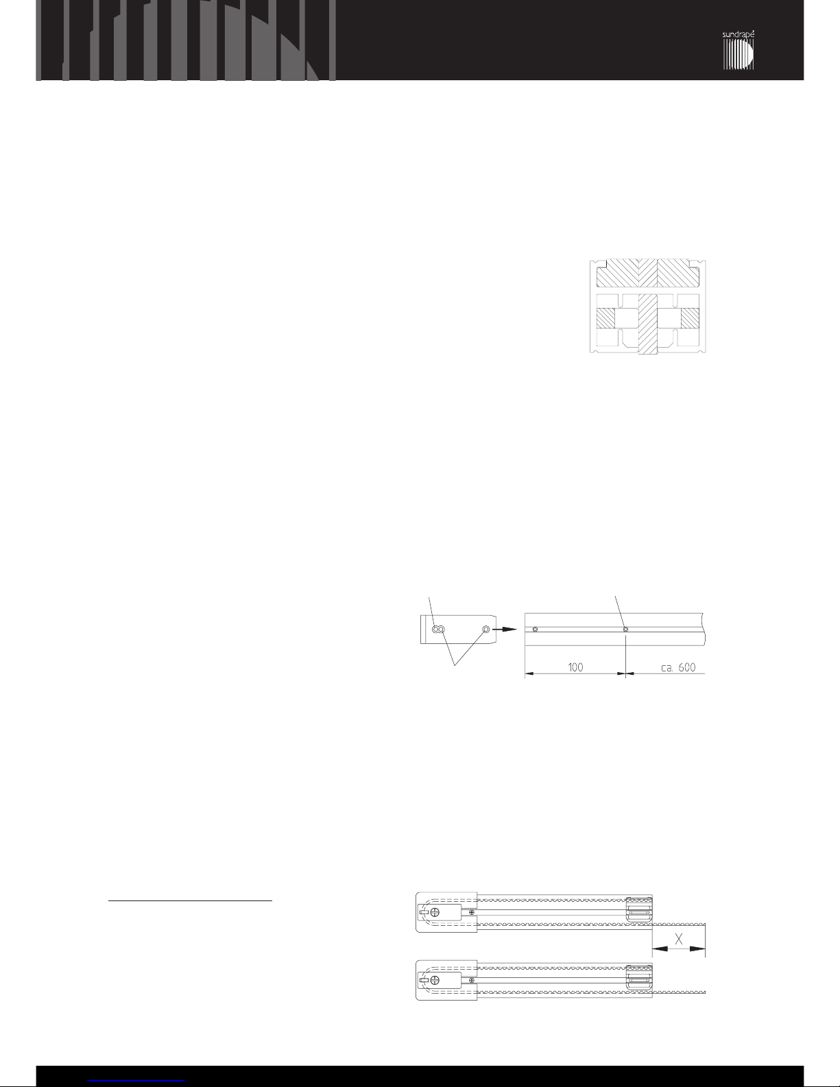
The toothed belt length is measured in a right way when the drive runners are standing at 6 to 8 mm to each other.
Toothed belt drive, two-part fabric:
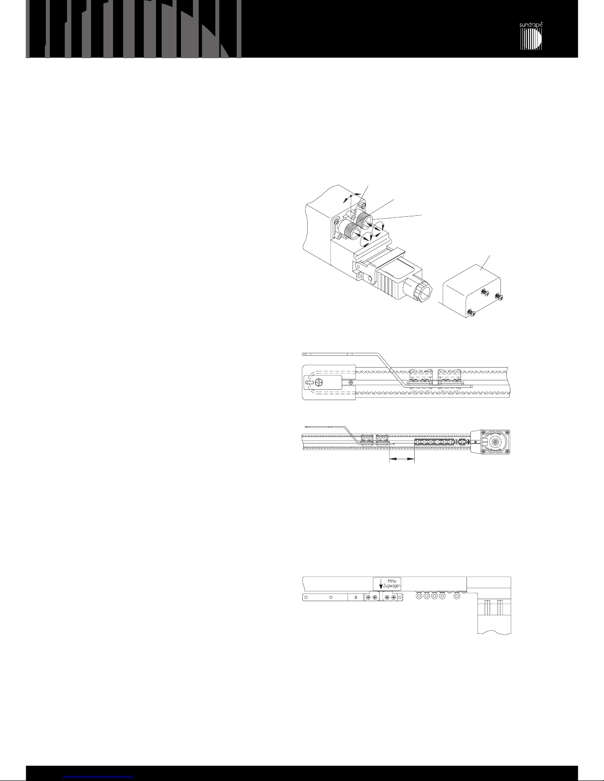
Proceed as described for “one-part fabric”. Then
sign the middle of the rail with a pencil and tear
drive runner exactly to the middle of the rail (4).
Then sign this center position on the belt by
means of a laquer pen (remove overrun colour).
Now remove rail gear and counter bearing and
plug in nds-drive runner with traverse joint
exactly at the sign you previously made with the
laquer pen (5). Then, by means of the mounting
hooks, move the drive runners towards each
other, plug on rail gear and counter bearing
again and assemble ds-drive runner with tra-
verse joint, fix with clip. Finally, move both drive
runners with traverse joint to the middle: both
traverse joints meet exactly in the middle (6).
Advice: According to operating side, insert left or right traverse joint, in case of center closing blinds, use two left or two right
traverse joints. The edge of the traverse joint always shows to nds-side respectively in case of center closing blinds to the
middle of the rail.
6.
Fix rail gear, counter bearing (in case of tandem motor: two rail gears) and rail profile from inside with one countersunk screw
each, 2,9 x 9,5.
7.
If necessary, tear traverse joint away from ds gear by hand so that the runners can be inserted.
8.
Insert the corresponding number of drive run-
ners or gliders (type of runner depends on type
of blind) through gear aperture into the rail. In
case of center closing blinds, remove cover of
counter bearing at nds-side. Fix the very first
roller or glider at ds-side and nds-side at 95 mm
by means of a locking device (7). Insert the
locking devices in the same way as the runners
or gliders: through aperture of gear. After this
process, screw cover of counter bearing on
again.
(4)
(4)
(6)
(7)
(5)
sign middle of the rail
put drive runner on the mark
middle off the rail
port for runners or gliders
mark belt with laquer pen
mark