Sunlover oasis IX9 Instruction Manual

-

Page 1 of 43
Quick Reference
Record your details here:
Please record the information below during installation as this will be required for any service or warranty
related work that may be required.
Please contact your local distributor or contact Oasis
directly and we will either direct you to your nearest
authorised repairer for assistance.
•contact Oasis on 1800 815 913 or via our Service
Request page on our web site;
•provide a copy of your invoice as proof of purchase;
•provide further information relating to the issue,
including any photos or videos;
•have completed the online warranty registration or
provide a completed warranty card.
Online Warranty Registration
Registering your Oasis Heat Pump is fast and easy,
providing peace of mind that you’ve got great backup
support for the life of your pool heating!
•Scan QR Code,
•No Need to create an account,
•Fill in your details,
•Upload a photo of the serial number,
•Submit.
https://sunloverheating.com.au/service-request/warranty-registration/
Model No:
Serial No:
Purchase Date:
Installer:
Warranty Registered Online:
Yes / No
Date Registered
/ / 20

Page 2 of 43
Table of Contents
3
Introduction
4
Important Things to Note
5
Specifications
7
Quick Start Guide
9
Safety
10
Location of Installation and
Airflow Clearance
11
Air Deflector Installation
12
Installation & Connection
17
Controller Operation
24
Troubleshooting
27
Maintenance
33
Technical Support
34
Warranty

Page 3 of 43
Introduction
Congratulations on your
recent purchase of your
Oasis Heat Pump.
Please take a moment to
read through the entire
manual before installing
your new unit.
This manual contains allthe necessary information
in regard to the installation, troubleshooting,
operation and maintenance of this unit.
Ensure instructions in this manual are adhered to
at all times. Failing to comply with these
recommendations will invalidate the warranty.
While every effort has been made to ensure that
the information contained in this manual is
accurate and complete, no liability can be
accepted for any errors or omissions.
There are 7different size models in our range:
Single Phase
Three Phase
iX9
iX13
iX19
iX24
iX28
iX28T
iX36T
The Oasis heat pump is the ideal choice for
recreational pool & spa owners looking to extend
their swim season with minimal running costs.
Designed with the latest technology including
stepless full DC inverter compressors, fans, and
control systems –the Oasis iX series is the energy
efficient and environmentally friendly way to enjoy
a longer swim season.
It is important that you read through the
manual to identify the key areas you need to
understand, particularly the following:
•Health and Safety Concerns
•Installation requirements
•How to operate the major features of the
unit
•The importance of maintenance
•If you have a problem, what you can do
to trouble shoot before you contact your
pool professional
•Your entitlements under the product
warranty.
Thank you again for choosing an Oasis Heat Pump.
Please note: Oasis reserves the right to change the specification of the hardware and software described herein at any time
without prior notice. This manual has been designed to cater for installation rules and codes in Australia. Specific rules and
regulations for other countries may differ. Please speak with your installer should you have any questions.

Page 4 of 43
Important Things to Note
Check that you have received the package in good condition
Ensure you meet the minimum clearances and recommended installation locations as outlined in the
manual. Make sure that the unit is installed as per the ventilation diagrams to ensure efficient heating
All accessories (drain barbs, rubber feet and barrel unions) and the installation manual is contained in
a plastic bag inside the packaging of your heat pump
Please refer to the warranty section of this manual and follow the outlined registration process
To avoid voiding your warranty, please refer to the maintenance requirements outlined in the warranty
section of the manual
The time it takes to INITIALLY heat up your pool will be influenced by factors such as the pool's size,
environmental conditions, and the installed system's capacity
The Heat Pump unit discharges condensation water from the bottom, similar to a household air
conditioner, and requires regular inspection of the condensate drain to detect any obstructions or
debris accumulation. It is important to keep the drain clean to allow for smooth condensate flow and
proper discharge to the drainage system
If a Wi-Fi enabled controller has been installed, make sure that the heat pump area has sufficient
2.4ghz Wi-Fi signal strength
Under no circumstances should an unlicensed person attempt to install or repair an Oasis heat pump
themselves
Use genuine Oasis spare parts only. Failure to comply with these recommendations will invalidate the
product warranty
For any technical questions or additional information please contact your local distributor or contact
Oasis directly
Directive 2002/96/EC (WEEE)
The crossed-out waste bin symbol under the appliance indicates that it should not be thrown away with
regular household domestic waste at the end of its useful life. Instead, it should be taken to an
electronic recycling centre or returned to the dealer when you buy a new one
Directive 2002/95/EC (RoHs):
This product is compliant with directive 2002/95/EC (RoHs) concerning restrictions for the use of
harmful substances in electric and electronic devices.

Page 5 of 43
Specifications
The data presented relates exclusively to the Oasis heat pump and excludes any auxiliary equipment. The product
specifications mentioned above were precise at the time of printing, but are subject to change without prior notice.
For the latest and most accurate information, please contact an Oasis heat pump specialist.
iX9
iX13
iX19
iX24
iX28
iX28T
iX36T
Performance Data
Air 27°C
Water 26°C
Heating Capacity
kW
1.6 ~ 9.4
2.13 ~ 12.8
2.9 ~ 18.9
3.1 ~ 24.6
5.8 ~ 28.0
5.5 ~ 28.9
5.7 ~ 36.0
Consumed Power
kW
0.11 ~ 1.6
0.15 ~ 2.0
0.42~ 3.1
0.21 ~ 3.9
0.36 ~ 4.2
0.38 ~ 4.5
0.34 ~ 5.4
COP
14.5 ~ 6.0
14.2 ~ 6.4
14.5 ~ 6.1
14.8 ~ 6.3
16.4 ~ 6.7
14.5 ~ 6.4
16.8 ~ 6.7
Air 15°C
Water 26°C
Heating Capacity
kW
1.0 ~ 6.6
1.8 ~ 9.1
2.4 ~ 12.5
4.4 ~18.6
5.2 ~ 21.7
6.4 ~ 21.4
5.3 ~ 27.0
Consumed Power
kW
0.14 ~ 1.35
0.26 ~ 1.9
0.34 ~ 2.6
0.6 ~ 3.7
0.7 ~ 3.9
0.9 ~ 4.2
0.7 ~ 5.1
COP
7.1 ~ 4.9
6.9 ~ 4.8
7.1 ~ 4.8
7.3 ~ 5.02
7.4 ~ 5.6
7.1 ~ 5.1
7.6 ~ 5.3
Air 35°C
Water 29°C
Cooling Capacity
kW
1.9 ~ 3.2
2.5 ~ 3.6
4.4 ~ 7.7
5.0 ~ 12.3
3.9 ~ 10.4
5.8 ~ 14.5
5.0 ~ 12.7
Consumed Power
kW
0.7 ~ 1.3
0.8 ~ 1.2
1.5 ~ 3.1
1.5 ~ 3.9
1.3 ~ 4.7
1.8 ~ 4.7
1.5 ~ 4.4
EER
2.7 ~ 2.5
3.1 ~ 3.0
3.3 ~ 2.9
3.0 ~ 2.2
3.2 ~ 2.8
3.2 ~ 2.8
3.4 ~ 2.9
Technical Specifications
Operating air temperature
°C
-7 ~ 43
PV Ready
Yes
Rapid Heat
Yes
Refrigerant
R32 GWP (global warming potential) –675
IPX rating
IPX4
Airflow
m3/h
2600
3000
3750
4500
6000
4500
7200
Sound Pressure at 1m
dB(A)
40 ~ 52
42 ~ 54
44 ~ 56
45 ~ 56
46 ~ 54
45 ~ 57
48 ~ 56
Net Dimensions
(L x W x H)
mm
934 x 360
x 618
934 x 360
x 618
1048 x 453
x 771
1160 x 490
x 865
1161 x 490
x 1277
1160 x 490
x 865
1161 x 490
x 1277
Net Weight
kg
42 / 54
44 / 56
60 / 74
87 / 103
111 / 132
99 / 115
120 / 137
Electrical
Power Supply
V/Ph/Hz
240/1/50
400/3/50
Electrical connection
10A plug
15A plug
Hardwired
Running Current input
(per phase)
amp
6.9
9.0
13.9
17.9
24.1
7.6
10.5
Water
Connection
mm
40
Flow Volume
l/m
42
58
70
110
125
135
160
Pressure Drop (max)
kPa
3.0
3.0
6.0
14.0
11.0
17.0
15.0

Page 6 of 43
Specifications
Unit Dimensions Unit: mm
iX9 / iX13
iX19
iX24 / iX28T
iX28 / iX36T

Page 7 of 43
Quick Start Guide
•Ensure you meet the minimum clearances and recommended installation
locations as outlined in the manual.
•All accessories (drain barbs, rubber feet and barrel unions) and the
installation manual is contained in a plastic bag inside the packaging of your
heat pump
Pre-Installation
1. Install the supplied rubber anti-vibration feet under the unit.
2. Position the heater on a level pad in the desired location on the pool water return line (as shown
in the example image below).
3. Install the supplied condensation barb(s) tothe underside of the unit anddirect the condensation
to an appropriate drainage point. The unit must sit level to allow condensation to drain correctly.
The schematic diagram is for reference only. Please check the water inlet/outlet label on the heat pump while plumbing the unit.
Plumbing Installation
PLEASE NOTE: The supplied fittings accept standard 40mm PVC pressure pipe.
1. Attach the supplied barrel unions to the inlet and outlet (hand tighten). Use plumbing tape on
the thread and ensure the O-rings are installed and lubricated with a silicone-based grease.
2. Install a 3-way valve at the cold-water inlet and create a bypass by connecting a “T” piece to the
heated line. This will allow for the adjustment of water flow to the unit.
3. Make the plumbing connections and brace pipework where necessary to prevent lateral strain
being applied to the unions. This will aid in preventing future leaks.

Page 8 of 43
Quick Start Guide
Electrical Connection
OASIS HEAT PUMPS MUST BE CONNECTED BY A LICENSED ELECTRICIAN
IN ACCORDANCE WITH ALL RELEVANT AUSTRALIAN STANDARDS,
APPLICABLE LAWS AND LOCAL LEGISLATIONS.
Under no circumstances should an unlicensed person attempt to install or repair an Oasis
heat pump themselves.
It is essential to ground the unit to safeguard against any short circuits that may occur inside
the unit. Additionally, bonding is necessary.
The unit has a separate moulded-in junction box with a standard electrical conduit nipple already in
place.
1. Remove the external cover to the electrical terminal by removing the screws and the terminal
cover panel.
2. Feed the electrical cable lines through the conduit nipple and attach the electric supply wires.
3. To completethe electrical connection, install electrical conduit, UF cableor other suitablemeans
as specified (as permitted by local electrical authorities) and connect the cable to a dedicated
power supply branch circuit equipped with appropriate circuit protection.
Disconnect
An isolating switch MUST be installed within close proximity and in plain sight of the unit.
Initial Startup & Commissioning
NOTE: The water pump must be running and water circulating through the heat pump for the system
to operate.
1. Turn on your water pump and check for water leaks and verify water flow to and from the pool.
2. Turn on the electrical power supply to the Oasis unit.
3. Press the ON/OFF key of the controller for half a second, the heat pump will start within 60
seconds.
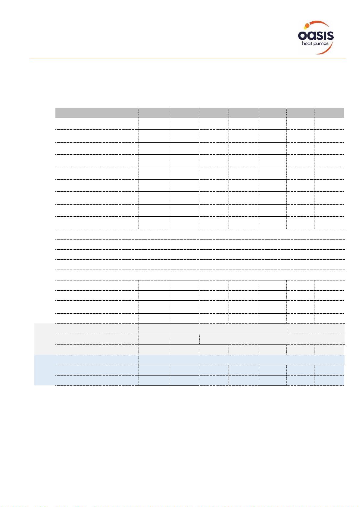
4. Adjust the bypass valve to set the water flow rate in accordance with the specifications on Page
5 of this manual. After 10 minutes of operation, the optimal flow rate will result in an inlet/outlet
temperature difference of between one and two degrees Celsius.
5. Once the unit is running, switch off the water pump. The unit should then shut down on its own,
which indicates the flow switch is functioning correctly.
6. Run both the unit and water pump continuously (night and day), until the desired water
temperature is reached.
7. When the water-in temperature reaches this level, the unit will decrease its speed for a specific
time. If the temperature remains constant for 45 minutes, the unit will shut down for one hour
and sample the water temperature each hour thereafter, proving there is water flow.
In the event that the pool temperature drops more than 0.5 degrees below the desired
temperature, the unit will restart automatically.

Page 9 of 43
Safety
Installation, repair, or relocations should be completed by a fully qualified technician.
If not carried out correctly, several hazards, such as fire, electric shock, water
leakage, and injury, may occur.
This appliance is not intended for use by persons (including children) with reduced physical sensory or
mental capabilities, or lack of experience and knowledge, unless they have been given supervision or
instruction concerning use of the appliance by a person responsible for their safety.
•A circuit protection device must be installed for the unit.
•To avoid risk of electrical shock, the unit must have a good power connection and earthing.
•Before obtaining access to terminals all supply circuits must be disconnected.
•The unit is equipped with an over- load protection system. After a stoppage, the unit will not start
for at least 3 minutes.
•Do not use any means to accelerate the defrosting process or to clean other than those
recommended by the manufacturer.
•If installing in an enclosed area, the equipment should be kept away from any sources of ignition.
This includes items such as open flames, operating gas appliances, or operating electric heaters.
Any refrigerant leakage can potentially result in a fire hazard.
•Do not pierce or burn the unit.
•Be aware that refrigerants may not contain an odour.
•If the supply cord is damaged, it must be replaced by the manufacturer, a qualified service agent
or similarly qualified persons in order to avoid a risk.
•This appliance must be installed in accordance with national wiring regulations.

Page 10 of 43
Location of Installation and
Airflow Clearance
Before installation it is very important to ensure these five variables are carefully checked to allow the unit
to operate correctly.
1. Heater condition
2. Clearances & air flow
3. Location
4. Adequate water flow & plumbing
5. Correct electrical connection & supply
To ensure optimal performance and prevent potential
damage, the heat pump unit requires continuous fresh air
while running.
The heater, which draws up to 80m3/min of ambient air
through the sides and discharges it through the top fan
cowl, must not be installed indoors or in an enclosed
space without adequate ventilation. Doing so can result
in poor performance, and in extreme cases, damage to
the heater.
Locating the heater in an enclosed area will cause
discharged cold air to recirculate into the unit, lowering
heating efficiency and potentially causing icing up.
•Heat Pumps should ONLY be installed in an outdoor location with appropriate ventilation.
•Ensure the heater is installed in a well-ventilated area with plenty of fresh air.
•Leave sufficient space for unobstructed airflow into and out of the heater.
•At least 3.5m away from the water’s edge.
•No greater than 7.5m from the water’s edge (to avoid heat loss from the piping).
•No greater than 5.0m below the water level of the pool/spa.
•Ensure the heat pump is not installed close to harsh or corrosive chemicals.
•The heat pump MUST be installed on a flat level surface (the feet supplied are adjustable).
•A minimum gap between walls/fences etc of 200mm on the back and sides and 500mm overhead
and 1000mm on the front clearance.
Make sure the heat pump is not located where large amounts of water may run-off from a roof into the unit.
Sharp sloping roofs without gutters will allow excessive amounts of rain water mixed with debris from the
roof to be forced through the unit. A water deflector may be needed to protect the heat pump.
Airflow
An air intake at the back of the unit draws warm ambient air, while a discharge fan at the front releases cold
air. In cases where an obstruction is within 1.0m of the front discharge of the installed unit, such as a wall or
fence, installation of a deflector redirects air flow upwards or sideways instead of directly towards the
obstruction.
Any space problem can be resolved easily with the optional purchase of a Sunlover Air Deflector to
redirect the cold discharge air away, creating ample ventilation and airflow in any area.
Please contact our Support Specialist to discuss appropriate installation locations or discuss how an air
deflector can assist.

Page 11 of 43
Air Deflector Installation
Sunlover offers Air Deflectors as an optional purchase.
Recirculating the front air discharge back into the heat
pump's air intake should be avoided.
If there are space constraints, installing an Air Deflector
is a straightforward and economical solution.
NO PRE-DRILLING REQUIRED
Items required:
•Air Deflector/s
•Mounting hardware
4x 15 - 20mm long self tapping screws or tek
(metal cutting) screws per deflector
the screws should preferably be gal or stainless steel for long
term outdoor use
•Determine the appropriate placement. Ideally, the air
deflector should be installed perpendicular to direct air
upwards. However, a deflector can also be installed to
redirect air discharge to the side( see below example)
•Place the deflector level over the fan cage, positioning
with the large depth open end facing the direction
where the air is to be expelled, making sure that the
cage is completely enclosed and the deflector is level.
•The deflector is equipped with installation tabs on both
sides, each featuring three holes as illustrated above.
Once you have determined the best placement for the
screws, mark the location of the chosen holes on the
tabs using a marker for reference.
•Proceed to attach the deflector to the front of the heat
pump using long self-tapping or tek screws to secure,
taking care not to over-tighten the screws. This will
ensure that the deflector remains firmly in place and
directs the air flow as desired.

Page 12 of 43
Installation & Connection
Heater Condition
Upon receiving the heater, inspect its packaging thoroughly for any apparent signs of damage and
IMMEDIATELY notify your supplier if there are any signs of rough handling.
NOTE: All accessories (drain barbs, rubber feet and barrel unions) and the installation manual is
contained in a plastic bag inside the packaging of your heat pump.
Plumbing
The unit’s exclusive titanium heat exchanger requires no special plumbing arrangements except a
bypass.
Flow Rate
Ensure the water pump and plumbing is capable of meeting or exceeding the
required flow rate in accordance with the specifications on Page 5 of this
manual.
Location
Connect the unit in the pool pump discharge (return) line downstream of all filter
and pool pumps, and upstream of any chlorinators, ozonators or chemical
pumps.
Oasis heat pump models have quick coupler fittings which accept 40mm PVC pressure pipe for
connection to the pool or spa filtration piping.
Ensure pipework connecting to the inlet/outlet unions is appropriately supported as any lateral strain
may cause the rubber O-rings to pinch and leak.
Lubricate all O-rings with silicon grease prior to fitment and apply plumbing tape to the threads for
additional security.

Page 13 of 43
Installation & Connection
First Time Operation
When starting for the first time:
•Ensure the water pump is adequately primed.
•Adjust bypass valve to provide full flow to heat pump, which will aid in purging air from the
system.
•Switch on the water pump and thoroughly check all plumbing connections for leaks.
•Start the heat pump in accordance with the instructions on Page 8 of this manual.
The diagram provided is intended for informational purposes only.
It depicts all the essential parts required, which must be obtained by the installer or the user.
Adequate Water Flow
All heat pumps have a factory pre-set internal water flow switch. If there is insufficient water flow the
unit will not operate.
It is CRITICAL that there is sufficient water flow to the unit. Incorrect water flow can cause a loss of
efficiency and possible damage to the unit. Optimal water flow rates are listed on Page 5 of this
manual. It is imperative that water flow is kept as close as possible to these flow rates. Correct water
flow not only offers optimal heater performance but may also prevent possible damage to your heater.
As a rule of thumb there should be a minimum inlet/outlet temperature differential of one degree
Celsius and a maximum of two degrees Celsius.
Before connecting the heater to the plumbing, all piping must be thoroughly flushed to ensure no
debris can enter the heater. Failure to remove pipe debris can jam or damage the flow switch and
may cause damage to the heater. When cleaning the pool, it is advisable to turn off your heater as
restricted water flow may cause the heater to shut down and indicate low water flow fault (E03 error)
and/or a high refrigerant pressure fault (E01 Error).
A variable speed pump or bypass valve and plumbing MUST be fitted to allow water
flow to be adjusted through the heater. Do not directly connect a water pump with
higher flow than required to the heat pump.

Page 14 of 43
Installation & Connection
Time Delay
The unit is equipped with a 3-minute restart delay included to protect control circuit components and to
eliminate short cycling.
This time delay will automatically restart the unit approximately 3 minutes after each control circuit
interruption.
Initial Heat Up Time
Initial heat up times will vary depending on the size of your pool, environmental conditions and the
capacity of the system installed. After installation, please allow the unit and pool pump to run
continuously until the desired pool water temperature is reached (it may take several days for the pool
to initially reach the set temperature).
Once the pool water reaches the desired set temperature, the unit will shut off. The unit will
automatically restart (provided your pool pump is running) when the pool temperature falls more than
0.5°C below the desired set temperature.
Rubber Feet
All units are provided with rubber feet which we highly recommend being installed. The rubber feet
help reduce vibration of the unit and provide a space below the heat pump to install the drainage
barbs.
Condensate Drain Barbs
Fit the condensate drain barbs into the 2 holes under the unit if you need to direct
water away from the heater. If the barb is too stiff, place it in hot water to soften.
Drainage & Condensation
Whilst the heater is operating, water in the air condenses on the fins of the evaporator. In the instance of
high humidity, the condensate may be several litres per hour. This may give the impression that the heater
is leaking, however this is a normal function of heat pumps.
The heater will automatically activate reverse cycle or de-icing mode when required which also increases
condensate discharge. This normally occurs at temperatures below 8 deg C. As the ice melts from the
evaporator fins, water will be discharged through the base of the heater. As an option a pipe can be
connected to the drain on the base of the unit to direct condensate water to an appropriate location.
A quick way to verify that the water is condensation is to shut off the unit and
keep the pool pump running. If the water stops running out of the base pan
after several minutes, it is condensation.
Another method is to test the drain water for chlorine using a test strip. If
there is no chlorine present, it can be concluded that the discharge is
condensation.

Page 15 of 43
Installation & Connection
Electrical Connection
Ensure the power cable and circuit protection device are of a suitable size for the heater being
installed. Also check that there is adequate voltage and current available at the heater connection to
run the unit.
Voltage range should be 220-240 volts for single phase, and 380-415 volts for 3 phase units. Voltage
ranges outside these parameters will cause heater damage and void your warranty.
1. Ensure power is disconnected during installation or service.
2. Always comply with the national and local electrical codes and standards.
3. Ensure the electrical cable size is adequate for heater requirements at the installation location.
4. The heater must be equipped with appropriate circuit protection and isolation devices.
5. An additional circuit protection device must be installed between the heater and the water circulation
pump if a water pump is hard-wired into the heater. Please note recommended circuit breaker sizes
make no allowance for a water pump hard wired into the heater.
6. The unit must be well earthed. Remove the front panel to access the electrical connection terminals
of the heater. The electrical wiring diagram is affixed to the inside of the front panel or at the back of
this manual.
Heater electrical installation undertaken by an unlicensed installer will void the warranty.
Correct installation is required to ensure safe and efficient operation of your pool heater.
A licensed electrician must read the installation manual before connecting.

Page 16 of 43
Installation & Connection
PV Ready Integration
sunloverheating.com.au/pv-ready
For detailed information on the PV ready feature of the Oasis iX
heat pump, we have a separate manual available for download.
This manual specifically focuses on the installation, configuration,
and operation of the PV ready functionality, allowing you to
seamlessly integrate your heat pump with solar power systems.
By accessing this manual, you will gain valuable insights into
optimising the performance and energy efficiency of your Oasis iX
heat pump through the PV ready feature.
Feel free to download the manual, and you'll be equipped with the
knowledge to harness the full potential of this innovative
technology.
Wi-Fi Module
If you have chosen to upgrade your Oasis iX heat pump to include
the Wi-Fi Module, the comprehensive instruction manual has been
made available separately for convenient download.
This manual provides instructions on how to set up and utilise the
WIFI functionality of the heat pump, allowing you to control and
monitor the unit remotely.
By downloading this manual, you will gain a deeper understanding
of the available WIFI features and maximise the benefits of your
Oasis IX heat pump.
Take a moment to download the manual, and you'll be well-
equipped to make the most out of this advanced technology.
sunloverheating.com.au/wi-fi-module

Page 17 of 43
Controller Operation
Main Controller Interface
The heat pump is equipped with a digital control panel with a touch screen, electronically connected
and pre-set at the factory in heating mode.
1
Compressor indicator
12
Current time
2
Fan indicator
Normal Mode
13
Mode selection key
(Auto/Heating/Cooling)
Silent Mode
3
Timer indicator
14
Temperature adjustment setting
4
Current mode setting
(Auto/Heating/Cooling/Defrost)
15
Silent mode timer setting
5
Alarm indicator
16
Silent mode activation setting
6
Touchpad lock indicator
17
On/Off timer setting
7
Water outlet temperature
18
Access advanced settings
8
On/Off/Back
key
19
Access list of faults
9
Main (home) screen
20
Time and date setting
10
Setpoint temperature
21
Confirm selection
11
Water inlet temperature
22
Back/cancel (changes not saved)

Page 18 of 43
Controller Operation
OFF Mode
ON Mode
When the heat pump is inactive (in standby mode)
the screen is black. OFF is displayed, as shown
below.
When the heat pump is active (running or setpoint
reached) the screen is blue. The target
temperature is displayed as shown below.
To manually switch from OFF to ON mode and vice versa, press the key for 0.5 seconds.
If you have activated timers, the unit will automatically switch between OFF and ON in
accordance with those settings.
Mode Selection
To change the mode (heating / cooling / auto), swipe across to the right and touch the Mode key.
Select your desired mode and press OK to save.
Press once (x1) to return to the home screen.

Page 19 of 43
Controller Operation
Adjusting the Target Set Temperature
The setpoint can be changed in either ON or OFF mode in increments of 0.5°C.
To change the desired pool temperature, swipe across to the right and touch the Temp Setting key.
Adjust the temperature setting by swiping up and down and press OK to save.
Press once (x1) to return to the home screen.
Time and Date Settings
The setting for date and time can be configured in either ON or OFF mode.
To adjust the time and date, swipe across to the left and touch the Time Setting key.
Adjust the date and press OK to continue. Adjust the time (note this is a 24-hour clock) and press OK
to save.
Press once (x1) to return to the home screen.
This manual suits for next models
6
Table of contents
Other Sunlover Heat Pump manuals
Popular Heat Pump manuals by other brands

Viessmann
Viessmann VITOCAL 060-A Operating Instructions for the System User

REMKO
REMKO WSP Series Instructions for Technicians

evoheat
evoheat EVO 270 manual

Steinbach
Steinbach Waterpower 8500 user manual

Daikin
Daikin EGSQH10S18AA9W Installer's reference guide

Arcoaire
Arcoaire CHS180 installation instructions

Panasonic
Panasonic WH-SD24BE5 operating instructions

NextE
NextE CCE07 Installation, operation and maintenance guide

Carrier
Carrier 50JZ 024-060 Guide to operating and maintaining

Bryant
Bryant 543A Installation, stat-up and service instructions

VEAB Heat Tech
VEAB Heat Tech AW DX22 manual

Dimplex
Dimplex SI 24TE SI 37TE Installation and operating instructions