SunMaxx Solar ThermoPower-VTS30-HP Series User manual

56 Broome Corporate Parkway
Conklin, NY 13748 USA
P 877.786.6299 | F 877.786.0329
www.sunmaxxsolar.com
Page 1 of 47
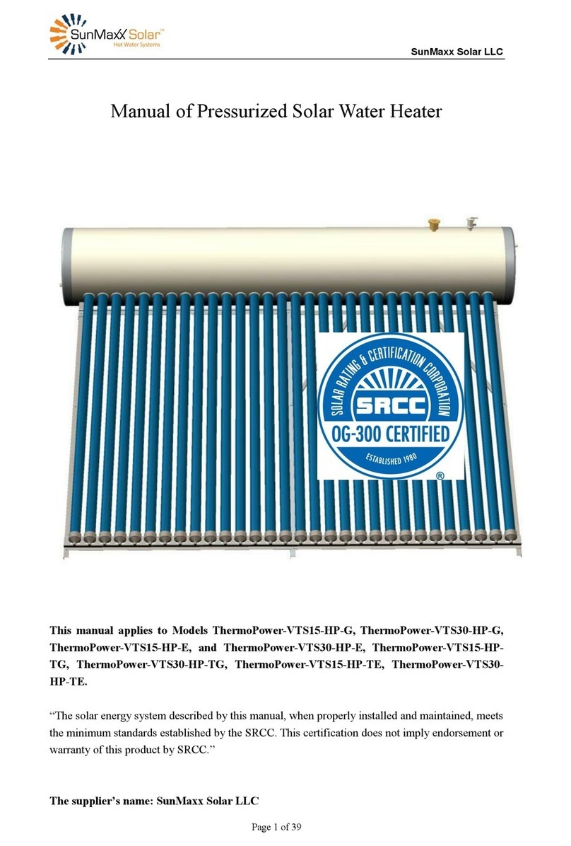
Manual of Pressurized Solar Water Heater
This manual applies to Model ThermoPower-VTS30HP.
“The solar energy system described by this manual, when properly installed and maintained, meets
the minimum standards established by the SRCC. This certification does not imply endorsement
or warranty of this product by SRCC.”
The supplier’s name: SunMaxx Solar tm.
Address: 56 Broome Corporate Parkway, Conklin, NY 13748 USA

56 Broome Corporate Parkway
Conklin, NY 13748 USA
P 877.786.6299 | F 877.786.0329
www.sunmaxxsolar.com
Page 2 of 47
Contents
IMPORTANT INFORMATION AND WARNINGS........................................................................3
SOLAR WATER HEATER PACK AND TRANSPORT ..................................................................4
1. Features of pressurized solar water heater ....................................................................................5
2. Structure of solar water heater ......................................................................................................6
3. Working principle..........................................................................................................................7
3.1. Principle of vacuum tube ...................................................................................................7
3.2. Working principle of solar water heater.............................................................................8
4. Technical data and product description.........................................................................................9
4.1 Technical data......................................................................................................................9
4.2 System Tolerance Information ..........................................................................................10
4.3 System start-up procedures...............................................................................................10
4.4 System pipe anti-freezing protections...............................................................................11
4.5 Specific notices.................................................................................................................12
5. Installation of solar water heater.................................................................................................14
5.1. Frame installation drawing...............................................................................................14
5.2. Water tank and vacuum tube assembly drawing ..............................................................15
5.3. Solar water heater assembly step .....................................................................................15
6. Pipeline installation.....................................................................................................................24
6.1 plumbing system schematic map.......................................................................................24
6.2 plumbing connections.......................................................................................................29
All the system labels will be packaged with the product when shipment and all of them were
made of weather proof material. Some of them must be attached to the valves with plastic or
wire tie after installation. If the label is lost or damaged for some reason, type a new one on
heavy paper stock and seal in clear plastic to make it water proof. ........................................31
6.3 Insulate the pipe................................................................................................................34
7. Commissioning the system .........................................................................................................37
8. Troubleshooting ..........................................................................................................................38
9. Maintenance requirements..........................................................................................................39
9.1. Cleaning...........................................................................................................................39
9.2. Leaves ..............................................................................................................................39
9.3. Broken tube......................................................................................................................39
10. Special conditional operation....................................................................................................40
11. Other important information .....................................................................................................41
12. Warranty Card...........................................................................................................................41
For you record:................................................................................................................................42
ANNEX 1........................................................................................................................................43
ANNEX 2 Notice Label..................................................................................................................46

56 Broome Corporate Parkway
Conklin, NY 13748 USA
P 877.786.6299 | F 877.786.0329
www.sunmaxxsolar.com
Page 3 of 47
IMPORTANT INFORMATION AND WARNINGS
Safety & Regulatory information
DO NOT operate this system before reading the manufacturers’instructions.
This appliance must be installed, commissioned and serviced by an authorized person
in accordance with all applicable local rules and regulations.
This appliance is not intended for use by persons (including children) with reduced
physical, sensory or mental capabilities, or lack of experience and knowledge, unless
they have been given supervision or instruction concerning use of the appliance by a
person responsible for their safety.
For continued safety of this appliance it must be installed, operated and maintained in
accordance with the manufacturers’ instructions.
Children should be supervised to ensure they DO NOT play with the appliance.
Prevent from burn injury, touching the heat pipes in the glass tubes is strictly
prohibited. The evacuated tubes are not allowed to be exposed under the sunshine
directly before installation.
Care should be taken not to touch the pipe work as it may be HOT! Plastic pipe is
NOT suited to the water temperature and pressure that may occur in the system.
DO NOT store chemicals or flammable materials neat the appliance.
NEVER use a flammables spray such as hair spray, lacquer, paint, etc. near this unit
as this may cause a fire.
The domestic solar water heating systems will reduce your energy bill and protect our
earth by cutting the carbon footprint. SRCC published the system performance at
different location of the United Stated. You can refer to the report or certificate for the
details of the energy saving.

56 Broome Corporate Parkway
Conklin, NY 13748 USA
P 877.786.6299 | F 877.786.0329
www.sunmaxxsolar.com
Page 4 of 47
SOLAR WATER HEATER PACK AND TRANSPORT
All ThermoPower-VTS30HP appliances (storage tank, evacuated tube, support base
and connection accessories), are delivered well packed to the customer.
The storage tank is placed between two round Styrofoam covers of 7 cm each, which
are tightened on the storage tank with stretch film. Then it is placed in a hard carton
pack, on which the indications of each model are displayed on the outside. The frame
and reflector are fixed beside the tank in the same box.
The evacuated tube with heat pipe and aluminum fin is packed with 4 plastic
protective elbows, attached on 4 different positions of the tube. One box can store 15
or 10 pics tube, and then packed in a wooden box.

56 Broome Corporate Parkway
Conklin, NY 13748 USA
P 877.786.6299 | F 877.786.0329
www.sunmaxxsolar.com
Page 5 of 47
1. Features of pressurized solar water heater
• High food grade stainless steel 304 2B. State of-the-art welding and achieves potable
water status.
• Through the 365 degree inner tube absorber, reflectors behind the tubes, the heat up
time is very fast from the time the sun rises on the east side of the tube until it goes
down on the west side –unlike flat plate, which has a high output during the sun’s
highest energy, around midday.
• Utilization all year round, even in cold, windy climates where freezing does not occur
below -2 degrees Celsius for short periods of time.
• Can operate with incoming water pressures of 0.4 MPa –no circulating pump or
controller necessary.
• The system will still function if some vacuum tubes lose their vacuum or are
accidentally damaged.
• All day tracking capabilities due to 360 degree absorber on inner tube.
• The diffuser reflector plate behind the glass tubes adds to the heat gain during blue
sunlight days.
• When consisting of more than one unit, can be installed using parallel and/or series
connections, increasing the hot water capacity supply.

56 Broome Corporate Parkway
Conklin, NY 13748 USA
P 877.786.6299 | F 877.786.0329
www.sunmaxxsolar.com
Page 6 of 47
2. Structure of solar water heater
Component description:
HEAT PIPES: An evacuated-tube collector contains several individual glass tubes,
each containing an aluminum fin and a heat pipe. The heat pipe transfers the heat
efficiently to the water in the tank.
WATER TANK: The storage tank is made of three layers: inner shell, intermediate
foam insulation and outer cladding. The shell is built to hold water pressure maximum
of 150psi. Shell material is corrosion-proof food-grade stainless steel. Foam insulation
thickness is decided to maintain the tank water temperature self-sustainable during
continuous unclear days in the coldest wintertime. Outer cladding is normally
galvanized sheet metal, providing a fine surface finish and a long-lasting life.
EVACUATED TUBES: Top quality double-walled tubes are chosen. There is an
aluminum or copper coated mirror on the inside surface of the inner glass wall. The
mirror well traps the thermal energy inside the tube. On the metal mirror layer, there is
selective absorption coating, which converts over 99% energy of visible and invisible
lights.

56 Broome Corporate Parkway
Conklin, NY 13748 USA
P 877.786.6299 | F 877.786.0329
www.sunmaxxsolar.com
Page 7 of 47
The outer glass wall acts as glazing, creating a vacuum space and protects the coating
against weather. On the inner surface of tube ends, a silver-colored getter material is
applied, which absorbs the remaining gases inside the tube hollow space. Deducting the
absorption and surface reflection of the outer wall of a tube, the overall efficiency of a
tube is over 92%.
REFLECTOR: Reflector is silver coated reflecting panel. The reflectors can improve
solar system thermal efficiency and reinforce the frame structure.
FRAMES: Frame is made of rustproof material. Aframe may have full-length rear legs,
suitable for flat surface installation, or, shortened rear legs, suitable for sloped surface
installation. Length of rear legs could be cut to fit at site.
3. Working principle
3.1. Principle of vacuum tube
The vacuum tube is composed of inner tube, outer tube, selective absorption layer,
vacuum space, inspiratory layer. The outer wall of the inner tube is the selective
absorption layer. The space between outer tube and inner tube is the vacuum space. At
the bottom of the outer tube, there is an inspiratory layer which can be used to absorb
the remnant air.

56 Broome Corporate Parkway
Conklin, NY 13748 USA
P 877.786.6299 | F 877.786.0329
www.sunmaxxsolar.com
Page 8 of 47
3.2. Working principle of solar water heater
The vacuum tubes absorb the solar energy, and aluminum fin pass the heat energy
to the heat pipe. The liquid medium in the heat pipe is heated by the heat energy, and
then turns into the gas medium. The gas medium flows up to the top of the heat pipe
and transfer the energy to the cold water in the tank, at the same time the gas medium
turns into the liquid one and flows down. The liquid medium keeps recycling and the
water in the tank will become hot.

56 Broome Corporate Parkway
Conklin, NY 13748 USA
P 877.786.6299 | F 877.786.0329
www.sunmaxxsolar.com
Page 9 of 47
Fig 3.1 Solar water heater working sketch map
4. Technical data and product description
4.1 Technical data
Model
ThermoPower-VTS30HP
Number of Tubes
30
Gross area
4.45m2
Tank Volumetric Capacity
300L
Weight Empty
90Kg
Fill weight
330Kg
Length of Tubes
1800mm
Outer tube diameter
Ø58mm
Tube thickness
1.6mm
Tube Thermal Expansion
3.3×10⁻⁶ m/m°C
Absorptive coating
Graded Al-N/Al
Absorbency
>92%(AM1.5)
Emittance
7%(100℃)

56 Broome Corporate Parkway
Conklin, NY 13748 USA
P 877.786.6299 | F 877.786.0329
www.sunmaxxsolar.com
Page 10 of 47
Vacuum
P<0.005Pa
Heat Loss
<0.8W/㎡
Insulation
Polyurethane,55mm
Stagnation Temperature
<220℃
Maximum working temperature
90℃
Maximum Working Pressure of all
circuits
0.6MPa
Working pressure
0.4MPa
Maximum wind and snow load
0.49kN/m²
Tilt Angle
45°
Inlet and Outlet
1/2inches
T&P Valve Port
1/2 inches
Frame
Aluminum Alloy
4.2 System Tolerance Information
Freeze tolerance limits are based upon an assumed set of environmental conditions.
Extended periods of cold weather, including ambient air temperatures above the
specified limit, may cause freezing in exposed parts of the system. It is the owner’s
responsibility to protect the system in accordance with the Supplier’s instructions if
the air temperature is anticipated to approach the specified freeze tolerance limit.
4.3 System start-up procedures
After the system installation, check there is no leakage in the system and follows the
following steps to start up the system.
Step 1: Connect Garden Pipe to Drain Valve V4, and keep V4 Open.
Step 2: Open the following valves: V0, V2, V4 and shut off the following valves: V1,
V3, and V5
Step 3: Keep the water running for 5 minutes to flash out the solder or stains after the
water from V4 is observed.
Step 4: Shut off V4 and Open V3, and the system is in normal operating status.

56 Broome Corporate Parkway
Conklin, NY 13748 USA
P 877.786.6299 | F 877.786.0329
www.sunmaxxsolar.com
Page 11 of 47
4.4 System pipe anti-freezing protections
This is a direct DHW system. The plumbing copper pipe needs anti-freezing
protection when the lowest temperature is below 23 Fahrenheit or -5 Celsius in the
coldest climate. The detail anti-freezing protection is described as follows.
The tables SRCC uses to evaluate the freeze protection provided by pipe insulation
indicate that 1.5 inches of insulation on a 0.75 inch type L copper pipe will protect the
pipe down to about 14F. It would be ok for the whole system if the entire pipe was
insulated well under this temperature condition.
It would be better to drain down the whole system if the temperature is lower than
14oF to avoid the connecting pipe freezing. The connecting pipe can be protected
against freeze damage.
In case of black out or power outage occurs during the cold weather when the
temperature is lower than 14 Fahrenheit or -10 Celsius, a system drain out procedure
must be followed as follows, and the existing Aux water heater must have adequate
capacity, listed and labeled by an accredited listing organization to continue provide
adequate hot water.
Step 1: Shut off V2 and V3 Solar Isolation valves to Isolate Solar System.
Step 2: Open V1 to using Aux hot water heater system, and bypass the solar water
system. Ensure the V0 is open.
Step 3: Connect Garden Pipe to both Drain Valve V4 and V5.
Step 4: Put the both Garden Pipes in the house drain dock or sinks.
Step 5: Open both V4 and V5 drain valves, until no more water comes out of either
pipes.
Step 6: Shut off both V4 and V5 drain valves.
When the electricity power is back to normal, follow the system start-up procedures to
set up the system to normal operation.

56 Broome Corporate Parkway
Conklin, NY 13748 USA
P 877.786.6299 | F 877.786.0329
www.sunmaxxsolar.com
Page 12 of 47
4.5 Specific notices
4.5.1 Aux Hot Water Heater
The system is not a replacement of the existing Aux Hot Water Heater. It is installed at
the upstream of the existing conventional hot water heater. The Aux Hot Water Heater
must be maintained as usual. The Aux water heater must have adequate capacity,
listed and labeled by an accredited listing organization. The Aux water heater should
have the proper built in insulation by the accredited organization. If the Aux Water
Heater doesn’t come with the insulation, it should be covered with a minimum R2.2
insulation with thickness of 1/4”. (GUIDE: 6.1.1.4)
4.5.1 Different metallic materials
To prevent galvanic corrosion, a dielectric union or coupling is recommended to
install in between the copper pipe and steel tank. (GUIDE: 6.1.1.10)
4.5.2 System Tank (GUIDE: 6.1.3.2)
The direct system comes with 63 gallons tank and no heat exchanger, hence no extra
tank is needed.
4.5.3 Heat Transfer Fluid (HTF) inside the heat pipe (GUIDE: 6.1.3.6 and 6.3.7)
The HTF inside the heat pipe is a small amount of pure water at a very low pressure.
The heat pipe, HTF are built as one unit, no refill is needed, and the water inside will
not be reduced.
No other fluid shall be used that would change the original classification of this
system. Unauthorized alterations to this system could result in a hazardous health
condition.
4.5.4 Temperature Sensor Wiring and System Monitoring (GUIDE: 6.1.5.5 and 6.4.1)
Connect each of the temperature sensors with the cold water pipe and hot water pipe
respectively. Put one-foot R4.4 insulation on both sensors. The sensor and pipe
intersection point should be in the middle of the one foot insulation.
To determine whether the solar system is working, observe the thermometer when the
hot water is being used in the house. The water returning from the collector on a
sunny day should be at least 10 Fahrenheit warmer than the water going up to the
collector. The temperature of the cold water and hot water is displayed on the monitor.
4.5.5 The insulation of the final 5 feet to the auxiliary water heater (GUIDE: 6.1.6.3)
The insulation of the final 5 feet to the auxiliary water heater shall be insulated with
R-0.46 K m2/W or greater insulation.

56 Broome Corporate Parkway
Conklin, NY 13748 USA
P 877.786.6299 | F 877.786.0329
www.sunmaxxsolar.com
Page 13 of 47
4.5.6 Public Traffic Statement (GUIDE: 6.3.17)
Components exposed to public traffic should be maintained below 140°F or
insulated/isolated to prevent any hazards to the public traffic.
4.5.7 Components accessibility (GUIDE: 6.4.6)
All components should be accessible for maintenance and servicing.
4.5.8 Installation and Maintenance Practices (GUIDE: 6.5.5 and 6.5.10)
Do not impair enclosure function. Do not allow vermin intrusion. Ensure to meet
applicable codes and national Roofing Contractors Assoc. practices. The entire system
should be checked by the installer once every two years.
Follow the specific codes and practices to penetrate the structural members for the
solar system.
4.5.9 Safe practices (GUIDE: 6.5.11)
Building materials adjacent to solar components are not exposed to elevated
temperatures.
4.5.10 System mounting (GUIDE: 6.5.12, 6.5.13, 6.5.14 and 6.5.19)
Allocate a place is not shaded during 10:00AM to 3:00PM, and keep the solar panel
facing south with 45 degrees of adjustment tolerance. The pitched degree of the panel
should be close to the latitude of the location.
All the piping should proper support according to the plumbing codes. These supports
must not compress the insulation.
Any structural member or fire rated assembly should not be reduced after penetration
during the installation. It will be up to the local code to dictate exactly how this is
done. The outdoor pipes should be insulated with R6.6 insulation with thickness at or
greater than 1 inch. The indoor pipes should be insulated with R2.6 with thickness at
least 1/4”.
4.5.11 Projected components need to be replaced
The glass vacuum tubes might need to be replaced after it is broken by the unexpected
hazards, such as hit by the hard material. Please contact to the installer to order the
parts and do the replacement. The battery of the temperature monitor needs to be
replaced when the battery is out. The battery can be purchased at store.

56 Broome Corporate Parkway
Conklin, NY 13748 USA
P 877.786.6299 | F 877.786.0329
www.sunmaxxsolar.com
Page 14 of 47
5. Installation of solar water heater
5.1. Frame installation drawing

56 Broome Corporate Parkway
Conklin, NY 13748 USA
P 877.786.6299 | F 877.786.0329
www.sunmaxxsolar.com
Page 15 of 47
5.2. Water tank and vacuum tube assembly drawing
5.3. Solar water heater assembly step
5.3.1 Installation of frame:
Firstly, open the packing case to check the fittings related with the frames and
their quantity. They include front and rear legs, assistant bars, cross bars, tank
brackets, tail stock track, tail stocks, reflectors, cousins as well as screw bag.
Fig 1
Fig 2

56 Broome Corporate Parkway
Conklin, NY 13748 USA
P 877.786.6299 | F 877.786.0329
www.sunmaxxsolar.com
Page 16 of 47
Step 1. Take the tail stock track out and
put it under the frame. Open the screw
bag, finding the bolts that match the
connecting holes to connect the tail
stock track with front legs.
Step 2. Take the reflectors out and connect
them with front legs by bolts and nuts.
Attention: the reflector near to the tail
stock track should not be installed now so
as to operate more easily in the installation
of the rear legs and assistant bars.
Fig 3
Fig 4
Step 3. Find the tank brackets and
connect them with rear legs. Attention:
The installation of the three tank
brackets is the key point; observe
carefully so as to avoid the faulted
installation.
Step 4. Take the rear side legs out and
connect them with the corresponding
connecting holes of the tank brackets by
bolts. Observe carefully how the rear side
legs are collected with the tank brackets.
Fig 5
Fig 6
Step 5. Connect the front legs with rear
legs by assistant bars, pay attention to
the length order of assistant bars. Take
Step 6. Take the cross bars out that are
used to fasten the rear legs, group them
together first. Connect the cross bars

56 Broome Corporate Parkway
Conklin, NY 13748 USA
P 877.786.6299 | F 877.786.0329
www.sunmaxxsolar.com
Page 17 of 47
the rear middle leg out and connect it
with the tank brackets. Attention: Put
two angle irons together as the rear
middle frame and then connect them
with the tank brackets. The assistant
bars are collected with the reflectors by
the same screw. Take the last rear leg out
and connect it with the tank brackets.
Then use the assistant bars to connect
the rear and front legs in the same way
mentioned above.
with the two adjacent rear legs.
The cross bars can fasten the rear legs
well for fear that the strong wind
destroys the frames.
Fig 7
Fig 8
Step 7. At last connect the cousins to the
corresponding front and rear legs.
Step 8. Turn the frame over and put it on
the ground at the installation angle
between the front legs and rear legs.

56 Broome Corporate Parkway
Conklin, NY 13748 USA
P 877.786.6299 | F 877.786.0329
www.sunmaxxsolar.com
Page 18 of 47
5.3.2 Installation of the tank:
Fig 1
Fig 2
Fig 3
Step 1. Screw off the nuts
from the connection bolts
of the water tank. Take the
water tank out. Put it on
the well-installed frames
slowly and lightly.
Attention that insert the
bolts of the water tank
into the corresponding
connecting holes of the
tank brackets.
Step 2. Install the
accessories and revolve
the small red cap of the
air vent on the top to
ventilate.
.
Step 3. Install the T.P
valve.
5.3.3 Installation of the heat pipe and vacuum tubes
Step 1. Firstly sheathe the anti-dust circles onto the vacuum tube.
Step 2. Take the adjustable tail stocks down.
Step 3. Pull the heat pipe out of the vacuum tube about 20 centimeters.
Step 4. Sheathe the white Teflon gasket into the heat pipe and put it onto the convex
of the copper circle.

56 Broome Corporate Parkway
Conklin, NY 13748 USA
P 877.786.6299 | F 877.786.0329
www.sunmaxxsolar.com
Page 19 of 47
Step 5. Put the heat pipes into the water tank slowly. Attention: If it is not easy and
convenient to do, we can adjust the angle between the water tank and the ground
properly.
Step 6. Connect the joint screw with the nuts inside the water tank and screw them
tightly by 22mm spanner. Please pay attention to the tightness extent, avoiding being
too loose to cause water leakage.
Step 7. Install all the heat pipes according to this method. Adjust the angle and the
inappropriate places, keeping them horizontally. Then charge water into the tank to
check if there is a leakage from the connections.
Step 8. Insert the vacuum tube into the anti-dust circle of water tank, and then install
the tail stocks that have been taken down. Attention: when inserting the vacuum
tubes, they cannot be revolved for fear that they destroy the heat pipes.

56 Broome Corporate Parkway
Conklin, NY 13748 USA
P 877.786.6299 | F 877.786.0329
www.sunmaxxsolar.com
Page 20 of 47
At last fasten all the screws.
5.3.4 Solar water heater installation and attention
This STEP requires you to locate your hot water heater. The collector should face
approximately South (plus or minus 20°). Use a declination value from a map or
declination table to determine the direction of true South from the compass reading.
The collector should be tilted at the latitude angle plus 15° for best winter operation
and latitude minus 15ofor best summer performance. Tilt at latitude for best year
round performance.
A good GPS will also provide accurate compass headings and your exact latitude. If
you do not have a compass or GPS, wait until solar noon and the shadow of a vertical
stick or surface will point due North. True South is 180° from true North. HINT:
MANY SOLAR SYSTEMS ARE PLACED AT THE ROOF SLOPE WHICH IS
LESS THAN LATITUDE MINUS 15°, BUT IS MORE AESTHETICALLY
PLEASING, WITH ONLY A SMALL 10% PENALTY IN ANNUAL
PERFORMANCE.
The latitude of your location can be found on the Internet or in your local paper. The
latitudes of some selected U.S. cities are presented in Table 5-1 for reference. (HINT:
Look at other solar collectors in your area, see how they are oriented to South and
elevated for latitude) .The report includes a solar sitting template to show the effects
of shadowing from trees or nearby buildings, declination map and other useful
information about system sitting.
Table of contents
Other SunMaxx Solar Water Heater manuals
Popular Water Heater manuals by other brands

ACV
ACV BNE 1 Installation, operating and maintenance instructions

Worcester
Worcester WR 325 BF Installation and servicing instructions

Santon
Santon AH7/2.2 Installation and user instructions

Rotex
Rotex EHS/500/5 manual

Kenmore
Kenmore POWER MISER 9 owner's manual

Amtrol
Amtrol T-5 Installation & operation instructions