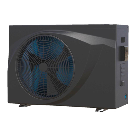
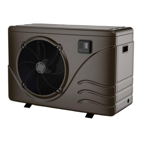
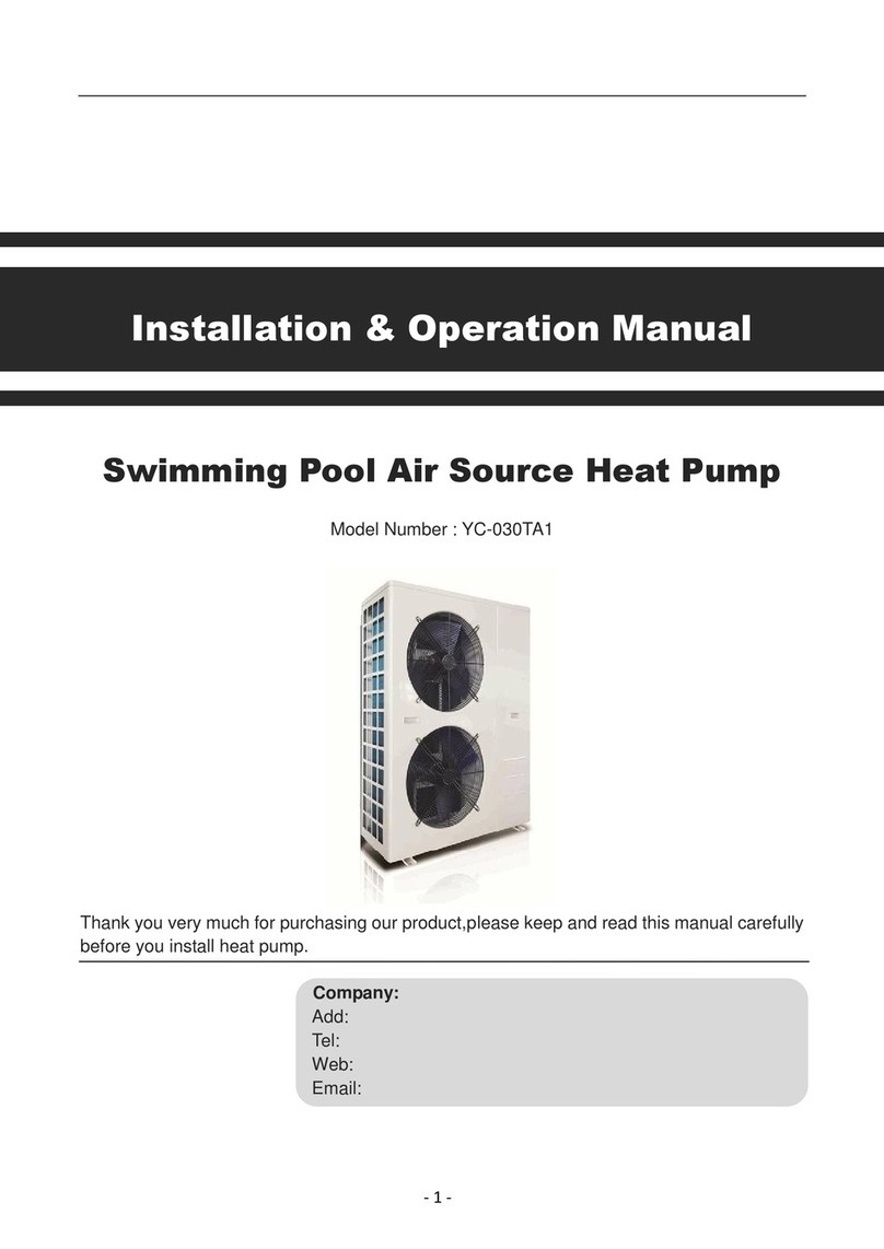
Sunrain YC-050TA1 User manual

Installation & Operation Manual
Swimming Pool Heat Pump
Commercial Type
Model Number : YC-050TA1
Thank you very much for purchasing our product, please keep and read this manual carefully before you install heat
pump.
Packing List

- 2 -
No.
Name
Qty.
Photos
1
Installation & Operation Manual
1
2
Wire-controller
1
3
Heat exchanger connector
2
4
Wire-controller signal wire
1
5
Heat Pump Unit
1

- 3 -
Please keep installation manual properly, and read it carefully before using.
The unit must be installed by professional personnel, and install it based on this manual as
possible.
Special reminding: if the unit would be installed where is vulnerable to lightning stroke, lightning
protection measurements must be carried out.
Special reminding: The unit is not suitable for using in the Winter (< -7 °C), when the unit leave
unused in Winter, the water reserved in the pipe network system must be drained.
Content
1. Accessories Description.......................................................................................4
2. Attention for safety.................................................................................................4
3. Heat pump unit working principle......................................................................6
4. Installation of the unit............................................................................................7
5. Installation of the pipeline..................................................................................10
6. Installation of optional accessories................................................................ 12
7. Installation of electric devices.......................................................................... 13
8. Instruction of operation...................................................................................... 17
9. Adjusting and Initial operation......................................................................... 26
10. Operation and maintenance............................................................................ 27
11. Fault analysis and elimination method........................................................29
12. Technical parameter.......................................................................................... 30

- 4 -
1. Accessories Description
Each unit produced by our factory with the following accessories:
For function you need to purchase at least the following parts for each unit:
No.
Name
Qty.
use
1
Water circulation pump
Drive the water cycle
2
Swimming pool filter system
Protect the heat pump heat exchanger and pipes
3
Water pipe and valves
Connect the equipment and make circulation
NOTE
The types and quantity of the water pump, filters, pipes and water tank, refer to the real project design.
We do not suggest to install auxiliary electric heaters in the system, if must install auxiliary electric
heaters, should install the electric heaters by the specialized persons, and our company has no
responsibility for all the problem cause by the auxiliary electric heater.
2. Attention for safety
Range of application:
1.Power supply: 380V/3N~50Hz.
2.Environment temperature: -7°C〜43°C :
3.Working water temperature: Min. inlet water temperature 8°C, Max. outlet water
temperature 40°C. If the system is always used beyond the available water range,
please contact with the local agent.
●The installation shall be done by the professional persons, to prevent leaking, electric shock, or fire
disaster.
●Confirm the ground connection, if the ground connection is not correctly done, it may cause electric
shock.
No.
Name
Qty.
Use
1
Installation & Operation Manual
1 PC
Guide users to install the system
2
Wire controller
1 PC
Used for the man-machine operation interface
3
Wire controller connecting cable
1 PC
Connect wired controller to heat pump unit
4
Heat pump unit
1 SET
For heating water

- 5 -
●When install the heat pump in a narrow space (equipment room), must keep well ventilated.
●Don't put finger or sticker into the air inlet or air outlet. Because the internal rotor high-speed operation
may cause injury.
●When an exception happens (burning smell), turn off the manual power switch immediately, stop
operating, and contact with after-sale service department. If continue the abnormal operation, it may
cause electric shock or fire disaster.
●When the unit needs to be removed or re-installed, please entrust after-sale service department and
specialized personnel to do it. If the installation is not well done, it may cause unit operation failure,
electric shock, fire, hurt, leaking, etc.
●Must not be unauthorized reformed, otherwise it may cause electric shock or fire.
●When needs to be repaired, please entrust after-sale service department or a specialized personnel to
implement. If improper repaired, it may cause unit operation failure, electric shock, fire, hurt, leaking, etc.
●Can not install the unit in combustible gas easy-leaking places, once the combustible gas leaks around
the unit, it may cause a fire.
●Confirm if the installation base is strong enough, if it is not strong and has been used for a long time, it
may cause falling and injuries.
●Confirm if leakage protection switch is installed, if don't install a leakage protection switch, may cause
electric shock or fire.
●When cleaning the unit, the operation should be stopped, and power switch should be turned off.

- 6 -
3. Heat pump unit working principle
3.1 Heat pump working process
● First, the low pressure and superheated gas in the evaporator is inhaled into the compressor then
becomes the high temperature and high pressure overheated vapour.
● Second, the overheated vapour is exhausted into the condenser and exchange the heat with the water,
then the refrigerant is condensed and becomes the saturated or over cooling high pressure and high
temperature refrigerant liquid. The water is heated up by heat pump when absorbing the heat energy
which released by the refrigerant.
● Third, the refrigerant liquid releases the pressure by passing the expansion valve, then becomes the
low temperature and low pressure liquid.
● Fourth, the refrigerant liquid flows into the evaporator and absorb the energy from the air, then is
vaporized and became the low pressure and overheated vapour. The refrigerant working repeatedly as
described above, then the water which flows through the condenser is heated up constantly, the
temperature rise and can get the hot water.
3.2 Air source heat pump working principle
4 way valve
Water inlet
Water Outlet
Condenser
Gas-liquid
separator
Compressor
Filter
Expansion valve
Filter
Ev apor ator
Fan un it
Figure 1
Qc(Heat energy get) =Qa(Compressor consumption) +Qb(Heat energy absorbed from ambient environment)

- 7 -
4. Installation of the unit
4.1 Installation attention
● Avoid installations in such locations with mineral oil.
● Avoid installation in locations where air contains salt or other corrosive gas.
● Avoid installation in locations with serious power supply voltage fluctuation.
● Avoid installation in an unstable place, such as car or cabin
● Avoid installation near flammable items.
● Avoid installation in locations with strong electromagnetic wave.
● Avoid installation in locations with special harsh environmental conditions.
4.2 Installation check
● Check the model, number, name etc, avoid incorrect installation.
● Make sure enough space for installation and maintenance.
● Make sure barrier-free for air inlet and outlet, also dry ventilated place.
● Make sure the bearing surface can meet the requirement and avoid shocks.
● The power supply and its capacity, wire diameter choice should be in accordance with the electrical
installation requirements.
● Electrical installation must comply with the relevant technical standards of electrical equipment, and
electrical insulation work must be done.
● The unit must be power on for at least eight hours before running and debugging.

- 8 -
4.3 Installation space
Keep the following indicated space for operation and maintenance first before installation
Figure 3 Installation space
>1200
>1200
Figure2 The distance to top barrier
>2000
>500
>600
>500
>1200
>500
>500
>600
>1200
Unit: mm
Unit: mm
Unit: mm

- 9 -
4.4 Heat pump unit size
YC-050TA1
Figure 4 Size
Size (mm)
Model No.
L
W
H
YC-050TA1
1410
748
1000
4.5 Reserve the installation base for the heat pump
Please refer to Figure 5.
A n c h o r b o lt
Drainage tray
Heat Pump
Installation base
Concrete
Anchor bolt
Screw nut/washer
Shock absorb
Heat Pump
Drainage tray
Figure 5 Reserved installation base
4.6 Hoisting attention
● Please use four or more soft lifting belts to move the sets Figure 6.
● Please use protective plate on the surface of the sets when moving, to avoid scratch and deformation.
● Recheck whether the foundation is correct before hoisting the unit.
● The heat pump will produce condensation water,please consider the drainage channel when make the

- 10 -
installation base.
● Please put shock absorb on base surface.
Figure 6 Hoisting diagram
5. Installation of the pipeline
5.1 Attention
● Prevent air, dust and other sundries from going into the water pipes.
● Fix the whole system before install the water pipes.
● Water inlet and outlet pipes shall be protected by the insulation layer.
● Stable water velocity shall be ensured, so that excessive throttling can be avoid.
● When moving, water inlet and outlet pipe shall not be used for hanging, only the holes on the beam of
the base can be used, please refer to Figure 9
● When connect the water inlet and outlet pipes, two pipe wrenches shall be used to control the two parts
of the pipes, and ensure the water inlet and outlet pipes not turning around, please refer to the Figure 7
● Pipeline anti-freezing in case the environmental temperature drops to 3°C.
Figure 7

- 11 -
5.2 Instruction
5.2.1 Marginal data
5.2.2 Pipeline installation diagram
Figure 8 Diagram I(Single unit for reference)
Figure 9 Diagram II(Multiple units for reference)
● The one-way valve is suggested for each unit, to prevent the water back flow.
● The system can be combined with multiple units, but should be controlled by each unit independently.

- 12 -
● Regarding the installation of backup pump, maintenance valve and temperature measure point, please
consider it yourself.
● All pipes and valves of the unit need the heat preservation.
● The reference diagram used non-pressure water tank, the system also can be pressurized system, use
the pressurized water tank.
5.2.3 Selection of the water pipes
Model No.
Inlet
Outlet
YC-050TA1
63 mm
63 mm
● The pipe press and flow rate should be calculated before the diameter selection.
● The hydraulic calculation should be made after the selection of pipe diameter, if the resistance is more
than pump head, then need to choose a more power pump, or choose a bigger pipe.
6. Installation of optional accessories
6.1 Selection of the water pump
● The circulation pump is necessary for the system operation, the power port is prepared for the pump
inside the unit.
NOTE
Please check the Electric Diagram which located inside of the unit
● The head of circulation pump = height difference between water level and main unit + total pipelines
resistance (determined by the hydraulic calculation) + pressure loss of main unit (see the nameplate on
heat pump ).
NOTE
When multi paralleled, the water pump head is subject to the worst working condition loop.
6.2 Selection of the flow switch
● The selection of the flow switch is based on the actual system, the target flow switch is recommended.
Temperature of fluid: 0-120 °C , max working pressure 13.5 bar.
● The flow switch can be installed on the horizontal pipeline or the vertical pipeline which the fluid flow
direction is upward, but should not be installed on the vertical pipeline which the fluid flow direction is
downward.
● The flow switch must be installed on a straight pipeline, there must be more than five times the length of
the pipe diameter at its two sides. And, the direction of fluid must follow the arrow on the controller. The
terminal block should be in an easy operation position, (Figure 10)
● The pannier is absolutely forbid to touch the flow switch floor, or the switch will be deformed and invalid,
(Figure 11)
● Please be sure that the model of target sheet is determined by the system rated flow, diameter of outlet

- 13 -
pipe and the adjustable range of the target(see the user manual). And the target sheet can not contact the
in-wall of pipe or other throttlers in pipe, or will cause the switch can not reset.
A
5A 5A
Figure 10
Figure 11
7. Installation of electric devices
7.1 Electrical wiring
● The unit should use a dedicated power supply, power supply voltage with rated voltage.
● Unit power supply circuit must be ground, power supply wire and external grounding reliable connection,
and the external grounding is effective.
● Wiring must be constructed by the professional installation technicians in accordance with the circuit
diagram.
● Power line and signal line layout should be neat, reasonable, can not interfere with each other, but not
with the connecting pipe and the valve body contact.
● If the unit is not matching the power line, please supply specifications refer to provisions, wires
connecting is not allowed.
● After all wiring construction is completed, please check it before switch on the power supply carefully.
Figure 12
Screw out the bolt and
open the panel which with
the danger label, will find

- 14 -
NOTE:
Here only for signal control never drive
it directly.
Power In
380V/50Hz/3phases
Figure 13 Power cable terminal
7.2 Electrical Wiring Specification
Model No.
Electrical Wiring Specification
YC-050TA1
3*6mm²+2*4mm²
7.3 Circulation pump installation
The heat pump only provide the signal for circulation pump, must use an a.c. Contactor to
connect the circulation pump.
Figure 14

- 15 -
Figure 15
7.4 Wire controller connection
Figure 16

- 16 -
7.5 Electric wiring diagram
Figure 17

- 17 -
8. Instruction of operation
8.1 Control system specifications
8.1.1 Operating condition
● Voltage:100V-265V, 50/60Hz
● Ambient temperature for operation: -30~+60℃
● Temperature accuracy: ±1℃
8.1.2 Main function
● Display the storage tank temperature, setting temperature and also check the coil temperature,
ambient temperature and exhaust temperature etc.
● Power cut memory function.
● When power cut, the clock will still work.
● Timing on/off.
● Automatic defrosting.
● Forced to defrost.
● Large LCD display.
● Has perfect protection function.
● The error code display and query
● Key-Lock Function
● Anti-freezing function
● When there is no remote controller or remote controller is broken, the system can recognize it,
and control the heat pump to run automatically.
8.1.3 Wire controller and Main control panel size
Wire controller size

- 18 -
Main control panel (PCB) size
8.1.4 Dial switch
Online unit address
setting
Dial1
Dial 2
Dial 3
Dial 4
Unit
OFF
OFF
OFF
OFF
Master unit
ON
OFF
OFF
OFF
Slave unit 1
OFF
ON
OFF
OFF
Slave unit 2
ON
ON
OFF
OFF
Slave unit 3
OFF
OFF
ON
OFF
Slave unit 4
ON
OFF
ON
OFF
Slave unit 5
OFF
ON
ON
OFF
Slave unit 6
ON
ON
ON
OFF
Slave unit 7
OFF
OFF
OFF
ON
Slave unit 8
Others
Dial 5
Dial 6
Dial 7
Dial 8
Result
OFF
Single phase
ON
Three phases

- 19 -
8.2 Remote controller and operation
8.2.1 Appearance and button of remote controller
Appearance
Symbol description
Symbol
Status
Description
Constantly bright
Heating mode
Extinguished
Cooling mode
Constantly bright
Heat pump is OFF
Extinguished
Heat pump is ON
Constantly bright
Alarm
Constantly bright
Defrosting
Flashing
Defrosting delay
Flashing
Refrigerant recovery
Constantly bright
Anti freezing
Constantly bright
Fast heating
Flashing
Fast heating delay
Constantly bright
Maintenance mode
Constantly bright
Compressor is ON
Flashing
Compressor delay
Constantly bright
Fan motor is ON
Constantly bright
Water tank temperature
Constantly bright
Temperature setting value
Constantly bright
Water inlet temperature
Constantly bright
Water outlet temperature
Constantly bright
Degree centigrade
Display
In timing mode
Flashing
In timer setting status

- 20 -
Display
In timing ON period
Display
In timing OFF period
88 88
Display
Display water temperature, temperature setting
value, error code
88:88
Display
Display the time
Display
Circulation pump is ON
Flashing
Turn on circulation pump by manual
Display
Water feeding valve is ON
Display
Water return valve is ON
Display
Low water level
Display
Middle water level
Display
High water level
Button description
No.
Name
Symbol
Description
1
ON/OFF
button
1.Press the button for 1 second, turn on/off the heat
pump
2.Exit the status query
3.Exit setting status
2
Up
button
1.Set the water temperature
2.Press the button for 3 seconds, enter into query
interface
3.In query status, page up
4.Set the parameter value
3
Down button
1. Set the water temperature
2. Press the button for 3 seconds, enter into
maintenance status
3. In maintenance status, page down
4. Set the parameter value
4
Time
button
1. In the main interface, press the button enter into
time setting, press again, switch to hour or minute
setting.
2. In the main interface, press the button for 3
seconds,
Enable the timer (in the meantime enter into timer
setting interface) or turn off the timer.
5
Mode
button
1. In the main interface, press the button for 5
seconds enter into parameter setting interface.
6
Function
button
1.When heat pump is OFF, and the current model is
heating&cooling heat pump, then press the button
can switch the operation mode between heating
and cooling
2.In the main interface, press the button for 3
seconds,query the on-line models and set the
operation mode.
7
Combination
button
+
When heat pump is ON, press these two buttons for 3
seconds, turn on/off the heating element forced
Table of contents
Other Sunrain Heat Pump manuals
Popular Heat Pump manuals by other brands

Trane
Trane 4TWR4 Use and care

Bitzer
Bitzer KB-200-1 operating instructions

Daikin
Daikin ETVH12S18EA6V Operation manual

Carrier
Carrier 30XW Installation, operation and maintenance instructions

Carrier
Carrier 38AUQA/B07 Installation and service instructions

Gebwell
Gebwell Qi Series Installation, operation and maintenance manual

Alpine
Alpine RP14AC Series Installation and maintenance instructions

Panasonic
Panasonic Aquarea WH-SXC12H6E5 Service manual

Carrier
Carrier 38UQZ016 Installation, operation and maintenance instructions

Carrier
Carrier 38YCC Series Product data

Aquacal
Aquacal AUTOPILOT 110 quick start guide

Riello
Riello NexSirius Instructions for the installer and the technical service centre