Sunsolar Energy Technologies SQ-2212 User manual

Model # SQ-2212
SPACE SAVER
INSTALLATION & OPERATION
MANUAL
Read all the instructions before installing your solar heating system.

2
How does a solar heating system work?
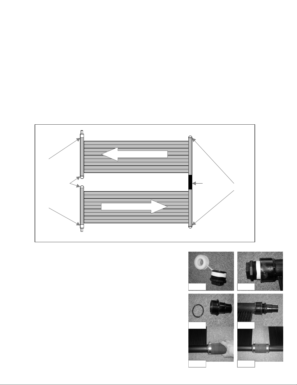
1. Connect your existing pool pump to the solar panel. Your pool pump
sends cold water to the solar panel.
2. The sun heats the water in the solar panel.
3. Warm water is then returned to your swimming pool.
How well does solar heating work?
A solar heating system if sized and installed properly will raise your pool water
temperature up to 100F / 60C and extend your swimming season. In order to maximize
the heat, the solar panel must be exposed to sunlight as long as possible. On rainy
days and at night the solar panel must be turned off so your pool water doesn't cool.
You can purchase an optional diverter kit to accomplish this. On cloudy days, the solar
panel won't work as well. It is recommended to use a solar blanket or a Liquid Solar
Blanket. This will help maintain the heat generated by the solar panel in your pool.
Is a special pump required?
If your panel is on the ground beside your pool, you can use your existing pool pump as long as it is in good working
condition. A 1HP pump will handle a panel placed up to 9 meters (30 ft)away from your pool and one story up.
Where can the solar panel be placed?
The solar panel can be placed on the ground.
Avoid placing in high traffic areas, as it is not
recommended to walk on the solar panel. The solar
panel can also be mounted on a rack or a roof. When
mounted, the panel should preferably be facing south
and be inclined at a 300 to 450degree angle. Don't
face the panel North, because it will not heat. A
mounting kit (part#SQ-RMK5) is required for placing
the solar panel on a rack or roof.
How many panels do I need?
Above-Ground
Round Pool
Above-Ground
Oval Pool
No. of Systems In-Ground Pool No. of Systems
Up to 15' Up to 12'x20' 1 Up to 15' x 30' 4
18' to 21' 12'x 24' to 12' x 28' 2Up to 16' x 36' 6
24' 16' x 25' 3Up to 20' x 40' 8
27' 16'x 32' to 18' x 34' 4
# of Panels is the minimum recommended.
More panels will give you more heat, faster.
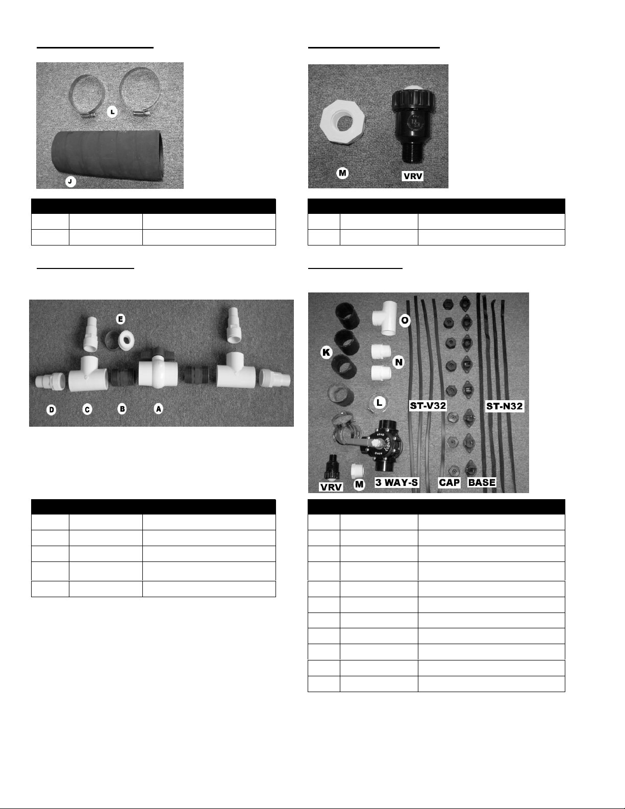
Box Contents:

3
Qty Part # Description Qty Part # Description
2 SK-1212 SunQuest solar panel 2ft x 12ft 2 SK-FTG-D Threaded combination hose adapter
2 SK-FTG-I "O" rings
4 SK-FTG-F Threaded cap
1 SK-FTG-J Rubber hose 7.5"
2 SK-FTG-L Metal collar (Hose clamp)
1 SK-FTG-E Roll of Teflon tape
Optional parts
Roof Mounting Kit (SQ-RMK5) High Wind Roof Mounting Kit (SQ-HWK)
1 - SQ-RMK5 per SQ-2212 system is required for Roof For high wind areas, to be used in addition to the roof mounting
or Rack installation kit (SQ-RMK5). 1 - SQ-HWK per SQ-2212 system is required
plus one extra.
Qty Part # Description Qty Part # Description
5 SK-RMK-ST-M Coated metal strap 2 SK-RMK-BASE Mounting base
15 BOLT-Z Lag bolt 2" 2 SK-RMK-CAP Mounting Cap
1 SK-RMK-ST-N32 Nylon strap 32"
1 SK-RMK-ST-V32 Vinyl strap 32"
4 BOLT-Z Lag bolt 2"
Optional parts (cont.)

4
Add-on Kit (SQ-ADDON) Vaccum relief Kit (SQ-VRK)
1 SQ-ADDON required per SQ-2212 system added Facilitates drainage for winterizing roof mounted systems
Qty Part # Description Qty Part # Description
1 SK-FTG-J Rubber hose 7.5" 1 SK-VRV Vacuum Relief Valve
2 SK-FTG-L Metal collar (Hose clamp) 1 SK-FTG-M Reducer Adapter 1.5" to 0.75"
Diverter Kit (SQ-DK) System Kit (SQ-SK)
Used to turn your system ON & OFF Everything needed to connect 3 SQ-2212 systems
Includes add-on kits, vacuum relief kit, high wind kits & diverter kit
Qty Part # Description Qty Part # Description
1 SK-FTG-A Threaded 2 way valve 4 SK-FTG-K Rubber hose 3.75"
2 SK-FTG-B Threaded nipple 8 SK-FTG-L Metal collar (Hose clamp)
2 SK-FTG-C Threaded tee 1 SK-VRV Vacuum Relief Valve
4 SK-FTG-D Threaded combination hose
adapter 1 SK-FTG-M Reducer Adapter 1.5" to 0.75"
1 SK-FTG-E Roll of Teflon tape 2 SK-FTG-N PVC Adapter
4 SK-RMK-ST-N32 Nylon strap 32"
4 SK-RMK-ST-V32 Vinyl strap 32"
8 SK-RMK-BASE Mounting base
8 SK-RMK-CAP Mounting Cap
1 VALVE-3WAY-S 3 Way Diverter Valve
1 SK-FTG-O PVC Tee
INSTALLATION

5
Additional parts required
•Flexible pool hose or rigid PVC pipe. Length dependent on distance from pool pump to solar panels.
•Metal collars (Hose clamps) - Quantity dependant on installation.
•For rack or roof placement a mounting kit (part # SQ-RMK5) is required
Tools required
•Flat head screwdriver.
•For rack or roof placement: a utility knife, a power drill and silicone sealant.
PANEL ASSEMBLY
1. Choose placement for your solar panel(s). Make sure that it will be in the sun for most of the day. The area should be
clear of sharp objects.
2. Take the panel out of the box, remove the strap from panel and let the panel sit in the sun for approximately 30
minutes so it will become flexible.
3. a) Installation: one system on ground.
Diagram Step 3a
•Apply Teflon tape to threads of all 4 caps (SK-FTG-F )
See Fig 3a-1
•Thread all 4 caps into the panels as per Diagram Step 3a.
Do not over tighten. See Fig 3a-2
•Put "O" rings (SK-FTG-I ) on both combination adapters (SK-
FTG-D) See Fig 3a-3
•Thread both combination adapters into the panels as per
Diagram Step 3a. Do not over tighten. See Fig 3a-4
•Push the rubber hose (SK-FTG-J ) over the panel header as per
Diagram Step 3a. Slide a metal collar (SK-FTG-L) onto the
rubber hose. Place metal collar 1/4" from edge and tighten collar
with screwdriver. See Fig 3a-5.
•Slide another metal collar onto the rubber hose. Connect the 2
panels together by pushing the rubber hose over the second
panel header. Tighten metal collar to secure assembly.
See Fig 3a-6
3 b) Installation: one system on rack or roof. (Vertical only)
Combination Adapter
Cap
Cap
Rubber hose
7.5"
Fig 3a-1 Fig 3a-2
Fig 3a-3 Fig 3a-4
Fig 3a-5 Fig 3a-6
Inlet
Outlet

6
1 - Mounting kit (part # SQ-RMK5) is required
Diagram Step 3b
•Using a utility knife or a hand saw, cut rubber hose (SK-FTG-J) in half. Make sure
you cut it as straight as possible. See Fig 3b-1. You should now have two rubbers
3 ¾" long.
•Apply Teflon on two of the caps (SK-FTG-F). See Fig 3a-1.You only need 2 of the 4
caps for this type of installation.
•Thread the 2 caps into the panels as per Diagram Step 3b. Do not over tighten.
See Fig 3a-2
•Put "O" rings (SK-FTG-I) on both combination adapters (SK-FTG-D). See Fig 3a-3
•Thread both combination adapters into the panels as per Diagram Step 3b.
Do not over tighten. See Fig 3a-4
•Push the rubber hose you cut in half previously over the panel header as per Diagram
Step 3b. Slide a metal collar (SK-FTG-L) onto the rubber hose. Place metal collar 1/4"
from edge and tighten collar with screwdriver. See Fig 3a-5. Repeat for other end of panel.
•Slide another metal collar onto the rubber hose. Connect the 2 panels together by pushing
the rubber hose over the second panel header. Tighten metal collar to secure assembly.
See Fig 3a-6. Repeat for other end of panel.
•Install mounting kits as per instructions included with them. Panels must be installed with a slight
slope (minimum 1 inch per 10 feet) toward the inlet. This will allow the panel to drain properly.
Note: The inlet must always be at the lower end of the panel and the outlet at the higher end of the panel.
3. c) Installation: two systems on ground.
Combination Adapter
Cap
Cap
Rubber hose
3.75"
Combination Adapter
Fig 3b-1
Inlet
Outlet
A Minimum of 1 inch fall per 10 feet

7
Add-on kit (part # SQ-ADDON) is required.
Diagram Step 3c
•Apply Teflon tape to threads of all the caps (SK-FTG-F) See Fig 3a-1
•Thread all the caps into the panels as per Diagram Step 3c. Do not over tighten. See Fig 3a-2
•Put "O" rings (SK-FTG-I) on two combination adapters (SK-FTG-D) See Fig 3a-3. You will only need
2 combination adapters for this type of installation.
•Thread both combination adapters into the panels as per diagram Step 3c. Do not over tighten. See Fig 3a-4
•Push the rubber hose (SK-FTG-J) over the panel header as per diagram Step 3c. Slide a metal collar
(SK-FTG-L) onto the rubber hose. Place metal collar 1/4" from edge and tighten collar with screwdriver.
See Fig 3a-5. Repeat for 2nd system.
•Slide another metal collar onto the rubber hose. Connect the 2 panels together by pushing the rubber hose
over the second panel header. Tighten metal collar to secure assembly. See Fig 3a-6. Repeat for 2nd system.
•Install Add-on kit (SQ-ADDON) between two sets of panels (sold separately)
Note: A maximum of 6 2ft panels (3 systems) may be plumbed in series
3 d) Installation: two systems on rack or roof. (Vertical only)
Combination Adapter
Cap
Cap
Rubber hose
7.5"
Combination Adapter
Cap
Cap
Rubber hose
7.5"
Rubber hose
7.5"
(Add-on kit)
Inlet
Outlet

8
2 Mounting kit (part # SQ-RMK5) are required.
1 System kit (part # SQ-SK) is required.
Diagram Step 3d
•Using a utility knife cut rubber hose (SK-FTG-J) from each system in half. Make
sure you cut them as straight as possible. See Fig 3b-1. You should now have
rubbers that are 3 ¾" long.
•Apply Teflon on one of the caps (SK-FTG-F). See Fig 3a-1.You only need 1 cap
for this type of installation.
•Thread the cap into the panels as per Diagram Step 3d. Do not over tighten.
See Fig 3a-2
•If you are using flexible piping to connect panels to your pump then Put "O" rings
(SK-FTG-I) on both combination adapters (SK-FTG-D) See Fig 3a-3. Thread both
combination adapters into the panels as per Diagram Step 3d. Do not over tighten.
See Fig 3a-4
OR
If you are using rigid piping to connect panels to your pump then apply Teflon on
both PVC adapters (SK-FTG-N). See Fig 3d-1. Thread both adapters into the
panels as per Diagram Step 3d. Do not over tighten. See Fig 3d-2.
•Apply Teflon on reducer adapter (SK-FTG-M). Thread reducer adapter into the
panel as per diagram Step 3d. Do not over tighten. See Fig 3d-3.
•Apply Teflon on vacuum relief valve (SK-VRV). Thread vacuum relief valve into
the reducer adapter. Do not over tighten. See Fig 3d-3.
Note: The vacuum valve assembly must be installed at the top of the panels as per diagram Step 3d.
3 d) Cont.
Vacuum Valve
Combination Adapter
Or PVC adapter
Outlet
Combination Adapter
Or PVC adapter
Cap
Rubber hose
3.75"
Inlet
Fig 3d-1
Fig 3d-3
A Minimum of 1 inch fall per 10 feet
Fig 3d-2
Rubber hose
3.75"

9
•Push the rubber hose you cut in half previously over the panel header as per diagram Step 3d. Slide a metal
collar (SK-FTG-L) onto the rubber hose. Place metal collar 1/4" from edge and tighten collar with screwdriver.
See Fig 3a-5. Repeat for other end of panel.
•Slide another metal collar onto the rubber hose. Connect the 2 panels together by pushing the rubber hose
over the second panel header. Tighten metal collar to secure assembly. See Fig 3a-6. Repeat for other end of
panel.
•Repeat previous 2 steps for other system.
•You should now have two sets of connected panels. You need to use rubbers from the system kit
(SK-FTG-K) to connect the two set together as per Diagram Step3d.
•Install mounting kits as per instructions included with them. Panels must be installed with a slight
slope (minimum 1 inch per 10 feet) toward the inlet. This will allow the panel to drain properly.
Note: The inlet must always be at the lower end of the panel and the outlet at the higher end of the panel.
Note: A maximum of 12 2ft panels (6 systems) may be plumbed in parallel
•For high wind areas you can install the Nylon straps and Vinyl straps from System Kit.
Mark a spot 6" to the top of the outlet. Mark spots 6" to the top of every second
rubber hose that are on the same side as the outlet. Mark a spot 6" to the top of the
vacuum relief valve. See Fig 3d-4. Place mounting base (SK-RMK-BASE) on these spots.
Drill pilot holes, apply silicone roof sealant and screw mounting base into roof. See Fig 3d-5.
Wrap a Nylon strap (SK-RMK-ST-N32) around the panel header (see Fig 3d-7) or
around rubber hose (see Fig 3d-6). Lay both ends of strap in the mounting base and
pull tight. See Fig 3d-8. Screw on mounting cap (SK-RMK-CAP). See Fig 3d-9.
Repeat process on the inlet side (bottom) of the panels but using the Vinyl straps
(SK-RMK-ST-V32) instead.
CONNECTING TO POOL
Fig 3d-6
Fig 3d-5
Fig 3d-4
Fig 3d-7 Fig 3d-8 Fig 3d-9

10
System with no diverter
Diagram C-1
1. Turn off your pool pump. Block the inlet and outlet of your pool so that the water won't empty
when you are connecting your panel(s).
2. Remove the hose from the pool inlet ( hose between the filter and the pool ) and connect the
hose to the panel inlet. If hose is too short, you need to purchase a new one. Make sure
you purchase the appropriate size that is compatible with your existing pool equipment.
For 11/4" hose, it will only slide over the small end of the combination adapter. See Fig C1-1.
For 11/2" hose, it will slide all the way to flange of combination adapter. See Fig C1-2. Place
metal collar 1/4" from edge and tighten collar with screwdriver. See Diagram C-1.
3. Connect another hose (not supplied) from the panel outlet to the pool inlet. See Diagram C-1.
4. Make sure that your hoses are all connected the correct way and that all the collars have been
tightened. Unblock the inlet and outlet of your pool.
5. Turn on your pool pump. Check for any leaks. If any of the threaded fittings leak, remove the
fitting and apply more Teflon. If any of the hoses leak at the connection, loosen the collar and
push the hose over the fitting and re-tighten the metal collar. You will see air bubbles coming
from the pool inlet. This is normal and will stop once the air inside the panels has been purged.
Note: Without a diverter, your solar heating system is always ON. At night, your solar panels will cool your swimming pool.
We recommend you close your pump at night to avoid this or purchase a diverter kit (SQ-DK)
System with diverter (part # SQ-DK)
Swimming Pool
Filter
Pump
Pool Outlet
Pool Inlet
To Panel
Inlet
From Panel
Outlet
Fig C1-1
Fig C1-2

11
Diagram C-2
1. Turn off your pool pump. Block the inlet and outlet of your pool so that the water won't empty when you are
connecting your panel(s).
2. Remove the hose from the pool inlet (hose between the filter and the pool) Connect the hose to one side of the
diverter kit previously assembled as per instructions included with diverter kit. For 11/4" hose, it will only slide over the
small end of the combination adapter. See Fig C1-1. For 11/2" hose, it will slide all the way to flange of combination
adapter. See Fig C1-2. Place metal collar 1/4" from edge and tighten collar with screwdriver. See Diagram C-2.
3. Take a hose (not supplied) long enough to reach the panel and connect one end to the diverter kit (same side of the
two-way valve as in step 2) Place metal collar and tighten. Connect other end of the hose to the panel inlet. Place
metal collar and tighten. See Diagram C-2.
4. Take another hose (not supplied) and connect it to the panel outlet. Place metal collar and tighten. Connect other
end of the hose to the diverter kit. Place metal collar and tighten. See Diagram C-2.
5. Take the last hose (not supplied) and connect it to the last open end of the diverter kit. Place metal collar
and tighten. Connect the other end of the hose to your pool inlet. Place metal collar and tighten. See diagram C-2.
6. Make sure the valve on the diverter is on the open position.
Valve in the open position Valve in the closed position
Solar heating is OFF (not heating) Solar heating is ON (heating)
7. Make sure that your hoses are all connected the correct way and that all the collars have been tightened.
Unblock the inlet and outlet of your pool.
8. Turn on your pool pump. Check for any leaks. If any of the threaded fittings leak, remove the fitting and apply more
Teflon. If any of the hoses leak at the connection, loosen the collar and push the hose over the fitting and re-tighten
the metal collar. You will see air bubbles coming from the pool inlet. This is normal, the air in the hoses is being
purged.
9. Turn your solar heating system on by turning the two-way valve in the diverter to the closed position. See Fig C2-2.
Once again you will see air bubbles coming from your pool. The system is now purging the air that is in the
solar panel(s).
System with system kit (part # SQ-SK)
Diverter Kit
Swimming Pool
Filter
Pump
Pool Outlet
Pool Inlet
To Panel
Inlet
From Panel
Outlet
Fig C2-1 Fig C2-2

12
Diagram C-3
1. Turn off your pool pump. Block the inlet and outlet of your pool so that the water won't empty when you are
connecting your panel(s).
2. Install Three Way Diverter Valve (VALVE-3WAY-S) and the PVC Tee (SK-FTG-O) on pool return line after filter. See
Diagram C-3. If you have another pool heater, the three-way valve and tee should be installed before it.
3. You may want to install a check valve between the three-way valve and your filter. This will prevent the water that is in
the panels from flowing backwards into the filter when your pump is turned off. If you install a check valve, make sure
when you winterize your pool that all your piping in drained.
4. Run you feed and return PVC piping from your pool to your solar panels. Make sure piping is installed in such a way
to allow proper drainage.
5. Make sure that your piping is connected the correct way and that all joints have been glued. Unblock the inlet and
outlet of your pool.
6. Turn on your pool pump. Check for any leaks. You will see air bubbles coming from the pool inlet. This is normal, the
air in the hoses is being purged.
7. Turn your solar heating system on by turning the three-way diverter valve. Once again you will see air bubbles coming
from your pool. The system is now purging the air that is in the solar panel(s).
Note: A motorized valve and Automatic controls are optional items available from your local pool dealer
Operation and Maintenance
Three Way
Valve
Swimming Pool
Filter
Pump
Pool Outlet
Pool Inlet
To Panel
Inlet
From Panel
Outlet
PVC Tee

13
Turn on your solar heating system whenever the panel(s) are in sunlight. You will know the panel is working by touching it,
it should feel cool to the touch. That means the heat from the sun is being transferred to the water inside the panel. Turn
off your solar heating system at night and whenever it is raining. Failing to do so will cool your pool. It is recommended to
close your solar heating system whenever you do a backwash or whenever you manually vacuum your swimming pool. It
is also recommended to use a solar blanket or a Liquid Solar Blanket. This will help keep more of the heat generated by
the solar panel in your pool.
Winterizing
System(s) on ground
At the end of the season, your solar panels must be drained of all water.
•After your pool has been closed, disconnect the hoses from the panel.
•Manipulate the panel until the water is completely out.
•Roll the panel up.
•Store the panel in a heated place until next season.
System(s) mounted on a roof or a rack
At the end of the season, your solar panels must be drained of all water.
•After your pool has been closed, turn your by-bass valve in such a way to allow the water from your panels to
drain. Wait half an hour for panels to drain.
•Unscrew the Vacuum Relief Valve or the Threaded cap at the top of the solar system.
•Unscrew the Threaded cap at the bottom of the solar system and make sure all the water is drained out of the
system. All your plumbing should be installed in such a way to allow full drainage of system. If you are not
sure that all panels have been drained properly: disconnect each panel, raise them up and make sure that no
water is present. Once completely drained, the panels can be left on the roof or rack. The SunQuest panels
are designed to withstand the harshest winters.
•Apply Teflon to the Vacuum Relief Valve and Threaded Caps and re-screw them into the solar system. Do not
over tighten.
Important: Unlike the pipes for your pool, blowing air in the panel will not drain it. The air will only empty a few
tubes.
Internal Freeze damage is not covered by the warranty.
Troubleshooting
If you have any issues with your SunQuest, you can visit our website: www.sunquestsolarpanel.com and review our
frequently asked questions section.
You can also contact our customer support department at 1-888-357-6527
Sunsolar Energy Technologies Inc
3262 F-X Tessier
Vaudreuil-Dorion, Qc, Can
J7V 5V5
SunQuest Solar Panel
Five Year Limited Warranty

14
WARRANTY REGISTRATION
Please enter your Warranty Registration on line at: www.sunquestsolarpanel.com
or
Please complete and mail to the address below:
Name : Phone # : ( )
Address :
City : Prov/State : Postal/Zip Code :
Dealer name : Date of purchase :
Retail Price : Pool size : Signature :
Sunsolar Energy Technologies Inc
3262 F-X Tessier
Vaudreuil-Dorion, Qc, J7V 5V5
Table of contents
Popular Heating System manuals by other brands

Toyotomi
Toyotomi FF-V30 Operation instructions

Nalnor
Nalnor HRU-WALL-RC Series user manual

Velux
Velux CLI U12 SD0(W/L/F/P) 118 El B/U instruction manual

Aqua-Hot
Aqua-Hot AHE-600-D03 Service manual

Blackheat HE
Blackheat HE HE15UT Installation, operation & service manual

Heatilator
Heatilator HRV200PLUS Installation & operating instructions

Daikin
Daikin VRV IV+ Service manual

ITR
ITR POLAR HD Installation and operating manual

International Thermal Research
International Thermal Research CO32D Operator's manual

Ferroli
Ferroli UT REC micro E H Series Installation, use and maintenance manual

Okofen
Okofen PE 08 operating manual

UTEK
UTEK FLAT GUIDE FOR INSTALLATION, USE AND MAINTENANCE