Velux CLI U12 SD0(W/L/F/P) 118 El B/U User manual

Solar water heating systems
Installation • Operation • Maintenance
The solar energy system described in this manual, when properly installed and maintained,
meets the minimum standards established by the SRCC.
This certification does not imply endorsement or warranty of this product by SRCC.
CLI U12 SD0(W/L/F/P)118 El B/U
CLI U12 SK0(W/L/F/P)218 El B/U
CLI U12 SK0(W/L/F/P)318 El B/U
Solar with electric element back-up
CLI U12 SD0(W/L/F/P)119 HX B/U
CLI U12 SK0(W/L/F/P)219 HX B/U
CLI U12 SK0(W/L/F/P)319 HX B/U
Solar with heat exchanger back-up
CLI U12 SD0(W/L/F/P)118 AUX EL
CLI U12 SK0(W/L/F/P)218 AUX EL
CLI U12 SK0(W/L/F/P)318 AUX EL
Solar pre-heat to electric tank water heater
CLI U12 SD0(W/L/F/P)118 AUX GAS
CLI U12 SK0(W/L/F/P)218 AUX GAS
CLI U12 SK0(W/L/F/P)318 AUX GAS
Solar pre-heat to gas tank water heater
CLI U12 SD0(W/L/F/P)1110 NG B/U
CLI U12 SK0(W/L/F/P)2110 NG B/U
Solar with natural gas back-up
CLI U12 SD0(W/L/F/P)118 AUX TLG
CLI U12 SK0(W/L/F/P)218 AUX TLG
CLI U12 SK0(W/L/F/P)318 AUX TLG
Solar pre-heat to tankless gas water heater
CLI U12 SD0(W/L/F/P)1111 LP B/U
CLI U12 SK0(W/L/F/P)2111 LP B/U
Solar with propane back-up

2 – Contents
Contents
Part 1: Product and safety information Page – 3
−Definitions Page – 3
− Local installation regulation Page – 3
− Water temperature adjustment Page – 3
Part 2: General information Page – 4
−Preface Page–4
− Introduction Page – 4
− System description Page – 4
−Specifications Page – 4
− Collectors and flashings Page – 4
− Solar storage tank Page – 5
− Collector loop piping Page – 5
− Pump station controller Page – 5
− Other system components Page – 5
Part 3: Kit installation Page – 6
− Installation check list Page – 6
− VELUX solar water heating system with electric back-up Page – 7
− VELUX solar water heating system with boiler back-up Page – 8
− VELUX solar pre-heat water heating system Page – 9
− VELUX solar system components Page – 10
− Solar collector orientation Page – 13
− Collector installation Page – 13
− Collector location on 16” o.c. rafters Page – 14
− Collector location on 24” o.c. rafters Page – 15
− Flashing installation Page – 19
− Solar storage tank and pump station controller location Page – 20
− Inspection of solar storage tank Page – 21
− Solar storage tank and pump station controller installation Page – 21
− Solar loop piping to collectors Page – 22
− Solar loop piping to heat exchanger Page – 22
− Tank temperature sensor installation Page – 23
− Tank and collector temperature sensor connection to
pump station controller Page – 23
− Expansion tank installation Page – 23
− Boiler back-up heat exchanger connection Page – 24
− Boiler loop circulator sizing Page – 24
− Boiler loop control Page – 24
− Electrical connection Page – 25
− Potable water piping Page – 26
− Solar loop and potable water piping insulation and support Page – 26
− Freeze protection Page – 26
− Thermostat adjustment Page – 27
− Combination – Thermostat and high limit control (ECO) Page – 27
− Charging the potable water system Page – 27
− Commissioning the solar system Page – 28
− Programming system controller Page – 29
− System controller operation Page – 29
Part 4: Maintenance Page – 30
− Maintenance check list Page – 30
− Shut down procedures Page – 30
− Vacation planning Page – 30
− Estimated life of components Page – 31
Part 5: Specifications Page – 32
− VELUX solar collector Page – 32
−VELUXflextubes and connections Page – 33
− VELUX glass lined solar storage tanks Page – 34
− VELUX solar pump station Page – 37
− VELUX heat transfer fluid – Inhibited propylene
glycol-based heat transfer fluid Page – 38
−Testingyourfluid’s pH level Page – 38
− Spill, leak and disposal procedures for propylene glycol Page – 38
− Propylene glycol emergency overview Page – 39
Part 6: Component lists Page – 40
− VELUX solar system kits Page – 40
− VELUX pump station controller Page – 44
Part 7: Troubleshooting Page – 45
VELUX solar SRCC OG-300 label set Page – 47
Maintenance notes Page – 48
Service Information Page – 49

Definitions – Part 1: Product and safety information – 3
Be sure to read and understand this entire manual before attempting to install and operate your VELUX solar water
heating system. Pay particular attention to the special attention boxes located throughout this manual which will alert the
user of a hazard. Failure to follow these warnings could result in serious bodily injury or death. Should you have a problem
understanding the instructions in this manual or have any questions, STOP, and get help from a qualified installer, service
technician, local electric utility or supplier.
Local installation regulation
Installation of the VELUX solar water heating system may be governed by local rules and regulations for this type of product.
The installation must be done in accordance with those regulations. Always use the latest edition of codes. The installation,
adjustment, service and maintenance of the VELUX solar water heating system must be done by a licensed professional who is
qualified and experienced in the installation, service and maintenance of solar hot water systems.
Water temperature adjustment
The solar water heating system may transfer heat into the water heater above the set temperature limit. This may create the
potential for scald injury. To protect against injury, you must install the supplied ASSE approved mixing valve in the water
system. Refer to the instructions supplied with the mixing valve for installation procedures and specifications.
Special attention boxes
The following defined terms are used throughout this manual to bring attention to the presence of hazards of various risk
levels or to important information concerning this product.
Definitions
!DANGER
DANGER indicates an imminently hazardous situation
which, if not avoided, will result in death or serious injury.
!CAUTION
CAUTION Indicates a potentially hazardous situation
which, if not avoided, may result in minor or moderate
injury.
!WARNING
WARNING indicates a potentially hazardous situation
which, if not avoided, could result in death or serious injury.
CAUTION
CAUTION used without the safety alert symbol indicates a
potentially hazardous situation which, if not avoided, may
result in property damage.
!DANGER
Water temperature over 125 degrees F. can cause severe burns instantly, or death
from scalds. Children, disabled, and elderly are at highest risk of being scalded. See
instruction manual before setting temperature at water heater. Feel water before
bathing or showering! Temperature limiting valves are available.
!DANGER !DANGER
!WARNING
Households with small children, disabled, or elderly persons may require a 120°F orlower temperature setting to prevent
scalding with of hot water.
Part 1: Product and safety information

4 – Part 2: General information – Preface
Preface
The VELUX solar water heating system uses the sun’s energy as a source of heat to produce hot water for domestic household
use. Designed to meet the certification requirements of SRCC 0G-300, VELUX solar water heating systems are reliable, and
can typically generate from 50% to 80% of your annual household water heating needs free from the sun. Your remaining
hot water needs can be supplied by a suitable backup or auxiliary energy source . Results will vary based upon on your specific
region in the country.
Introduction
The system performance varies as a function of the household hot water load. The ambient air temperature, the roof pitch and
orientation along with seasonal solar intensity will determine the amount of hot water generated by your VELUX solar water
heating system.
Your VELUX solar water heating system uses a circulation pump that circulates a propylene glycol heat transfer fluid
throughout the system. This fluid protects the collector piping from freezing, prevents corrosion of system components, and
keeps scale deposits from forming that could reduce the performance of the system. Proper maintenance of the propylene
glycol in the system can protect the solar water heating system to minus 40° Fahrenheit. This manual is intended to familiarize
you with the proper installation and maintenance of your VELUX solar water heating system. This system must be installed by
a licensed solar or plumbing contractor in accordance with SRCC Standard OG-300 and all applicable national, state and local
codes. Failure to follow the procedures described in this manual can void the manufacturers’ warranty.
System description
The VELUX solar water heating system is a closed-loop active solar system which, when installed with a suitable auxiliary
heat source, can act as the primary source of domestic hot water for residential use. The system components provided with
the VELUX solar water heating system include the solar collectors, collector flashings, solar loop pipe and fittings, solar
storage tank, solar pump station and controller, temperature sensors, expansion tank, microbubble air separator, mixing valve,
and non-toxic propylene glycol heat transfer fluid. The solar collector is the engine of the VELUX solar water heating system .
When the sun is shining, the heat energy is absorbed by the solar collector and transferred to the heat transfer fluid circulating
through the solar collectors. The system pump eciently circulates this heated fluid through the collector’s piping and the
heat exchanger located in the solar storage tank. As the heat transfer fluid passes through the heat exchanger, the heat in the
fluid is transferred by conduction to the potable water in your solar storage tank causing the temperature in the tank to rise.
This process continues as long as the sun is shining or until the temperature in the solar storage tanks reaches its maximum
temperature set point.
Specifications
The VELUX solar water heating system is designed to produce domestic hot water from either solar collectors, an electrical
backup, a gas backup, or a boiler back up (provided by others). The VELUX systems can also be used as a solar preheat system
to conventional electric, gas, or tankless water heaters (provided by others).
Collectors and flashings
VELUX solar collectors and flashings allow for a low profile, roof integrated, solar panel installation. The VELUX collector is
made up of copper tubes and a copper plate that is covered with a highly selective absorber coating; this assembly is enclosed
in a well insulated aluminum frame or “box” and covered with low-iron tempered glass glazing. VELUX solar water heating
systems are available for integration into either shingle or tile roofs or for rack mounting. VELUX solar water heating system
model numbers
CLI U12 SDOL 118, CLI U12 SK0L 218, CLI U12 SK0L 318, CLI U12 SD0L 119, CLI U12 SK0L 219, and CLI U12 SK0L 319
,
are systems that include “L” step flashings for integration into shingle roofs. VELUX solar water heating system models
CLI U12 SD0W 118 , CLI U12 SK0W 218, CLI U12 SK0W 318, CLI U12 SD0W 119 ,CLI U12 SK0W 219, and CLI U12 SK0W 319
are
Part 2: General information

Solar storage tank – Part 2: General information – 5
systems that include flashings for integration into tile roofs. CLI U12 SDOF 118, CLI U12 SK0F 218, CLI U12 SK0F 318,
CLI U12 SD0F 119, CLI U12 SK0F 219, and CLI U12 SK0F 319
,
are systems that include rack systems for installation on flat
roofs.
CLI U12 SDOP 118, CLI U12 SK0P 218, CLI U12 SK0P 318, CLI U12 SD0P 119, CLI U12 SK0P 219, and CLI U12 SK0P 319
,
are
systems that include rack systems for installation on flat roofs. You must reference your VELUX collector installation manual
for instructions for mounting collectors with each roof type.
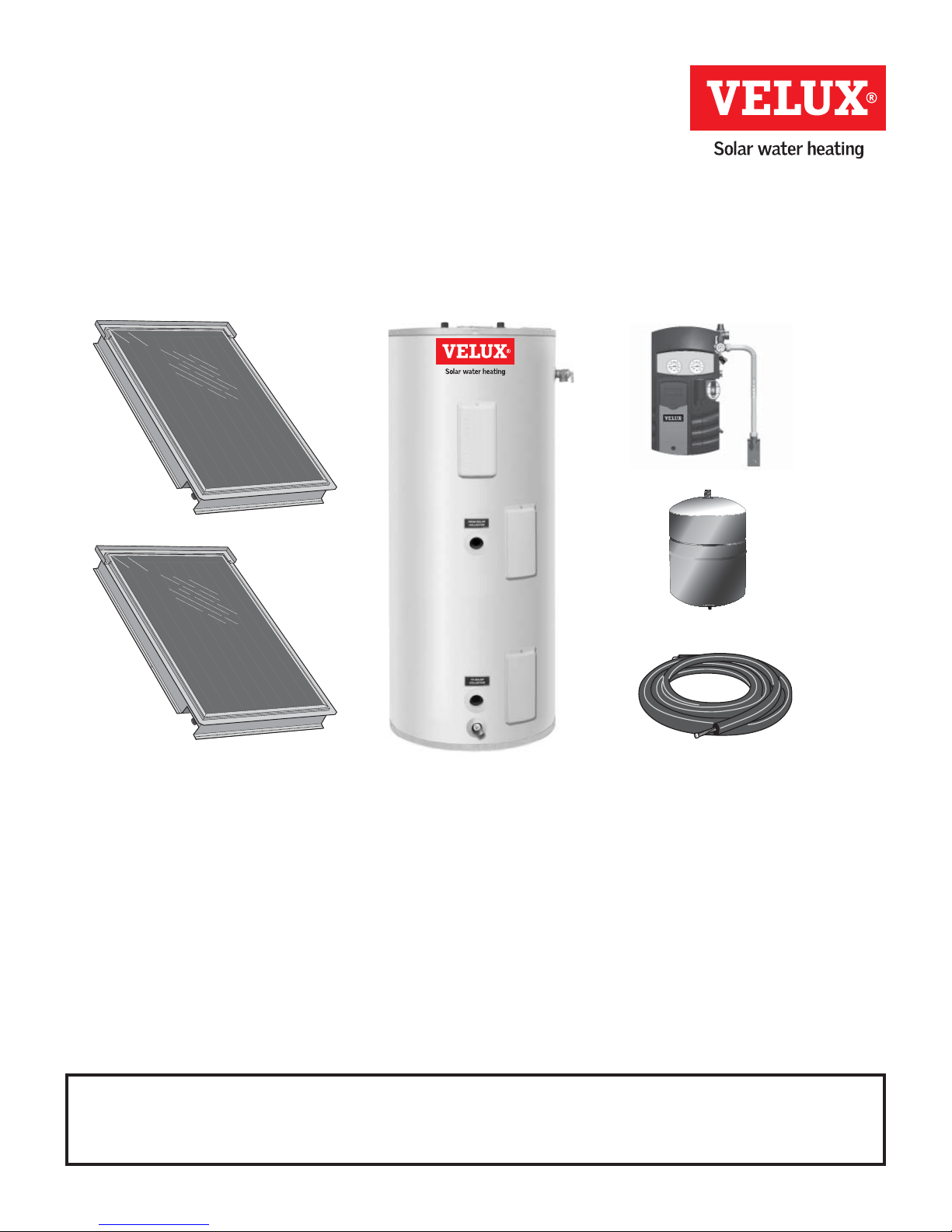
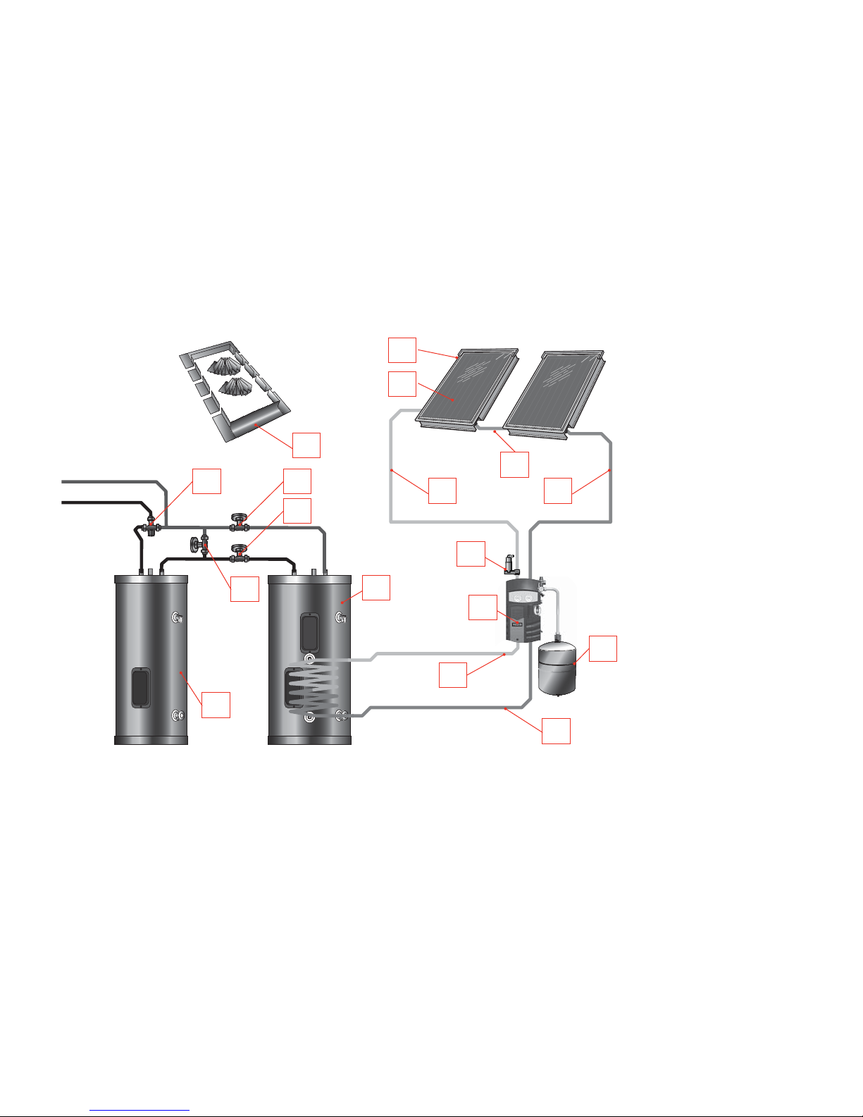
Solar storage tank
All VELUX solar water heating systems will include a solar storage tank with the solar heat exchanger located in the bottom
section of the tank to heat the entire water volume of the tank. The thermostatic controls for the electric, gas, or boiler back
up shall be located in the upper portion of the tank to provide back up heat if the solar collector is not providing enough heat
to maintain the upper operating set point of the tank. The solar tank is equipped with a control well located a third of the way
from the bottom of the tank located near the heat exchanger coil to monitor the solar heat input.
Collector loop piping
VELUX solar water heating systems are designed for use with the pre-insulated corrugated stainless steel flexible piping
provided with the VELUX system kit. Collector piping installation requires the use of copper and brass fittings in the collector
loop. Piping in new solar installations may have dirt, grease, or other impurities that over time aect the quality of the
propylene glycol heat transfer fluid. A thorough cleaning is required before charging the system with glycol. All vertical piping
between the storage tank and the collector shall be supported at each story or at maximum intervals of ten feet (10’) using the
pipe hangers provided. If additional supports are needed, copper plumbers tape or tube strap may be used. The pipe insulation
may not be compressed or crimped by the strapping material. The installation of all horizontal and vertical piping may not
reduce the performance or rating of any structural member or fire rated assembly. Adhere to all applicable local codes and
ordinances.
The collector loop cold supply and hot return lines must be well insulated with the high quality flexible closed cell insulation
provided to minimize heat loss. There shall be no exposed piping or fittings. The wall thickness of the pipe insulation should
not be less than ¾”. To the extent possible, slide the insulation material over the pipe without cutting or taping. All butt joints
must be sealed with contact adhesive. The use of rigid polyethylene pipe insulation is prohibited. The temperatures generated
by your collector in the summer months or under stagnation conditions can melt this type of material. Any above ground
exterior pipe insulation that may be subject to UV degradation must be wrapped with foil tape or painted with two coats of
high quality water-based acrylic resin coating as supplied by the insulation manufacturer. Rubatex UV Protective Coating or
equal is the required coating material.
Pump station controller
All VELUX solar water heating systems include a pump station controller that include the temperature and pressure gauges,
check valves, ball valves, flow meter, fill and drain valves, and dierential controller required to properly operate the VELUX
solar water heating system. The system temperatures for the collector and storage tank can be read from the dierential
controller. Typical tank operating temperatures can range from the cold supply of 40°-80° F up to 180° F which represents
the high limit of the tank. This will vary depending on the climate where the system is installed. The collector temperature
sensor should be 5°-20° F above the tank sensor during normal operation. During idle periods, when there is no sun, the
collector will read the ambient temperature and when there is full sun upward to 250° F.
Balance of systems
The balance of components in all VELUX solar water heating systems: solar loop pipe and fittings, temperature sensors,
expansion tank, microbubble air separator, mixing valve, and non-toxic propylene glycol heat transfer fluid components carry
temperature and pressure ratings required of the VELUX solar water heating system design.
The VELUX solar water heating system can be operated down to ambient temperatures of –40°F using proper concentrations
of propylene glycol. Freeze tolerance limits are based upon an assumed set of environmental conditions. Refer to the propylene
glycol specification sheet in the back of this manual for recommended concentrations. The dierential controller uses
temperature sensors to monitor the temperature dierence between the collector and the solar storage tank. The controller
turns on when the collector is 18–20° F above tank temperature and turns o when the dierential drops below 12° F.

6 – Part 3: Solar water heater system installation – Installation check list
The Contractor shall obtain all required permits and approvals for installing the solar system. The installation shall conform to
all federal, state and local regulations governing solar water heating system installations. The contractor shall adhere to sound
building safety and trade practices. Special consideration must be given to building code requirements for the penetration
of structural members and fire rated assemblies. Before beginning with the installation, the contractor shall inspect the
condition of the roof and notify the homeowner of any existing roof damage or necessary repairs.
Installation check list
Collector location:
South facing within 45 degrees of due south
Roof pitch is between 15–60 degrees of horizontal
Collectors are located in an unshaded area
Collectors are located as close to tank as possible
Roof and roofing material are in good condition
Storage tank location:
Sucient room to service water heater
Provisions made to protect area from water damage
Centrally located to fixtures
Protected from freezing temperatures
Area free of flammable vapors
Potable water supply:
All related piping is free from leaks
Thermal expansion tank installed
Water heater and fixtures have been
properly purged of air
Relief valve:
Temperature and pressure relief valve properly installed
and discharge line runs to open drain
Discharge line is not exposed to freezing temperatures
Discharge line is constructed of copper
Wiring systems with back-up electric element:
Power supply voltage agrees with the water heater
rating plate.
Branch circuit wire fusing or circuit breaker properly
sized.
Electrical connections tight and unit properly grounded
Wiring systems with boiler back-up:
Water heater control is secure in control well
Boiler back-up control is wired back to the boiler control
or relay center
Solar heat exchanger to solar panel
Anti-Freeze is added and is rated as non-toxic with copy
of MSDS sheet for homeowner
Solar heat exchanger is completely purged of air
Expansion tank and pressure temperature gauge are
operating properly
Solar control shows circulators operating properly on
the solar panels
Boiler heat exchanger; boiler back-up systems:
Heat exchanger is completely purged of air
Expansion tank and pressure temperature gauge are
operating properly
Boiler control is operating circulator for the boiler back-
up heat exchanger
Anti-freeze fluid:
Make sure freeze protection fluids are certified as non-
toxic
Glycol percentage must be calculated per local area
freeze level
Provide glycol MSDS sheet to end user
Pump station / Controller
Air bled from pump
System arrangement selected
OCX setting is set
OREC setting is set
Part 3: Solar water heater system installation

VELUX solar water heating system with electric or gas back-up – Part 3: Solar water heater system installation – 7
Cooled glycol
Heated glycol
VELUX solar water heating system with electric or gas back-up
System models: CLI U12 SD0(W/L/F/P) 118 El B/U CLI U12 SD0(W/L/F/P) 1110 NG B/U CLI U12 SD0(W/L/F/P) 1111 LP B/U
CLI U12 SK0(W/L/F/P) 218 El B/U CLI U12 SK0(W/L/F/P) 2110 NG B/U CLI U12 SK0(W/L/F/P) 2111 LP B/U
CLI U12 SK0(W/L/F/P) 318 El B/U
Notes:
1. This drawing is meant to show a system piping concept only. The installer is responsible for all equipment and detailing by local codes.
2. Anti-freeze, non- potable heat transfer fluid shall be used for the solar storage tank heat exchanger circuit only. Never introduce Anti-freeze solution to any
other solar storage tank connection other than the solar heat exchanger.
3. If there is a check valve on the cold water feed line, a thermal expansion tank suitable for potable water must be sized and installed within this piping system
between the check valve and the cold water inlet of the solar storage tank.
4. The an anti-scald mixing valve provided must always be installed as shown.
5. For all electric back-up models, make sure solar storage tank is fully purged of air before power is turned on to the back-up heat source.
8.
11.
7.
6.
5.
9.
4.
2. 3.
1.
10.
4.
4. 4.
1. Collectors
2. Flashing/racking
3. Connector tube
4. Flextubes
5. Air Separator
6. Pump station/controller
7. Expansion tank
8. Solar storage tank
9. Mixing valve
10. Temperature sensor
11. Electric auxiliary with
thermostat
Cold water
Hot water

8 – Part 3: Solar water heater system installation – VELUX solar water heating system with boiler back-up
VELUX solar water heating system with boiler back-up
System models: CLI U12 SD0(W/L/F/P) 119 HX B/U
CLI U12 SK0(W/L/F/P) 219 HX B/U
CLI U12 SK0(W/L/F/P) 319 HX B/U
Notes:
1. This drawing is meant to show a system piping concept only. The installer is responsible for all equipment and detailing by local codes.
2. Anti-freeze, non- potable heat transfer fluid shall be used for the solar storage tank heat exchanger circuit only. Never introduce Anti-freeze solution to any
other solar storage tank connection other than the solar heat exchanger.
3. If there is a check valve on the cold water feed line, a thermal expansion tank suitable for potable water must be sized and installed within this piping system
between the check valve and the cold water inlet of the solar water heater.
4. The an anti-scald mixing valve provided must always be installed as shown.
5. Circulators shown in the hydronic boiler piping above should have an integral flow check or alternately use a stock pump with an external spring type check
valve. (Circulators with integral flow checks are not to be used in solar systems due to extreme temperatures.)
1. Collectors
2. Flashing/racking
3. Connector tube
4. Flextubes
5. Air Separator
6. Pump station/controller
7. Expansion tank
8. Solar storage tank
9. Mixing valve
10. Temperature sensor
11. Auxiliary heat exchanger
12. Backup heat source
provided by another
installation
8.
12.
11.
7.
6.
5.
9.
4.
2.
3.
1.
10.
4.
4. 4.
Cold water
Cooled glycol
Hot water
Heated glycol

VELUX solar pre-heat water heating system – Part 3: Solar water heater system installation – 9
VELUX solar pre-heat water heating system
System models: CLI U12 SD0(W/L/F/P)118 AUX EL CLI U12 SD0(W/L/F/P)118 AUX GAS CLI U12 SD0(W/L/F/P)118 AUX TLG
CLI U12 SK0(W/L/F/P)218 AUX EL CLI U12 SK0(W/L/F/P)218 AUX GAS CLI U12 SK0(W/L/F/P)218 AUX TLG
CLI U12 SK0(W/L/F/P)318 AUX EL CLI U12 SK0(W/L/F/P)318 AUX GAS CLI U12 SKO(W/L/F/P)318 AUX TLG
Notes:
1. This drawing is meant to show a system piping concept only. The installer is responsible for all equipment and detailing by local codes.
2. Anti-freeze, non- potable heat transfer fluid shall be used for the solar storage tank heat exchanger circuit only. Never introduce Anti-freeze solution to any
other solar storage tank connection other than the solar heat exchanger.
3. If there is a check valve on the cold water feed line, a thermal expansion tank suitable for potable water must be sized and installed within this piping system
between the check valve and the cold water inlet of the solar storage tank.
4. The an anti-scald mixing valve provided must always be installed as shown.
5. For all electric back-up models, make sure solar storage tank is fully purged of air before power is turned on to the back-up heat source.
8.
11.
6.
5.
9. 12.
12.
12.
4.
2.
3.
1.
10.
4.
4. 4.
Cold water
Cooled glycol
Hot water
Heated glycol
1. Collectors
2. Flashing/racking
3. Connector tube
4. Flextubes
5. Air Separator
6. Pump station/controller
7. Expansion tank
8. Solar storage tank
9. Mixing valve
10. Temperature sensor
11. Existing gas or electric
water heating
12. Solar system bypass
valves
7.

10 – Part 3: Solar water heater system installation – VELUX solar system components
VELUX solar system components
Listed below are the components needed for installation of the VELUX water
heating system.
1. VELUX solar collector: Absorbs the sun’s energy and transfers this energy
into the heat exchanger located on the bottom of the solar storage tank.
2. VELUX collector flashings/racking: Integrates the solar collectors into the
roofing material for an aesthetic low profile, water tight installation.
3. Solar storage tank: Transfers sun’s energy to the domestic hot water
through the solar heat exchanger located in the tank. Consists of the
following components:
a. Drain valve (Tank): Used to flush sediment which may accumulate on the
bottom of the solar storage tank and also provide a means of draining the
tank.
b. Solar heat exchanger: The solar heat exchanger is designed to transfer
heated energy rapidly from the solar collector into the potable water.
c. Hot water outlet: The solar storage tank has a hot water dip tube outlet
which draws water from the very top of the heater. This helps to keep the
heat trapped inside the highly insulated storage tank.
d. Temperature and pressure relief valve: The relief valve provided complies
with standards for relief valves (ANSI Z21.22). No valve of any type
should be installed between the relief valve and tank. Local codes govern
installation of relief valves. The outlet of the relief valve must be piped
to suitable open drain so that the discharge water cannot contact live
electric parts to eliminate potential damage. Piping used should be
approved for hot water distribution. The valve discharge line must be no
smaller than the outlet of the valve and must be pitched downward from
the valve to allow complete drainage of the relief valve and discharge line.
The end of the discharge piping should be not be threaded or concealed
and should be protected from freezing. No valve of any type, restriction or
reducer coupling should be installed in the discharge line.
e. Back-Up electric element with thermostat (electric back-up systems): The
back electric element will only be activated when the desired minimum
set point temperature set on the back-up thermostat cannot be satisfied
by the solar gain achieved from the solar collector.
f. Back-Up burner with thermostat (NG and LP back-up systems): The
back burner will only be activated when the desired minimum set point
temperature set on the back-up thermostat cannot be satisfied by the
solar gain achieved from the solar collector.
g. Boiler back-up heat exchanger (boiler back-up systems): The back-
up boiler will only be activated when the desired minimum set point
temperature set on the back-up thermostat can not be satisfied by the
solar input from the solar collector.
h. Boiler back-up aquastat (boiler back-up systems): The boiler back-up
aquastat will activate the boiler to circulate the hot water generated
from the boiler into the heat exchanger located on the top section of the
solar storage tank. Once the controller is satisfied and has reached its
desired set point, it will shut o the boiler. This back-up portion will only
be activated if the solar gain achieved from the solar collector can not
keep the tank at the minimum desired temperature setting.
VELUX solar collector
VELUX collector flashings
Solar storage tank
Solar water heating

VELUX solar system components – Part 3: Solar water heater system installation – 11
4. Pump station controller: Operational control center for VELUX solar
systems. All solar loop system safety devices, temperature gauges,
pressure gauges, fill valves and drain valves are housed within or
attached to the pump station controller. Consists of the following
components:
a. Solar controller: The solar controller, turns on or o solar loop circulator
depending on the heat gained in the solar collectors. The controller will
also limit over heating in the solar collectors and overheating in the solar
storage tank.
b. Tank and heat exchanger temperature and pressure and gauges: The
temperature and pressure gauges in the pump station controller will
show the user the actual temperature and pressure being supply and
returned to the solar collector and through the heat exchanger.
c. Check valves: Check valves located in the “hot” and “cold” lines of pump
station controller help minimize the convective heat loss at night when
the system is not operating. If check valves are not installed, most of
the heated energy stored during the day would be transferred back up
into the collectors and lost.
d. Collector array isolation valves: Valves located in the “hot” and “cold”
lines of pump station controller are used to isolate the solar collector
loop from the solar storage
tank.
e. Pressure relief valve (for
solar loop): Will release the
pressure in the solar loop when
it exceeds 82 PSI. If the valve
opens and releases fluids,
than it is recommend that
you contact your contractor
immediately.
f. System fill valve: Used to fill the
system with heat transfer fluid
and also eliminate air from the
system.
g. System drain valve: Used to
charge the collector loop with
propylene glycol, purge air from
loop and drain the solar water
heating system of heat transfer
fluid.
h. Circulator: Circulates the heat
transfer fluid from the solar
collectors into the solar storage
tank heat exchanger.
i. Ball valve (for circulator): Used
to isolate the circulator pump
for service and when filling the
system with heat transfer fluid.
Pump station controller
Inside a pump station
controller
a.
e.
f.
h.
g.
i.
b. c. d.

12 – Part 3: Solar water heater system installation – VELUX solar system components
5. Other system components
a. Anti-Scald Mixing Valve: Automatically
blends the hot water and the cold water feed
line to control the discharge temperature to
an acceptable and safe temperature. This will
also increase the amount of hot water that
is drawn from the solar storage tank by not
allowing the incoming water to fully temper
the hot water stored inside the tank.
b. Expansion tank: Pre-charged with air to allow
for the expansion as the heat transfer fluid
expands and contracts with heating and
cooling.
c. Solar collector temperature sensor
This sensor is wired to the solar controller
and automatically turns on the circulator
pump when the dierential set point is
reached between the solar water heater and
the solar collector.
d. Tank temperature sensor: The tank sensor
is wired to the solar controller to measure
the temperature on the bottom of the solar
storage tank.
e. VELUX flexible piping: Pre-insulated
corrugated stainless steel flexible piping
designed specifically for VELUX solar loop
piping. VELUX has designed a special cone
shaped fitting which ensures a tight and
secure connection to collectors without
requiring a gasket or o-ring seal.
f. Microbubble air separator: This automatic
air vent is used in the solar system to allow
air contained in the system to be released.
The air vent valve is designed to work in
high temperatures( as high as 350°F) with a
propylene glycol medium.
g. Propylene glycol heat transfer fluid: Non-
toxic fluid used to transfer heat from solar
collectors to solar storage tank. Includes
corrosion inhibitors to prevent corrosion of
solar loop components.
Anti-Scald Mixing Valve
Expansion tank
Propylene glycol
Tank temperature sensor
Collector temperature sensor
VELUX flexible piping
Microbubble air separator

Solar collector orientation – Part 3: Solar water heater system installation – 13
Solar collector orientation
Operating your VELUX solar water heater for optimal eciency is based on the correct orientation, pitch, and location of
the solar collectors. In North America, collectors should be oriented due south, however may be oriented up to 45 degrees
east or west of due south with minimal losses in solar gain. Optimal pitch is +/– 10° from the latitude of the installation site.
VELUX collectors must be installed at a minimum pitch of 15 degrees from horizontal, and for optimal performance, the
recommended pitch is between 15–60 degrees. The collector should be mounted as close to the storage tank as possible
to minimize heat loss in the piping runs. The solar collector must be located in an area of the roof that will be unshaded for
the majority of the day (from 9:00–3:00) all year round. Adjacent buildings and trees should be checked for possible winter
shading.
Collector installation
The most important structural consideration is to securely anchor the solar collector to the structural members of the roof
with the stainless steel mounting screws provided. Preserving the integrity of the roof membrane is the most important
roofing consideration. Ensure that the solar collectors can be properly flashed and sealed in accordance with standard roofing
practices and the VELUX flashing instructions. Reference your VELUX collector installation manual for proper guidelines in
your application. All equipment should be installed in accordance with all local codes and best practices as identified with
National Roofing Contractors Association (NRCA) or other qualified body.
1. Open the packaging for the collectors and flashings. Carefully read all provided installation instructions.
2. Prepare the roof for collector mounting. If needed, carefully remove shingles to expose underlayment. Mark o the
location of the collectors and nail a temporary collector support to roof.

14 – Part 3: Solar water heater system installation – Collector location on 16” o.c. rafters
CLI U12 4000 • 2 Collector layout • 16” o.c. rafters
CLI U12 4000 • 3 Collector layout • 16” o.c. rafters
Collector location on 16” o.c. rafters

Collector location on 24” o.c. rafters – Part 3: Solar water heater system installation – 15
CLI U12 4000 • 2 Collector layout • 24” o.c. rafters
CLI U12 4000 • 3 Collector layout • 24” o.c. rafters
Collector location on 24” o.c. rafters

16 – Part 3: Solar water heater system installation – Collector installation
3. Mark o the location for the flexible piping penetration locations. Verify that there are no roof joists or obstructions
prior to drilling, then drill, or cut openings for piping penetrations.
4. Carefully place collectors on roof. Place collector against temporary support and align them so that the flexible
piping connections align with the openings cut into the roof deck. Ensure that there is 4” of space between
collectors (measured to the vertical wall casing). Secure collector top support flange to roof deck using four self-
tapping stainless steel mounting screws (provided). When possible, screws shall be located to secure the collectors
to the roof trusses below.
5. Open the packaging for the ZFM flexible pipes (to be used to connect the collectors to the pump station). Identify
ZFM flexible pipe connection end for connection to the pump station (end with red/blue tabs) and the connection
end for connection to the collector (end with cone shape). Route the collector ends up through the roof and attach
flexible piping to collectors. Secure flexible piping nuts securely using wrench.

Collector installation – Part 3: Solar water heater system installation – 17
6. Open the packaging for the ZFR flexible pipes (to be used for interconnection between two collectors). The ZFR pipes are
a fixed length and are not to be cut -- the cone shaped end connections on these pipes are designed specifically for use
with VELUX collectors. Route the ZFR pipes between the collectors and attach to collectors. Secure nuts securely using
wrench. Fully insulate flexible piping connections with insulation and tape provided.
7. Locate the end of the flexible pipe connected to the bottom left corner of the collector bank (this is the heat transfer fluid
“hot” pipe). Locate the indicator tab near the end connection. Tear o “blue” tab from the indicator tab, leaving the “red”
tab in place -- this will help to identify this pipe as the “hot” pipe later in the installation.
8. Locate the end of the flexible pipe connected to the bottom right corner of the collector bank (this is the heat transfer fluid
“cold” pipe). Locate the indicator tab near the end connection. Tear o “red” tab from the indicator tab, leaving the “blue”
tab in place -- this will help to identify this pipe as the “cold” pipe later in the installation.

18 – Part 3: Solar water heater system installation – Collector installation
9. Locate the collector temperature sensor, couplant tube, and extension cable. Locate the collector temperature sensor
well in the top left corner of the collector bank (collector with “hot” pipe connected). Fill the collector sensor port with
couplant and then insert sensor into the sensor well. Secure the sensor in place with insulating tape.
10. Connect the extension cable to the collector temperature sensor and route sensor cable along side of collector through
the roof opening for the “hot” pipe. Drill a 1” hole alongside the collector flange between the sensor port and the hot pipe.
Route the cable through the 1” hole and align along collector flange.
11. Secure the side flanges of the collectors to the roof structure using four self-tapping stainless steel mounting screws
per side. When possible, screws shall be located to secure the collectors to the roof trusses below. Carefully remove
the temporary support from the bottom edge of the collectors and secure the bottom flange of all collectors to the roof
structure using the remaining self-tapping stainless steel mounting screws.

Flashing installation – Part 3: Solar water heater system installation – 19
Flashing installation
Install the VELUX flashings ensuring that the collectors are properly flashed and sealed in accordance with standard roofing
practices and the VELUX flashing instructions. Reference your VELUX collector installation manual for proper guidelines in
your application. All equipment should be installed in accordance with all local codes and best practices as identified with
National Roofing Contractors Association (NRCA) or other qualified body.
1. Install the bottom pan flashings and gutters and secure in place using metal tabs as referenced in the VELUX
flashing instructions. Do not drive roofing nails, screws, or other fasteners, through the flashings to secure.
2. Install the first course of roofing material and VELUX flashings along left side of collector bank. Repeat procedure
along right side of collector bank.
3. Install the top pan flashings and secure in place using metal tabs as referenced in the VELUX flashing instructions.
Finish the flashing installation by installing the collector cladding and the last course of roofing material.

20 – Part 3: Solar water heater system installation – Flashing installation
Solar storage tank and pump station controller location
Choose a location for your solar storage tank and pump station controller centralized to the domestic hot water piping system.
You must also locate the solar storage tank and related domestic piping where it will not be exposed to freezing temperature.
All piping should be insulated. The storage tank should be installed so there is access to the electric element and thermostat
for future service. If you do not provide minimum clearances, it might not be possible to service the tank without removing
it from the space. The tank should also be placed in a location where T&P discharge or a leak will not result in damage to the
surrounding area. If you do not have this location requirement available, you must use an auxiliary catch pan.
Provide clear access to the storage tank, pump station controller, expansion tank, mixing valve, and other key components.
The components on the potable side of the system may require future service or maintenance, so it is recommended that the
connections be made with brass unions. You must use the VELUX pipe and fittings in plumbing the solar loop for the solar
storage tank and the expansion tank. The use of galvanized fittings, nipples, di-electric unions, CPVC, PVC or other plastic pipe
is prohibited.
Hard copper connections to the city cold water supply line and home hot water feed lines are recommended. The gaskets in
standard water heater flex hose connectors can become brittle and compressed over time and begin leaking on the water
heater. If not detected in a timely manner, even a drip or leak may cause serious damage to the tank’s electrical components or
in extreme cases, may cause the tank to leak from the outside in.
!WARNING
Do not introduce heat transfer fluids into any fittings on the tank except those clearly marked for that purpose. Heat
transfer fluid must be classified as non-toxic. See HTF specification in the back of this manual.
4. Cover the solar collectors before proceeding to the next step of the system installation procedure.
Maximum 2”
Diameter of water heater
plus 2” minimum
To open drain,
line should be
at least 3⁄4” ID
and pitched for
proper drainage.
6” Min
Clearance
24” Min
Clearance
No min
Clearance
6” Min
Clearance
This manual suits for next models
6
Table of contents
Other Velux Heating System manuals
Popular Heating System manuals by other brands

CTC Union
CTC Union EcoZenith C 530 Installation and maintenance instructions

Napoleon
Napoleon Condo Pack CAGMMA installation instructions

Hi-Velocity
Hi-Velocity HE Series installation manual

RBM
RBM PAD INDOO instruction manual

Salda
Salda RIS 400 P EKO 3.0 Series MOUNTING AND INSTALLATION INSTRUCTION

Extraflame
Extraflame LUCREZIA IDRO LCD user manual

Toyotomi
Toyotomi FF-V30 Operation instructions

Aqua-Hot
Aqua-Hot 400 series Service manual

Mitsubishi Electric
Mitsubishi Electric Ecodan HUS210FTC4ST installation manual

Frost Italy
Frost Italy SIAL slim Operation manual

Myson
Myson SLIM-LINE RC Installation & maintenance manual

Carrier
Carrier 48ZG User's information manual