Sunstar Precision SWF Series User manual

SSUUNNSSTTAARR PPRREECCIISSIIOONN CCOO..,, LLTTDD..
MANUAL
FOUR-HEAD AUTOMATIC
EMBROIDERY MACHINE WITH
FLAT
SWF/D- Series
SIX-HEAD AUTOMATIC
EMBROIDERY MACHINE WITH FLAT
MMMMEE--

THIS IS AN INSTRUCTION FOR SAFE USE OF
4, 6-HEAD FLAT AUTOMATIC EMBROIDERY
MACHINES. READ THOROUGHLY BEFORE USE.

i
CHAPTER 1 SAFETY RULES …………………………………………………………………… 1-1
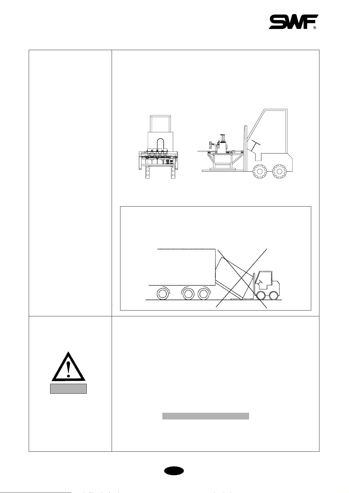
1-1) MACHINE DELIVERY ……………………………………………………………… 1-1
1-2) MACHINE INSTALLATION ………………………………………………………… 1-2
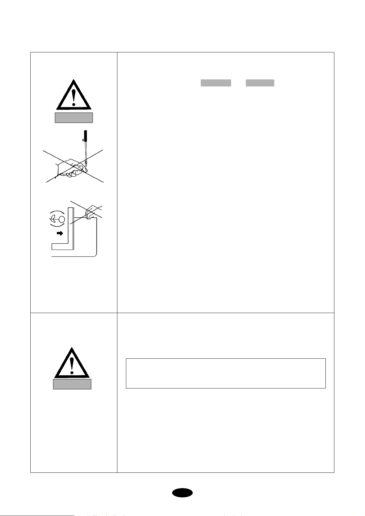
1-3) MACHINE OPERATION …………………………………………………………… 1-3
1-4) REPAIR ……………………………………………………………………………… 1-3
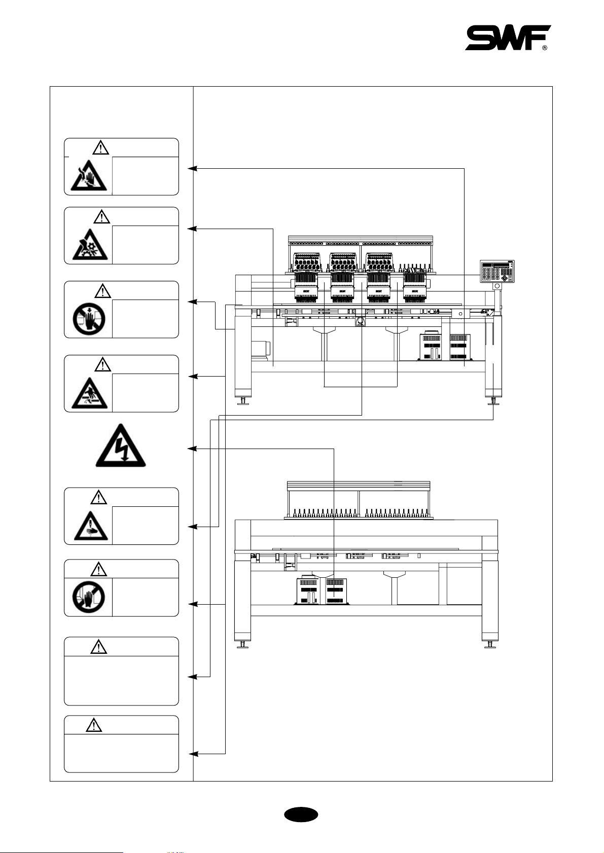
1-5) PLACEMENT OF WARNING STICKERS ………………………………………… 1-4
1-6) CONTENTS OF WARNING STICKERS …………………………………………… 1-5
CHAPTER 2 INSTALLATION AND MACHINE ASSEMBLY ………………………………… 2-1
2-1) ENVIRONMENT …………………………………………………………………… 2-1
2-2) ELECTRICITY………………………………………………………………………… 2-2
2-3) LEVELING THE MACHINE ………………………………………………………… 2-3
2-4) ASSEMBLY OF PERIPHERAL DEVICES
CHAPTER 3 PARTS OF THE MACHINE ………………………………………………………… 3-1
CHAPTER 4 FUNCTIONS AND FEATURES …………………………………………………… 4-1
CHAPTER 5 FUNCTIONS FOR BASIC MACHINE OPERATION ……………………………… 5-1
5-1) NAMES AND FUNCTIONS OF PARTS IN OPERATION BOX ………………… 5-1
5-2) EMERGENCY POWER AND START/STOP/BAR SWITCH ……………………… 5-4
5-3) EMERGENCY STOP ………………………………………………………………… 5-6
5-4) LAMP ON THREAD TENSION ADJUSTMENT BOARD ………………………… 5-7
5-5) NEEDLE STOP CLUTCH (JUMP) ………………………………………………… 5-8
5-6) UPPER THREADING AND TENSION ADJUSTMENT …………………………… 5-9
5-7) LOWER (BOBBIN) THREADING AND TENSION ADJUSTMENT ……………… 5-12
5-8) BOBBIN WINDER …………………………………………………………………… 5-13
5-9) FLOPPY DISKS ……………………………………………………………………… 5-16
5-10) IN AND OUT OF DESIGNS ……………………………………………………… 5-18
5-10-1) FLOPPY …………………………………………………………………… 5-18
5-10-2) TAPE ……………………………………………………………………… 5-18
5-10-3) EMBROIDERY OUTPUT ………………………………………………… 5-18
5-11) RETURN TO PREVIOUS LOCATION IN UNEXPECTED BLACKOUTS ……… 5-18
5-12) NEEDLE- HOOK TIMING CONTROL …………………………………………… 5-19
5-13) ASSEMBLY AND FUNCTIONS OF THREAD DETECTOR …………………… 5-24
5-13-1) FUNCTIONS OF THREAD DETECTOR ………………………………… 5-24
5-13-2) DISASSEMBLING THREAD DETECTOR ……………………………… 5-24
CHAPTER 6 BASIC MACHINE OPERATION …………………………………………………… 6-1
CHAPTER 7 NAVIGATING THE CONTROL PANEL …………………………………………… 7-1
7-1) INSTALLING THE OPERATING SYSTEM ……………………………………… 7-1
7-2) MAIN INDICATION SCREEN ……………………………………………………… 7-7
7-3) THE FUNCTION MENU …………………………………………………………… 7-9
7-3-1) OUTLINE OF FUNCTION MENU ………………………………………… 7-9
7-3-2) FUNCTION MENU DIAGRAM …………………………………………… 7-10
7-4) USE OF FUNCTION MENU ………………………………………………………… 7-11
7-4-1) IN AND OUT OF DESIGNS ……………………………………………… 7-11
7-4-2) BASIC SET-UP FUNCTIONS ……………………………………………… 7-22
7-4-3) SUB WORK ………………………………………………………………… 7-27
7-4-4) REPETITION WORK ……………………………………………………… 7-32
TABLE OF CONTENTS

ii
7-4-5) EMBROIDERY DATA SET-UP …………………………………………… 7-37
7-4-6) EMBROIDERY DESIGN EDITING ……………………………………… 7-42
7-4-7) FRAME MOVEMENT …………………………………………………… 7-51
7-4-8) FLOAT (NON-STITCHING FUNCTIONS) ……………………………… 7-53
7-4-9) MACHINE DATA SET-UP ………………………………………………… 7-54
7-4-10) THE FLOPPY DRIVE AND DISK ……………………………………… 7-58
7-4-11) MANUAL CUTTING ……………………………………………………… 7-61
7-4-12) OFFSET SET-UP ………………………………………………………… 7-61
7-4-13) NEEDLE BAR SELECTION ……………………………………………… 7-63
CHAPTER 8 ERROR MESSAGES AND CORRECTION ……………………………………… 8-1
8-1) MAIN SHAFT MOTOR ……………………………………………………………… 8-1
8-2) PULSE MOTORS ON X AND Y AXIS ……………………………………………… 8-1
8-3) COLOR CHANGE …………………………………………………………………… 8-1
8-4) ENCODER …………………………………………………………………………… 8-2
8-5) REPETITION WORK ………………………………………………………………… 8-2
8-6) FLOPPY DRIVE & COMMUNICATION …………………………………………… 8-2
8-7) TAPE READER & COMMUNICATION …………………………………………… 8-3
8-8) MEMORY …………………………………………………………………………… 8-3
8-9) SYSTEM INSTALLATION ………………………………………………………… 8-3
CHAPTER 9 THE CONTROL BOX ……………………………………………………………… 9-1
9-1) CHANGING FUSE IN JOINT BOARD OF M/C WITH LESS THAN 12 HEADS …9-1
9-2) STANDARD VOLTAGE FOR X, Y DRIVERS (BY MACHINE TYPE) ………… 9-2
CHAPTER 10 MAINTENANCE AND INSPECTION …………………………………………… 10-1
10-1) CHECK POINTS FOR REGULAR INSPECTION ………………………………… 10-1
10-2) CLEANING ………………………………………………………………………… 10-1
10-3) OIL SUPPLY ………………………………………………………………………… 10-3
10-4) DRIVE BELT TENSION …………………………………………………………… 10-7
CHAPTER 11 MACHINE ADJUSTMENTS ……………………………………………………… 11-1
11-1) ADJUSTING THE TRIMMERS …………………………………………………… 11-1
11-1-1) ADJUSTING THE POSITION OF THE TRIMMING CAM
(INSERT ANGLE OF MOVABLE BLADE) …………………………… 11-1
11-1-2) ADJUSTING SPACE BETWEEN MOVABLE BLADE AND HOOK …11-2
11-1-3) ADJUSTING BLADE TENSION ………………………………………… 11-2
11-1-4) ADJUSTING TENSION ON LOWER THREAD HOLDER …………… 11-3
11-2) ADJUSTING THE TRIMMER RETURN SPRING ………………………………… 11-3
11-3) PICKER ADJUSTMENT …………………………………………………………… 11-4
11-4) ADJUSTING UPPER THREAD HOLDER ………………………………………… 11-4
11-5) ADJUSTING HEIGHT OF PRESSER FOOT ……………………………………… 11-6
11-6) CORRECT POSITION OF NEEDLE ……………………………………………… 11-7
11-7) ADJUSTING HALF-TURN FILM FOR COLOR CHANGE ……………………… 11-8
11-8) ENCODER ADJUSTMENT ………………………………………………………… 11-8
11-9) JUMP SOLENOID ADJUSTMENT ………………………………………………… 11-9
CHAPTER 12 TROUBLESHOOTING ……………………………………………………………… 12-1
CHAPTER 13 BLOCK DIAGRAM ………………………………………………………………… 13-1

1-1
The following set of safety rules categorized as DANGER, WARNING, and CAUTION indicates possibilities of
physical or property damages if not fully observed.
: These safety instructions MUST be observed to be safe from danger when installing, delivering, or
repairing the machine.
: These safety instructions MUST be observed to be safe from machine injuries.
: These safety instructions MUST be observed to prevent predictable machine errors.
CAUTION
WARNING
DANGER
SAFETY RULES
CHAPTER 1
ONLY TRAINED AND EXPERIENCED PERSONS, FAMILIAR WITH THE
RELEVANT SAFETY INSTRUCTIONS, SHOULD HANDLE THE
MACHINE. MAKE SURE TO FULLY OBSERVE THE FOLLOWING
INSTRUCTIONS.
1) Using a crane
Make sure that the crane is large enough to hold the machine. Use a nylon
rope of sufficient strength. Place a wooden block at either side of the
machine before tying the rope. The angle should be 40�or less. Make sure
that the rope does not touch the table.
※Make sure all persons
and obstacles are out
of the way of the
moving equipment.
[Fig.1-1]
1-1) MACHINE
DELIVERY
DANGER
Wooden block
Nylon rope
Max. 40�
Max. 40�
Bolt
Nut

1-2
2) Using a Forklift
Make sure that size and weight of the forklift is sufficient to support the
machine. Use the pallet to place the machine so that its center is on the
forklift arm (see [Fig.1-2]). Lift the machine carefully so that the machine
does not tilt to either side.
[Fig.1-2]
Installation environment may incur machine malfunction or breakdown.
Make sure to meet the following conditions.
1) The foundation under the machine, i.e. table or desk, must be strong enough
to support the weight of the machine (approximately 1 ton).
2) Air conditioning can eliminate dust and humidity that can cause pollution
and corrosion of the machine. Make sure your machine is regularly cleaned.
3) Long exposure to direct sunlight can cause the paint of the machine to fade
or change of the machine shape.
4) Allow at least 50cm (20 inches) of space on each side of the machine for
convenient maintenance.
※Please refer to for installation details.
2. Machine Installation and Assembly
1-2) MACHINE
INSTALLATION
CAUTION
[WARNING]
Make sure to maintain the weight balance in machine deliveries,
especially when unloading the machine from a forklift or crane, in
order to prevent injury or machine damages.

1-3
Only SWF-trained and selected repair engineers should do repair work.
1) Turn OFF the power before cleaning or repairing the machine. Wait for 4
minutes so the machine electricity is completely discharged.
2) Do not change the settings or any parts on the machine without
confirmation from SWF. Such change may cause safety accidents.
3) Use only SWF parts when repairing your machine.
4) Replace all safety covers when you are finished with your repair.
1-4) REPAIR
DANGER
The SWF Automatic Embroidery Machine is designed for applying
embroidery to fabric and other similar materials.
Pay careful attention to the and stickers on certain
parts of the machine. Make sure to observe the following when operating
the machine:
01) Read thoroughly and fully understand the manual before operating the
machine.
02) Dress for safety. Long and unbound hair, jewelry such as necklaces,
bracelets, and wide sleeves can get caught in the machine. Wear shoes with
non-slip soles.
03) Clear all persons from the machine before turning on the power.
04) Keep your hands or head away from the moving parts of the machine such
as needle, hook, take-up lever, and pulley when the machine is in
operation.
05) Do not remove the safety cover on the pulley or shaft when the machine is
in operation.
06) Be sure the main power is turned off and the power switch is set to OFF
before opening the cover of any electrical component or control box.
07) Be sure the main switch is OFF before manually turning the main shaft.
08) Turn the machine off when threading needles or inspecting the finished
embroidery.
09) Do not lean against the cradle or place your fingers near the guide grooves
of the frame.
10) The machine noise may exceed 85db when it is run at a maximum speed. It
is not higher than the standard level, but you may need earplugs or sound-
proof facilities for the operator and other workers.
CAUTIONWARNING
1-3) MACHINE
OPERATION
[CAUTION]
It takes about 10 minutes after turning off the main switch before the
electricity is fully discharged from X/Y main shafts and the drive box.
WARNING

1-4
1-5)
PLACEMENT OF
WARNING STICKERS
WARING
Fire or death may be caused by
high voltage electric shock.
Don’t open the cover except for
service man assigned by SWF.
When open the cover turn off
power and wait for 6 minutes.
[Fig.1-4] From top
CAUTION
Physical damage may be caused by winding
Don’t put your hands near the needle bar &
take-up lever while machine is runing.
Injury may be caused by winding.
Be sure to turn off the power
before cleaning, lubricating,
adjusting or repairing.
Physical damage may be
caused by winding.
Don’t put your hands near the
arrow while the main shaft is
rotating
Injury may be caused by moving
needle.
Ensure that the machine is in a
stop condition before changing,
threading or rethreading of
needies or changing of needles.
①Turn off the main power before rotating the
main shaft by hand!
②Do not remove covers during operation!
③Turn off the main power before opening
electricity-related boxes!
WARING
WARING
WARING
WARING
Physical damage may be caused
by interposition.
While embroidery frame is running
according to the direction of
embroidery frame may be injured
your hands by gap between fixed
body and embroidery frame.
WARING
WARING
Physical injury may be caused
by crevice.
Don’t put your finger in a groove
on the table.
[Fig.1-3] Front
Observe the directions on ALL warning stickers placed on the machine as
reminders for your safety.
1) Location of Warning Stickers

1-5
1) Warning
ⓐ
ⓑ
1-6) CONTENTS OF
WARNING
STICKERS
WARNING
WARNING
Injury may be caused by moving needle.
Ensure that the machine is in a stop
condition before changing, threading or
rethreading of needies or changing of
needles.
ⓒ
WARNING
Fire or death may be caused by high
voltage electric shock.
Don’t open the cover except for service
man assigned by SWF.
When open the cover turn off power and
wait for 6 minutes.
[ Notice ]
Cover in the “WARNING” means all covers near
operating part of the machine.
Injury may be caused by winding.
Be sure to turn off the power before
cleaning, lubricating, adjusting or
repairing.

2-1
Install your machine in an appropriate environment and with adequate electrical supply. Failure to follow the
directions may result in machine malfunction.
2-1) ENVIRONMENT
1) Temperature: ①0 �40℃(32 �104°F) when the machine is in operation
②-25 �55℃(-13 �131°F) when the machine is not in operation
2) Humidity: 45 �90% (relative)
3) Grounding: Ensure the electricity is properly grounded.
4) Close any doors and windows near the machine to prevent direct light, dust, and humidity.
5) Foundation under the machine must be a sufficiently strong and flat concrete to support the weight of the
machine.
2-2) ELECTRICITY
Check if the input voltage of the machine is in the right range of the voltage supply before installing or operating
the machine. The voltage required is as follows:
1) Input voltage (to be adjusted when installing): 100V, 110V, 120V, 200V, 220V, 240V
2) Allowed range of voltage: within ±10% of the voltage set
3) Electric capacity and voltage consumption: 640VA 440W
4) Insulation resistance: over 10M ohms (measured with 500V insulation tester)
INSTALLATION AND MACHINE ASSEMBLY
CHAPTER 2
WARNING
DANGER
Properly ground the machine to avoid the possibility of electric shock. Use three-wire grounding
(grounding resistance below 100 ohms).
�Check the voltage supply where the machine will be installed.
�Install the cable away from the operator’s work space to prevent accident or injury.
[CAUTION]
�Do NOT let moisture drops on the machine.
�Provide air conditioning to control humidity and to prevent dust and corrosion.

2-2
2-3) LEVELING THE MACHINE
The machine must be accurately leveled (especially front and back) to prevent the needle from moving out of
position.
1) Use the adjusting bolts installed at the four stands to level the machine (front, rear, left, and right). Use a level
gauge.
①Check the voltage supply where the machine will be installed.
②Install the cable away from the operator’s work space to prevent accident or injury.
③If the difference in heights of the four bolts is over 10mm, place spacers beneath the lower adjusting bolts to
make the heights even.
2) Use a nut to fasten the bolts when the machine is horizontally leveled.
[CAUTION]
The level gauge does not measure accurately on a square pipe or a table.
[Fig.2-2]
3) Using the level gauge
[Fig.2-3]
[Fig.2-1]
Level gauge
Level gauge
Adjusting bolts
Level base
○○××××

2-3
2-4) ASSEMBLY OF PERIPHERAL DEVICES
1) Assembling Upper Thread Stand
[Fig.2-4]
[Fig.2-5] [Fig.2-6]
2) Assembling Operation Box
Spool plate
Thread holder
Operation box
FDD
Support
CN6(I/O Board to thread joint Board 40P)
CN2(From SPMS to joint & PC∙Power input)
CN5(Joint Board to I/O Board 34P)
CN5(Joint
Board to I/O
Board 30P)

3-1
[Fig.3-1]
Machine Body
Table
Upper thread stand
Main shaft drive motor
Rotary hook base
Trimming cam box
Arm
Color Change
Upper thread holder
Head
Thread tension adjustment board
Sub-controller
X-axis driving system
Y-axis driving system
Bar switch
Frame
Main controller box
Operation box
Encoder
Main power switch
Lamp
Supporting bolt
Leveling base
Thread detector
Emergency power switch
Emergency stop switch
PARTS OF THE MACHINE
CHAPTER 3

4-1
1) EXPANDED MEMORY SIZE
The machine can store a maximum of 100 designs. The basic memory size is 2 million stitches.
2) MIRROR IMAGE CONVERSION AND DESIGN DIRECTION
You can turn the design from 0�to 359�in the increments of 1�and also reverse the design in the X direction
(mirror image).
3) ENLARGING AND REDUCING DESIGN
You can reduce or enlarge the embroidery design in size from 50% to 200% by 1% along the X and Y axis.
4) AUTOMATIC SELECTION OF NEEDLE BAR
You can select the order of the needle bars up to the 99th bar.
5) GENERAL REPETITION WORK
The same design can be repeated up to 99 times along the X and Y axis.
6) AUTOMATIC OFFSET
The frame automatically returns to the offset point when the embroidery is finished to make it easier for you to
switch the frames. You can select AUTOMATIC OFFSET at PARAMETER SELECT MODE to move the frame
automatically to the desired point, making it easier to do appliques and to switch the frames.
7) MANUAL OFFSET
You can manually move the frame to the pre-selected point to do appliques or change the frames during embroidery
work. The frame can be moved back to its original place by simply pressing the right buttons.
8) RETURN TO START
The frame can be moved back to the start point of the design during the embroidery work.
9) NON-STITCHING
The frame and the needle bar can move back and forth by the units of 1, 100, 1000, and 10000 stitches and by color
without stitching.
10) FRAME REVERSAL
When the thread breaks or runs out of track, you can move the needle bar back to the starting point of the design in
the units of one to ten stitches.
11) AUTOMATIC TRIMMING
The automatic trimming function, determined by the design and the machine set-up, enhances work productivity and
quality of the finished product.
FEATURES AND SPECIFICATIONS
CHAPTER 4

4-2
12) AUTOMATIC DETECTION OF UPPER AND LOWER THREAD BREAKS
The machine detects when the upper thread breaks or the lower thread is out of the needle and automatically stops
the machine.
13) AUTOMATIC RETURN TO STOP POINT IN UNEXPECTED BLACKOUT
When the power fails unexpectedly, the frame moves back to the exact point where the stitching stopped. This helps
reduce the number of defects.
14) 3.5'' FLOPPY DRIVE (EMBEDDED)
A 3.5'' floppy drive is embedded in the operation panel for you to read or store designs. Both 2DD and 2HD disks
can be used.
15) EDITING
You can delete, change, or insert stitch data and function codes (jump, finish, trimming).
16) INDIVIDUAL HEAD OPERATION
You can work on the specific head with a broken thread.
17) MACHINE STOPPAGE
The screen will indicate why the machine has stopped.
18) RPM
The screen indicates rpm.
19) FRAME SPEED SET-UP
You can adjust the frame speed to high, medium, or low.
20) UNUSED MEMORY
The screen indicates the memory available for use.
21) TAPE CODE COMPATIBILITY
2-binary and 3-binary tape codes can be edited.
22) 800 *600 COLOR LCD MONITOR (OPTIONAL)
You can install a 800
*
600 color LCD monitor onto your operation panel for easier reading of data.
23) CODES FROM OTHER BRANDS
The machine can automatically read designs of various formats stored in the floppy disk. These formats include
SST/ DST, DSB, DSZ/ TAP/ FMC, FDR/ ZSK/ 10O/ EXP.

5-1
5-1) NAMES AND FUNCTIONS OF PARTS IN OPERATION BOX
FUNCTIONS FOR BASIC MACHINE OPERATION
CHAPTER 5
[ Front Side ]
LCD Menu Screen
Shows 4 lines of 20 letters and indicates the menu you selected using key .
Cursor Button
Moves the cursor on the screen .
Machine Information Screen
Indicates one of the four machine information you selected using key .
Indicator Lamp
Indicates FIX POS (Fixed Position) which indicates the main shaft is not moving. RUN MODE indicates that the
machine is ready to accept and run the design.
Machine Information Button
Selects machine information to be displayed on the screen . See 7.2 MAIN INDICATION SCREEN for details.
Menu Button
Selects the desired menu
[Fig.5-1]
M-SETTING FDD TRIM
OFFSET
PREVIOUSNEEDLE
FLOATFRAME
EDIT
MACHINE
REPEAT
SUB WORKSETTING
EMB. CALL
START
STOP
RUN MODE
FIX POS
DESIGN INFO
STITCH INFO WORK INFO NEEDLE INFO
SUNSTAR PRECISION CO., LTD.

5-2
Number Buttons
This is used to input numbers when setting parameters.
STOP Button
Stops the machine or performs reverse work
START Button
Starts the machine
Frame Movement and Speed Button
Moves the frame left, right, up, and down. Press the lamp key in the center to set the speed of the frame move to
low, medium, or high.
Main Shaft Speed Button
Changes the speed (by unit of 10 rpm) of the main shaft during operation. Press [UP] to increase and [DOWN] to
decrease the speed.
./ALL Button
You can use this to input decimal numbers when setting the interval of repetition work. It can also be used to work
on the previous head after back stitching.
[NOTE]
function
Selects menu
Sets number inputs
Completes work: when the machine stops during operation, hold [SET] key until you hear a loud beep.
The machine will complete the work (Press [SET] until the RUN MODE indicator light is turned off).
CAUTION
CHANGING NEEDLE BAR WITH [SET] KEY
If you want to change the needle bar during operation, press number key and then
[SET].

5-3
Acryl cover: protects the floppy disk drive
Disk Out: takes the disk out
FDD: runs and reads the floppy disk
Work Lamp: blinks when FDD is in operation
COM1: serial port-1
Parallel port
COM2: serial port-2
[Right]
[Fig. 5-2]
[Bottom]
[Fig. 5-3]

5-4
5-2) EMERGENCY POWER AND START/STOP/BAR SWITCH
5-2-1) Emergency Power Switch
Starting the machine in the initial stage
Turn on the main power ([Fig.5-4]).
Press the emergency power switch (green color).
Emergency power switch will not turn on if the main power is off.
5-2-2) Start/Stop Buttons & Bar Switch
[Fig.5-5]
Use the START/STOP buttons and Bar switch to:
Start the embroidery work or stop the machine during operation.
Move the frame back during machine stop.
Move forward in design during machine stop (non-stitching)
Move backward in design during machine stop (non-stitching)
Do work other than embroidery
Bar switch
(STOP)Left Right(START)
[Fig.5-4]
[NOTE]
Emergency power switch detects emergency stop failures and prevents accidents.
Emergency power function detects the failure of the emergency stop function and prevents the machine from
being switched on.
M-SETTING FDD
STOP START
Emergency power switch

5-5
START/STOP for starting embroidery and stopping the machine
Select function
Press START
[NOTE 1]
Inchingrefers to low-speed embroidery at a 100 rpm range, performed for stable stitching when the
machine is re-started after stop.
[NOTE 2]
Frame movement unitrefers to theBK STITCH UNITinEMB FUNCTION.You can select from 1 to
10 stitches (by 1 stitch).
START /STOP during backward non-stitching (during machine stop)
See (2) START/STOP during machine stop.
Performing Work Other Than Embroidery
If you want to perform a solenoid test, a thread break sensor test, or manual trimming, select the function and
press START.
START/STOP during forward non-stitching (during machine stop)
Refer to7-4-8. Float (Non-Stitching) Functions.
BUTTON OPERATION
Press START
Hold START
Press START again
Frame moves forward in selected movement units (see Note 2)
Frame starts to move forward.
If you press START before the machine goes 10 of the selected stitches,
the machine will stop immediately (the machine moves back in the selected
movement units). If you press START after the machine traveled 10 of the
selected stitches, the machine will continue to move forward.
Press START one more time and the machine will stop moving forward.
MACHINE OPERATION
START/STOP during machine stop
BUTTON OPERATION
Press STOP
Hold STOP
Press STOP again
Frame moves backward in selected movement units (see Note 2).
Frame starts to move backward.
If you press STOP before the machine goes 10 of the selected stitches,
the machine will stop immediately (the machine moves back in the
selected movement units). If you press STOP after the machine traveled
10 of the selected stitches, the machine will continue to move back.
Press STOP one more time and the machine will stop moving backward.
MACHINE OPERATION
[NOTE 1]
You cannot perform non-stitching (floating) at the start of the embroidery because the function is not in the
start menu. To perform floating at the start, press STOP to put the machine in STOP MODE. Then press
button to select the non-stitching function.
BUTTON OPERATION
Press START
Hold START
Press STOP
Machine starts and embroidery work begins.
Machineinches (see Note1)until you release the button.
Machine stops.
MACHINE OPERATION
Other manuals for SWF Series
1
This manual suits for next models
1
Table of contents
Other Sunstar Precision Sewing Machine manuals