Sunstar Precision SWF Series User manual

MANUAL
CChheenniillllee MMaannuuaall
SSUUNNSSTTAARR PPRREECCIISSIIOONN CCOO..,, LLTTDD..
MMEEEE--005511002200

1. THIS IS AN INSTRUCTION FOR SAFE USE OF AUTOMATIC
EMBROIDERY MACHINES. READ THOROUGHLY BEFORE USE.
2. CONTENTS IN THIS INSTRUCTION MAY CHANGE, WITHOUT
PRIOR NOTICE, FOR IMPROVEMENT OF MACHINE QUALITY AND
THUS MAY NOT CORRESPOND TO THE MACHINE YOU
PURCHASED. CONTACT YOUR SALES AGENT FOR INQUIRIES.
3. THIS IS DESIGNED AND MANUFACTURED AS AN INDUSTRIAL
MACHINE. IT SHOULD NOT BE USED FOR OTHER THAN
INDUSTRIAL PURPOSE.

Table of Contents
1.0
Machine Operating Program
.................................................................................................................................. 1-1
1.1 Machine Setting Report ................................................................................................................................1-1
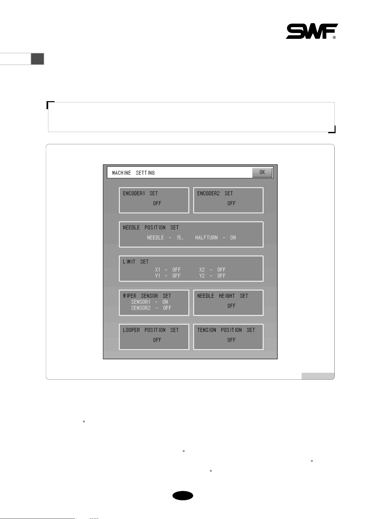
1.2 Machine Setting .............................................................................................................................................. 1-2
2.0
Function Buttons
........................................................................................................................................................ 2-1
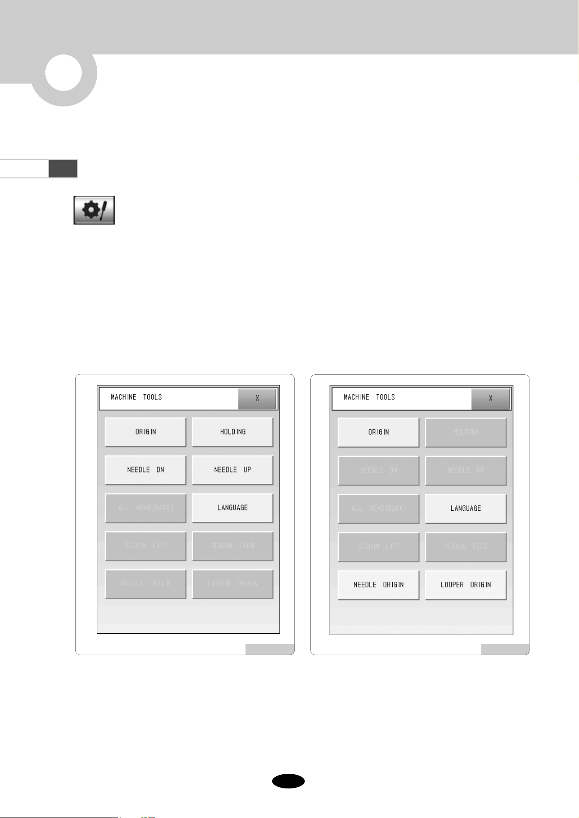
2.1.0 Tool Box .......................................................................................................................................................... 2-1
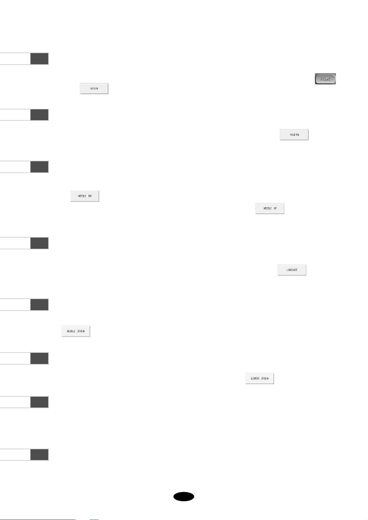
2.1.1 Origin ............................................................................................................................................... 2-2
2.1.2 Holding .............................................................................................................................................. 2-2
2.1.3 Needle DN / Needle UP ................................................................................................................... 2-2
2.1.4 Language ........................................................................................................................................... 2-2
2.1.5. Needle Origin .................................................................................................................................... 2-2
2.1.6 Looper Origin .................................................................................................................................... 2-2
2.1.7 All Head(Back) ................................................................................................................................. 2-2
2.1.8 Sequin Lift / Sequin Feed ................................................................................................................. 2-2
2.2 Needle Bar (color) Change............................................................................................................................... 2-3
3.0
Setting
............................................................................................................................................................................ 3-1
3.1 Needle (Color) Setting ..................................................................................................................................... 3-1
3.2 Chenille Setting ................................................................................................................................................ 3-5
4.0
Troubleshooting
.......................................................................................................................................................... 4-1
4.1 Error Message and Corrective Measures .................................................................................................... 4-1
4.2 Control Board Switch Setting ...................................................................................................................... 4-2
4.3 Bootloader of Thread Sensing Board ............................................................................................................. 4-7
4.4 System Block Diagram .................................................................................................................................... 4-10

11--11
①Head And Color : 3×3 HEAD , N9 C6 Color
3×3 means that the embroidery machine is a mixed type, having three heads for normal embroidery and three
heads for Chenille embroidery. N9 means it has nine colors normal embroidery and C6 means it has six colors for
Chenille embroidery.
1.1 Machine Setting Report
When installing the embroidery machine operating program, Machine Setting Report displays the information on the
embroidery machine.
After all machine setting is completed, press on the setting screen or press from the main function
menu to check the machine setting report.
To change the machine setting, see ‘3.2.0 Machine Setting Change’ of SA manual.
1
MACHINE OPERATING PROGRAM
[Fig.1.1-1]

11--22
1) Encoder 1 Set, Encoder 2 Set
Normal embroidery encoder could be set by pressing “ENCODER1 SET”. While spinning the encoder by hand, at
some point, you can hear a “beep” sound and see “ON” displayed on the screen. At this time, set the main shaft
angle at 100 and fix the encoder.
Chenille embroidery encoder could be set by pressing “ENCODER2 SET”. Just like normal embroidery encoder
setting, while rotating the encoder by hand, you can hear a “beep” sound at some point and see “ON” displayed on
the screen. At this time, set the main shaft angle at 35 and fix the encoder.
To be noted, when setting encoders, for normal embroidery, the main shaft angle should be set at 100 , but for
Chenille embroidery, the machine shaft angle should be set at 35 .
If the "Setting" button is pressed on the machine setting screen as in “3.2.0 Machine Setting Change” of SA manual,
the screen as in <Fig. 1.2-1> appears.
1.2 Machine Setting
[WARNING]
Wrong setting could cause errors to the machine. Do not change the default setting, unless you have accurate
setting information.
[Fig.1.2-1]

2) Needle Position Set
The positions of each needle bar can be set.
3) Limit Set
The limit of the frame can be set.
4) Wiper Sensor Set
5) Needle Height Set
Set the height of the needle bar of the Chenille embroidery machine at the default value. The height of the needle
bar can be set in the range from Step 1 to 10.
While rotating the potentiometer by hand, the corresponding lamp is turned on at some point. When the lamp is on,
use the wrench, set the needle bar height at Step 9, and fix the potentiometer.
6) Looper Position Set
You can set the initial looper position of the Chenille embroidery machine.
While rotating the potentiometer by hand, the OP Box issues a “beep” sound at some point. Then, choose one out of
the six loopers and fix the potentiometer.
7) Tension Position Set
You can set the initial position of the Chenille embroidery machine motor.
While rotating the potentiometer by hand, the OP Box generates a “beep” sound. Set the potentiometer at the color
change out of the four tension positions (chain stitch, loop stitch, color change and trimming positions).
11--33

22--11
2
FUNCTION BUTTONS
This is a short-cut menu to execute functions, including ORIGIN, HOLDING, NEEDLE DN, NEEDLE
UP, ALL HEAD(BACK), LANGUAGE, SEQUIN LIFT, SEQUIN FEED, NEEDLE ORIGIN, and
LOOPER ORIGIN
Press the tool box button.
If the machine is at the normal embroidery mode, and the sequin device is not installed, the screen with
five function choices, including Origin, Holding, Needle DN, Needle UP, and Language appears as in
<Fig. 2.1-1>.
In the case of the Chenille embroidery mode, and the sequin device is not installed, the screen with
four function choices, including Origin, Language, Needle Origin, and Looper Origin, appears as in
<Fig. 2.1-2>.
2.1.0 Tool Box
[Fig.2.1-1] [Fig.2.1-2]

22--22
2.1.1 Origin
This function can be used while the embroidery is not operating. It works as the “Return to Origin” on the
screen. Press to move the needle bar to the origin of a pattern.
2.1.2 Holding
This function operates the holding solenoid. It is used for normal embroidery machine. Press to activate
this function.
2.1.3 Needle Dn/ Needle Up
In order to accurately set the position of the first needle before starting embroidery, you can lower the needle bar by
pressing . After lowering the needle, you can use the direction buttons to move the frame to set the
accurate needle position. In order to return the needle to the original position, press . These functions are
available only in the normal embroidery machine.
2.1.4 Language
Nine languages including Korean, English, Spanish, German, Danish, Italian, Indonesian, Chinese, and Turkish are
supported. Users can choose a language of their convenience among the nine languages. Press and select a
desired language.
2.1.5 Needle Origin
You can return the needle bar of the Chenille embroidery machine to the origin.
Press .
2.1.6 Looper Origin
You can move the looper of the Chenille embroidery machine to the origin. Press .
2.1.7 All Head (Back)
When the thread in one of the heads breaks, but it is desired to continue the embroidery work with remaining heads,
you can use this function.
2.1.8 Sequin Lift / Sequin Feed
This function tests the sequin device after the sequin device installation is completed.

22--33
2.2 Needle Bar (Color) Change
The Needle Bar (Color) Change function enables users to change needle bars as desired. Press the button,
and the menu as in <Fig. 2.2-1> appears.
Use the “Change” button to apply change in the needle bar (color) to embroidery work, after the
change is made to the needle bar (color). The needle bar (color) is automatically changed. For
example, when currently N1 is chosen, and it is desired to change it to N5, press N5 and then the
needle bar (color) is automatically changed. When the change of the needle bar position (color) is
completed, press to confirm the setting change.
In case of the Chenille embroidery machine, change settings for new needle bar (color), stitch type
and stitch height, and press to confirm the setting change.
Buttons starting with N are used to change the needle bar (color) setting for normal embroidery. Buttons starting with C
are used to change the needle bar (color) setting for Chenille embroidery.
When changing the needle bar (color), if it is a shift between normal embroidery or between chenille embroidery, the
frame does not move. However, if it is a shift between normal embroidery and chenille embroidery, the frame is moved
by the distance between the normal embroidery machine head and the Chenille embroidery machine head.
[Fig.2.2-1]

33--11
3
SETTING
3.1 Needle(Color) Setting
For needle bar setting, press from the main function menu and select the needle bar parameter setting button.
Then, the screen for needle bar setting as in <Fig. 3.1-1> appears.
Press , and the needle bar setting screen for normal embroidery machine as in <Fig. 3.1-1> appears. On the
screen in <Fig. 3.1-2>, press and the needle bar(color) setting screen for Chenille embroidery appears.
Sets the new order of needle bars.
Changes the fixed needle bar(color) number virtually.
Marks the colors of selected needle bars(color).
Sets the needle bar(color) for normal embroidery.
Sets the needle bar(color) for Chenille embroidery. For Chenille embroidery, stitch color, stitch type and needle
bar height shall be set at the same time.
Selects the number of the needle bar(color) when setting the needle bar for Chenille embroidery.
Use the and buttons.
Selects the Chenille embroidery method. There is two way either Chain or Loop.
[Fig.3.1-2][Fig.3.1-1]

33--22
Sets the height of the needle bar for Chenille embroidery. It can be set at the range from 1 to 10.
Each step is lower or higher from the very next step by 0.3㎜.
Confirm the changed settings for Chenille embroidery.
[Fig.3.1-4][Fig.3.1-3]
[Example] Set the order of the needle bars as in the table.
①
Press to activate the number keypad and select colors for normal embroidery.
As in <Fig. 3.1-3>, the screen for needle bar selection appears. The left table of “Needle Select” shows N1.
②
Press “2” on the number keypad. As in <Fig. 3.1-4>, N2 appears on the left table of number selection (in case of
normal embroidery, needle bar selection is needed only. But in case of Chenille embroidery, embroidery type and
needle bar height should be set along with needle bar.)
STEP COLOR TYPE HIGHT
1N2
2 C3 CHAIN 3
3N5
4 C4 LOOP 5
5N9
6 C1 LOOP 8

33--33
③
Press to set the needle bar for Chenille embroidery as in <Fig. 3.1-5>. Use the and buttons to
enter the needle bar number, embroidery type and needle bar height. When the setting is completed, press
as in <Fig. 3.1-6>.
④
In <Fig. 3.1-7>, two steps are selected and you can choose the third needle bar.
[Fig.3.1-6][Fig.3.1-5]
[Fig.3.1-7]

33--44
⑤
Press . As in <Fig. 3.1-8>, press “5” to choose N5. The cursor for entry is located in Step 4.
⑥
Press . When the setting is completed as in <Fig. 3.1-9>, press to confirm the setting. The cursor for
entry moves to Step 5.
[Fig.3.1-9][Fig.3.1-8]
⑦
Set the order of needle bars as above. <Fig. 3.1-10> shows that the needle bars have been completely entered.
Check the setting details and press , if they are correct. With this, the needle bar setting has been finalized.
[Fig.3.1-10]

33--55
3.2 Chenille Setting
You can set the Chenille embroidery. <Fig. 3.2-1> shows the screen where embroidery machine option devices can be
set. Go to “8. CHENILLE SETTING” in the below figure for more details.
Select the button from the main function menu, and press the option setting button from the setting menu.
The option setting menu appears as in <Fig. 3.2-1>. On the screen, “3”, “5”, and “6” will become activated, only when
“2” and “4” are set.
Press “8.CHENILLE SETTING” in <Fig. 3.2-1>. When it is pressed, the screen as in <Fig. 3.2-2> appears. On the
first screen, press and the remaining setting menu is displayed as in <Fig. 3.2-3>.
[Fig.3.2-1]

33--66
①Max Speed
Sets the maximum speed of the Chenille embroidery machine.
- The default value is 600[rpm], and the speed can be set in the range from the minimum speed to 600 [rpm] by the
unit of 1[rpm].
②Min Speed
Sets the minimum speed of Chenille embroidery machine.
- The default value is 300[rpm], and the speed can be set in the range from 300[rpm] to the maximum speed by the
unit of 1[rpm].
③EMB Speed
Sets the embroidery speed.
- The default value is 500[rpm]. The speed can be set between Min and Max Speed by the unit of 1[rpm].
④Inching Speed
Sets the embroidery starting speed.
- The default value is 100[rpm]. The speed can be set between 50[rpm] and 200[rpm] by the unit of 1[rpm].
⑤Inching Stitch
When starting embroidery work, the machine slowly begins to operate at the inching speed. It needs to determine
the number of stitches for low-speed operation.
-
The default value is 2[st]. The number of stitches could be set at the range from 2[st] to 10[st] by the unit of 1[st].
⑥Lock Stitch
Prevents thread unravelling. If lock stitch is used, the chain stitch is made around when embroidery work is
finished by the number of stitches preset. This can prevent unraveling of threads.
- The default value is zero, and the value can be set in the range from 1 to 10 stitches by the unit of one stitch.
[Fig.3.2-3][Fig.3.2-2]

33--77
⑦
Thread Break Sensor
Thread break can be regularly checked by setting the number of stitches for break check. When the pre-defined
number of stitches reaches, the machine checks whether thread break occurs.
- The default value is zero and it can be set in the range from 1 to 10 stitches by the unit of one stitch. If this
function is not going to be used, set the function at Disable (0).
⑧
Select Trim Mode
Chooses between the loop trimming mode and the chain trimming mode. The loop trimming mode performs
regular trimming, such as thread cutting. The chain trimming mode performs trimming and then threads the needle
and tightly fixes the thread.
- The default value is “Loop”. To shift to regular trimming, press “1” and then “confirm.”
⑨
Auto Frame Change
N/A
⑩Taping Function
This function helps set up the taping device. When the taping device is installed, this function becomes abled. If it
is not installed, this function is disabled and unable to use.
- The default value is “NO”.
⑪Auto Start After Backstitch
This function helps determine whether to activate automatic start after backstitch.
- The default value is “Yes”. If automatic starting is not desired, enter “0” to disable this function.
⑫Start Point After Backstitch
This function helps set up the initial motion position of the entire needle bar from the stop position after backstitch
is conducted.
- The default value is 1[needle]. The value can be set at the range from 1 to 20[needle].

44--11
4
TROUBLESHOOTING
4.1.0 Error Messages and Corrective Measures
Error MessageNo.
900
Chenille Main Shaft is not at the
Fix Position.
The main shaft does not stop at
35°.
Use the lever to set the main shaft
angle at 35°.
901
ID Check failure of chenille
board.
The control board ID setting was
wrong or communication
conditions are bad.
See “4.2 Control Board ID
Setting” to check the ID of each
control board.
910
Initialization failure ARM board.
Error has occurred in the middle
of initializing the ARM control
board.
Turn on or off the power. If
problems continue to occur, call
the nearest A/S service center.
911
Rotation failure of Needle motor.
The rotating motor of the needle
bar of the marked head develops
error while spinning.
Turn off the power and manually rotate the
needle bar to check any problems. After
checking is done, turn on the power again.
912
Origin failure of Needle motor.
The rotating motor of the needle
bar of the marked head did not
turn to the origin.
Turn off the power and rotate the needle bar
by hand to see if there is any problem. After
checking is done, turn on the power again.
913
Frame transfer failure by needle
height
This error could occur when the needle bar is
located below the frame, when the frame moves.
Perform manual trimming.
920
Initialization failure of BASE
board
This error could occur in the middle of
initializing the BASE control board.
Turn off and on the power.
921
Rotation failure of Looper motor
This error could occur, while the
looper rotating motor of the
marked head is in action.
Turn off the power and rotate the looper by
hand to see if there is any problem. After
checking is done, turn on the power again.
922
Origin failure of Looper motor
The looper rotating motor of the
marked head did not return to the
origin.
Turn off the power and rotate the looper by
hand to see if there is any problem. After
checking is done, turn on the power again.
923
Origin failure of trim mes The trimming mes did not return
to the origin.
Turn off the power and open the needle plate to
see if there is any problem in the trimming mes.
924
Looper position error The looper is located at the wrong
place.
Turn off the power and adjust the
looper’s position.
925
Chenille color change error The color change was not
accurately handled.
Turn off the power and adjust the
looper’s position.
914
Failure of the needle bar height
adjusting
Time lapse error during needle bar
height adjustment
Potentia meter setting check for
needle bar height adjustment or
motor connection status check
990
Communication with sub board
failed
The communication between the
OP Box and the control board is
not proper.
Turn off the power and turn it on
again. Or check the dip switch of
the control board.
Description Corrective Measure

44--22
4.2 Control Board Switch Setting
The Chenille embroidery machine is controlled by the Control Board. It means that ID setting for each board should be
accurate. The following figures show how to set the dip switch ID depending on head, arm and base. If any
communication errors occur, keep in mind the following settings to check the errors.
1) Dip Switch (SW2) and Rotary Switch (SW1) Setting for Control Box
- Position of Control Board Switch
[1~2 Head] [3~4 Head]
[Arm Side] [Arm Side]
[Base Side] [Base Side]
Power Input
Dip Switch
SW2 SW1
ON
SW2 SW1
ON
4
3
2
1
4
3
2
1
SW2 SW1
ON
SW2 SW1
ON
4
3
2
1
4
3
2
1
Rotary Switch
SW3
SW4
SW1
SW2 CN14
SW7
SW5
SW6
SW10
SW8
SW9
Step Motor Driver1 Dip Switch
Step Motor Driver1 Rotary Switch1
Step Motor Driver1 Rotary Switch2
Step Motor Driver1 Rotary Switch3
Step Motor Driver2 Dip Switch
Step Motor Driver2 Rotary Switch1
Step Motor Driver2 Rotary Switch2
Step Motor Driver2 Rotary Switch3

44--33
[5~6 Head] [7~8 Head]
[Arm Side] [Arm Side]
[Base Side] [Base Side]
SW2 SW1
ON
SW2 SW1
ON
4
3
2
1
4
3
2
1
SW2 SW1
ON
SW2 SW1
ON
4
3
2
1
4
3
2
1
[Tape Side] [Tape Side]
SW2 SW1
ON
SW2 SW1
ON
4
3
2
1
4
3
2
1
[Tape Side] [Tape Side]
SW2 SW1
ON
SW2 SW1
ON
4
3
2
1
4
3
2
1

44--44
[9~10 Head] [11~12 Head]
[Arm Side] [Arm Side]
[Base Side] [Base Side]
SW2 SW1
ON
SW2 SW1
ON
4
3
2
1
4
3
2
1
SW2 SW1
ON
SW2 SW1
ON
4
3
2
1
4
3
2
1
[Tape Side] [Tape Side]
SW2 SW1
ON
SW2 SW1
ON
4
3
2
1
4
3
2
1
Dip Switch Rotary Switch
Other manuals for SWF Series
1
Table of contents
Other Sunstar Precision Sewing Machine manuals
Popular Sewing Machine manuals by other brands

Singer
Singer 457UX143 Service manual

Singer
Singer 246-5 parts list

Janome
Janome Horizon Memory craft 7700 QCP manual

Pfaff Industrial
Pfaff Industrial PowerLine 2595 Adjustment manual

Pfaff
Pfaff CREATIVE VISION - V13598 UPDATE CREATIVE VSION SEWING AND EMBROIDERY... Update

Singer
Singer 8770 CURVY Features & benefits