Gammill Vision User manual

Page 1
User Manual
Copyright © 2010 Gammill, Inc. All Rights Reserved

Page 2
Gammill Vision™ User Manual
__________________________________
IMPORTANT MACHINE INFORMATION
It is our goal to ensure that Customers have information on the tools and accessories
(standard and optional), that are available for use with Gammill® quilting machines.
Some of the tools and accessories detailed in this Manual may be optional equipment.
We recommend that you consult with your Authorized Gammill Dealer or Sales
Representative for the most current list of standard and optional equipment. Standard
equipment, optional equipment, and pricing are subject to change without notice.
Copyright © 2010 Gammill, Inc. All Rights Reserved
Publish Date: February 2010
All rights reserved. No parts of this work may be reproduced in any form or by
any means – graphic, electronic, or mechanical, including photocopying,
recording, taping, or information storage and retrieval systems – without the
written permission of the publisher.
Products that are referred to in this document may be either trademarks and/or
registered trademarks of the respective owners. The publisher and the author
make no claim to these trademarks.
While every precaution has been taken in the preparation of this document, the
publisher and the author assume no responsibility for errors or omissions, or for
damages resulting from the use of information contained in this document or
from the use of programs and source code that may accompany it. In no event
shall the publisher and the author be liable for any loss of profit or any other
commercial damage caused or alleged to have been caused directly or indirectly
by this document.
Our thanks to Pat Barry for writing this manual, and Alan Barry for many of the pictures.

Page 3
Table of Contents
Section 1 - Tour your Gammill Vision™......................................................................................................... 6
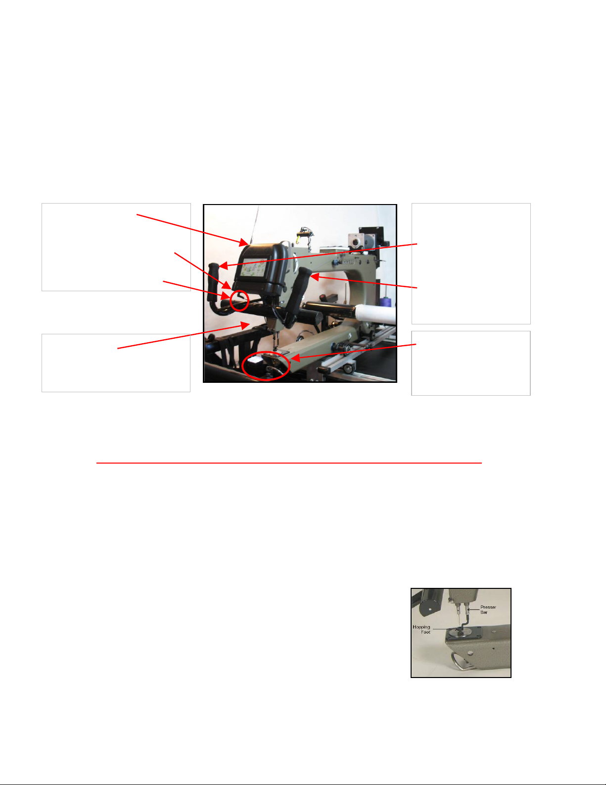
Gammill Vision™ - Front View ....................................................................................................................... 6
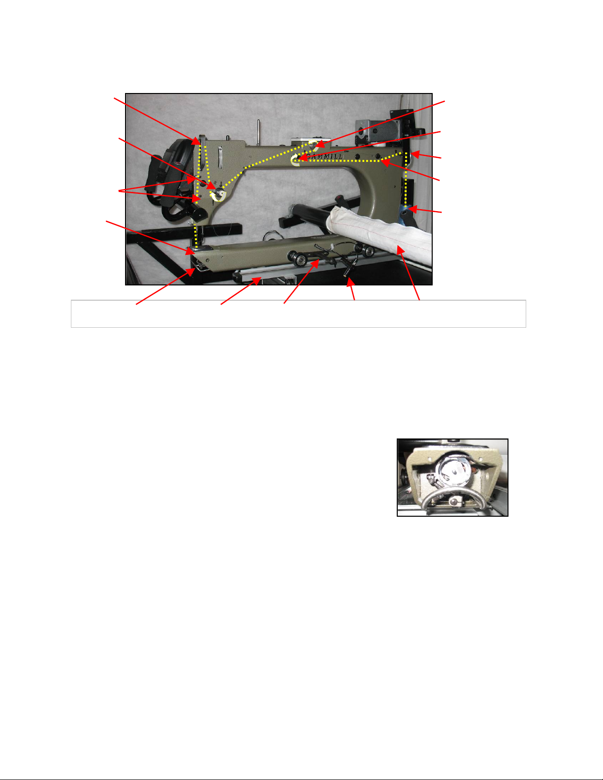
Gammill Vision™ - Right SideView ................................................................................................................ 7
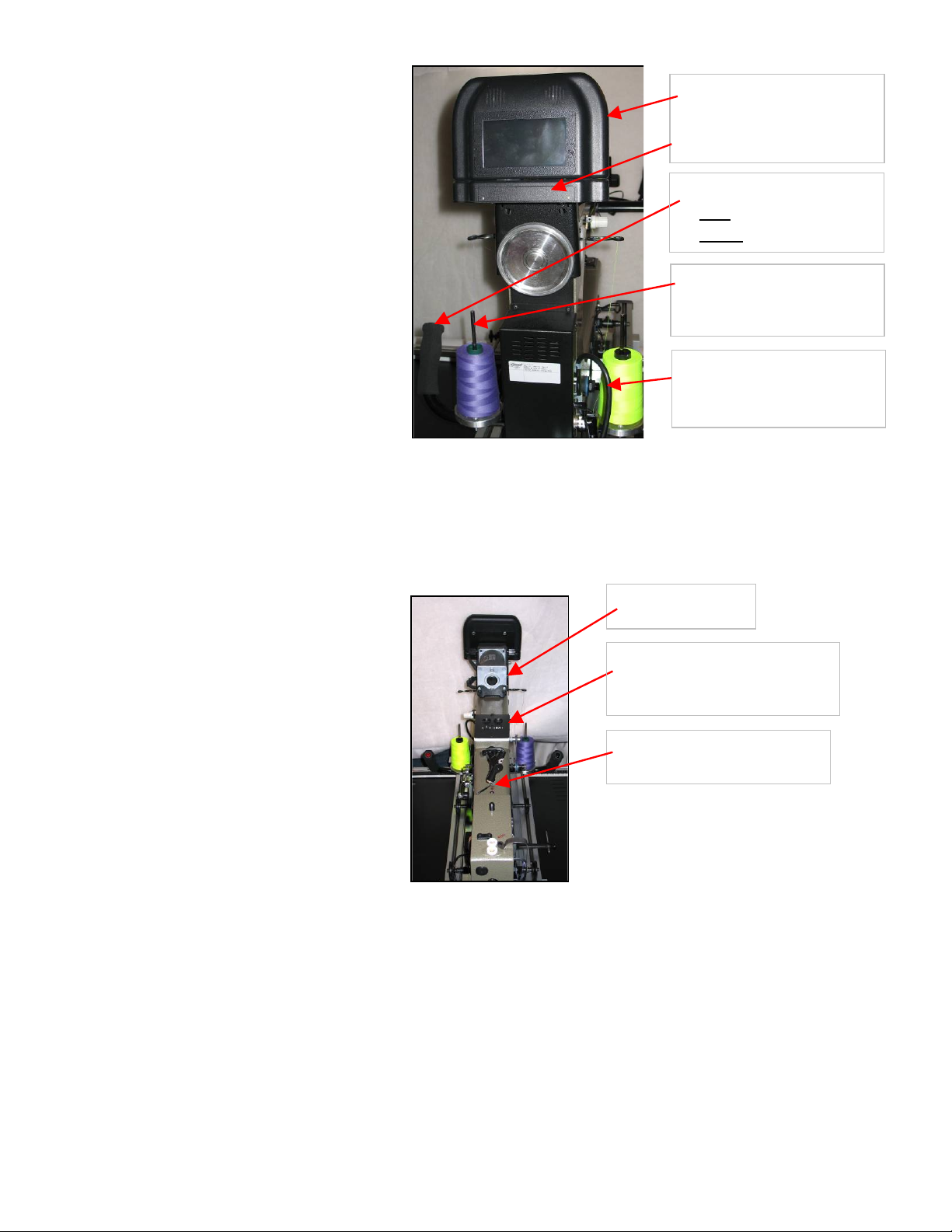
Gammill Vision™ - Left Side View ................................................................................................................. 8
Gammill Vision™ - Back View ....................................................................................................................... 9
Gammill Vision™ - Top View ....................................................................................................................... 10
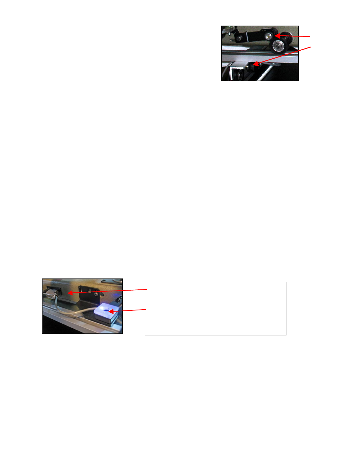
Gammill Vision™ - Bottom Crosstrack (aka Carriage)................................................................................. 11
Tour Your Table ........................................................................................................................................... 12
GS-1PA Table.......................................................................................................................................... 12
Home-Pro Table ...................................................................................................................................... 13
Section 2 – Getting Ready to Quilt ............................................................................................................... 13
About the manual ................................................................................................................................ 13
About the instructions.......................................................................................................................... 13
Threading the Machines .............................................................................................................................. 13
Back Section............................................................................................................................................ 14
Middle Section ......................................................................................................................................... 15
Front Section ........................................................................................................................................... 16
Threading the Gammill Vision™ 18-8...................................................................................................... 17
Using the On-board Bobbin Winder ............................................................................................................. 17
Winding bobbins while quilting................................................................................................................. 18
Winding bobbins before quilting............................................................................................................... 18
Using a Stand-alone Bobbin Winder ............................................................................................................ 19
About the Bobbin Case ................................................................................................................................ 19
Inserting the Bobbin Case ....................................................................................................................... 20
Setting the Tensions .................................................................................................................................... 20
Set the Intermittent Tension..................................................................................................................... 20
Set the Rotary Tension ............................................................................................................................ 21
Set the Bobbin Case Tension .................................................................................................................. 21
Checking the Top Thread Tension ...................................................................................................... 21
Changing the Top Thread Tension...................................................................................................... 22
Section 3 - Navigating The Screens ............................................................................................................. 23
Turning on (and off) the machine................................................................................................................. 23
Initialization:......................................................................................................................................... 23
Main Screen - Carousel of Patented Applications ....................................................................................... 24
Stitcher Modes......................................................................................................................................... 24
About the Stitch-regulator - ................................................................................................................. 24
Channel Locks ......................................................................................................................................... 25
Stitch Monitor ...................................................................................................................................... 26
FM Tuner ................................................................................................................................................. 28
Tools / Diagnostics .................................................................................................................................. 29
Settings / Preferences ............................................................................................................................. 30
Main Screen - Settings................................................................................................................................. 30
Main Screen - Setting Changes............................................................................................................... 30
Main Screen - Status Information ................................................................................................................ 32
Stitcher Status Button .............................................................................................................................. 32
Needle Positioner .................................................................................................................................... 33

Page 4
Laser Light ............................................................................................................................................... 33
Automatic Tie-offs.................................................................................................................................... 34
Stitch Counters ........................................................................................................................................ 34
Bobbin Factor Icon .............................................................................................................................. 35
Bobbin Fill Gauge ................................................................................................................................ 35
Stitch Counter Icon.............................................................................................................................. 36
Run-time Clock Icon. ........................................................................................................................... 37
Section 4 - Let’s Quilt ! .................................................................................................................................. 38
Standard Procedures ................................................................................................................................... 38
Pull up the bobbin .................................................................................................................................... 38
Tie-off Stitches to Begin........................................................................................................................... 39
Continuous Line Designs......................................................................................................................... 39
Tie-off to End ........................................................................................................................................... 39
Trim.......................................................................................................................................................... 39
Explore Stitching Modes ................................................................................................................................. 40
Regulate ................................................................................................................................................. 40
Coast Regulate....................................................................................................................................... 40
Constant ................................................................................................................................................. 41
Baste ...................................................................................................................................................... 41
Explore the Settings / System Preferences ................................................................................................. 42
Laser Light ................................................................................................................................................42
Response..................................................................................................................................................42
Coast Spread............................................................................................................................................42
Coast Threshold .......................................................................................................................................42
The 4th scale .............................................................................................................................................43
System Alarms......................................................................................................................................... 43
Thread Break Alarm ............................................................................................................................ 43
Too Fast Alarm.................................................................................................................................... 43
Bobbin Empty Alarm............................................................................................................................ 43
Turning Off Alarms .............................................................................................................................. 44
Needle Positioner .................................................................................................................................... 44
System Volume........................................................................................................................................ 45
Calibration................................................................................................................................................ 45
Section 5 - Quilting Techniques.................................................................................................................... 47
How To Relocate the Screen ....................................................................................................................... 47
How To Start and Stop (a line of stitching) .................................................................................................. 48
How To Restart (a line of stitching).............................................................................................................. 48
How To Test the Tension............................................................................................................................. 49
Adjust the bobbin tension .................................................................................................................... 49
Adjust the top thread tension............................................................................................................... 50

Page 5
Congratulations on the purchase of your new Gammill Vision™ Quilting System.
Gammill has added high tech electronics to its ‘Best of Class’ stitching mechanism,
giving you an exceptional quilting experience!
The new features incorporated into the Gammill Vision™ are a result of suggestions from
current customers plus Gammill’s dedication to providing the best quilting system possible to
meet your needs. The Gammill Vision™ is complete with options that enable you to adjust the
stitching to suit your style.
The first and most obvious improvement is the touch screen, which displays the color icons for
all of the features. Operating instructions are easier to find and understand using the new
icons. What isn’t as obvious are the technological improvements behind these features. The
new technology enables you to easily learn, use, and maintain your new quilting partner. It
also allows you to update your system as new and exciting features are added in the future.
There is a new ‘Coast’ mode that combines the stitch-regulator with constant speed for
efficient transition to micro-stitching. The stitch-regulator operates at higher speeds, but the
machine automatically switches into constant speed when the machine speed drops below the
adjustable Coast threshold. This enables you to stitch motifs using the regulator, and
automatically switch to constant speed to micro-stipple the background.
We still offer the ‘Regulated’ mode but now you can adjust it to fit your speed. High-speed
quilters are prone to getting the occasional long stitch at take-off points. Slow-speed quilters
may see extra stitches in the points. Regardless of your speed preference, you can now easily
set the regulated mode response to adjust the stitching to suit your speed.
Another step toward trouble-free quilting is the optional digital video camera. Turn on your
camera and see the stitch quality on the underside of the quilt. No more flashlights and mirrors!
There are other self-diagnostic checks occurring while you are stitching. They are happening in
the background so they don’t disrupt your stitching unless a warning is needed. The early
warning system is a true time saver.
Thank you for choosing the Gammill Vision™ – we are sure you will enjoy it!
Please read this manual before operating your new machine, even if you have used a Gammill
Quilting System before. There is some new information that will make your quilting experience
easier, and you don’t want to miss it.

Page 6
Section 1 - Tour your Gammill Vision™
This chapter is dedicated to introducing the Gammill Vision™, and some new terminology.
Some terms will be familiar and some will be new, but if you understand the terms, the
explanations included later in this manual will make more sense. Consider this section an
overview; complete instructions are in later sections.
Gammill Vision™ - Front View
Here is a picture of your state-of-the-art Gammill Vision™.
1. Main Module – displays all the instructions and icons. The Main Module is actually a separate
module that fits into a docking station that is attached to the machine. There is a docking station at the front
and at the back of the machine, so the module can be moved to the back of the machine when doing
pantographs.
Caution: Be sure to have the power off when moving the module from one end to the other.
2. Handles – there are two handles in the front and in the back, and they function the same
way. In the left handle is the Single Stitch button that controls the single stitch and needle position functions. In
the right handle is the Run button that controls the starting and stopping of the stitching. Often the right button
is red and is called the Red button.
3. Light Bar – there is a long thin light fixture attached to the handles. The light switch is on the right
side, hidden by the black guard. Flip the switch away from you to get natural light (LED). Flip it toward you to
turn on the black light (UV) which is very helpful when using glow-pencil markers or when quilting with white
thread on white fabric.
4. Needle Area – The needle bar holds the needle in place.
The hopping foot is a circular guard that surrounds the
needle. The hopping foot is more than just a safety guard. It is
instrumental in creating a good stitch, and it also allows the use of
templates and rulers. The shape makes it safe to guide the machine
along the edge of a template or ruler for a perfect stitch line or design.
The camera also helps insure a good stitch.
Needle area in front
1. Main Module
with antenna
Front Docking Station
Laser Light Plug
2. Handles:
Left handle button
is Single Stitch
Right handle button
is the ‘Run’ button to
Start/Stop stitching
3. Light Bar
Light Bar switch is underneath
on the right. (UV, off, LED)
4. Needle Area
with optional
Camera

Page 7
Gammill Vision™ - Right SideView
The right side of the Gammill Vision™ has the threading path and tension devices.
1. Thread Path – Threading the machine can seem complicated but it is actually easy because
the thread guides clearly mark the path. In this example, thread comes off the cone, going straight up
into the first guide called the thread lead-off. There are two more guides that take it into the intermittent tension
assembly, and it is wrapped around the silver cylinder (which is a thread break sensor wheel) and then to
another guide and to the rotary tension assembly. Two ‘L’ shaped guides help keep the thread in the check
spring. From there it goes to the take up lever, through more guides and finally through the eye of the needle.
Detailed threading instructions are given in the following pages.
2. Bobbin Area – is the open area below the needle. The bobbin
and bobbin case are larger than most domestic sewing
machines so they hold more thread, and run out less often.
The sewing hook (also known as hook race or hook) spins around the
bobbin, catching the thread and making the stitch. Be sure nothing ever
obstructs this motion. This area will look familiar very soon since you will
clean the bobbin area with a small brush every time the bobbin is
changed. .
3. Crosstrack – Also known as the carriage, is a platform that holds the machine. It has two
tracks so the machine can roll front-to-back. It sits on two tracks on the table which allow it to roll left to right.
The crosstrack has the vertical channel lock attached as well as one of the encoders for the stitch-regulator.
4. “T” Bar is a bracket shaped like a ‘T’ that is screwed into the side of the machine. The bracket
can hold the stylus vertically when it is being used to align the machine with a mechanical template like the
WorkStation or the Design Center. The bracket can also hold the stylus horizontally for attaching the adjustable
laser clamp when it is being used to hold the laser light while stitching pantographs.
5. Laser Light – is being held in a special clamp that allows it to be turned so it points in
virtually any direction. When attached to the ‘T’ bracket, as shown here, the laser light is used to follow
pantographs which are stitched from the back of the machine. When using the laser light at the back, plug it
into the Power Enclosure on the left side at the back of the machine. It only fits in one place on the Power
Enclosure. The laser light and clamp can also be moved to the front for use when working at the front of the
machine, as shown in the next paragraphs.
2. Bobbin Area, 3. Crosstrack, 4. “T” bracket, 5. Laser light, 6. Pickup roller
Take-up Lever
(behind guard)
Rotary Tension
(the check spring is
inside)
Thread Guides
Needle Area
Thread Break Sensor
Intermittent Tension
Thread Lead-off
Thread Guide
Cone thread

Page 8
6. Pick Up Roller – will hold the quilt layers after they are quilted. It must be located inside the throat
space to ensure the machine can move freely. It starts out small – taking just a few inches but as the quilt
nears completion, the size increases and this reduces the amount of quilting space left free for stitching.
Gammill Vision™ - Left Side View
The left side of the Gammill Vision™ has an on-board bobbin winder.
1. Bobbin Winder – How convenient it is to wind bobbins while you stitch so they will be
ready when you need the next one! The bobbin winder has a thread path, which travels from the
cone of thread, up through the guides, through the tension assembly and over to the bobbin. The bobbin
sits on a post that will spin when the machine is stitching. The bobbin winder lever is lowered into the
bobbin. As the bobbin fills, the lever is pushed up and will eventually pop up, stopping the bobbin winder
from turning.
2. Laser Light – has been moved from the back of the machine to the front. It is still being
held by the adjustable laser clamp that allows easy adjustments, but now it is attached to a post on the
top of the machine. In this position, it is easy to follow stencils and block patterns. The light plugs into the
bottom side of the front Docking Station and the wire is held by the white clips, preventing it from touching
the front hand wheel.
This close-up picture shows the
Camera bracket (attached)
and
Camera assembly (plugged in).
Plug in H Channel lock. 5. Vertical Channel lock
4. Horizontal Channel lock. and its plug
3. Encoder for stitch-regulator 6.Camera connection
6. Camera connection
2. Laser Light with
adjustable laser clamp
Front hand wheel
Laser light front plug
Clips (to hold laser light wire
away from the hand wheel.)
1. Bobbin Winder
Tension Assembly
Thread Lead-off
Bobbin Winder Lever
Bobbin
Power Enclosure
Thread Cone

Page 9
3. Encoder – The stitch-regulator has two encoders that
‘ride’ the wheels and measure how fast the machine
is moving and in which direction, so it knows when to
make the next stitch. The encoder riding the wheel on the
machine monitors the Vertical movement (front to back). There is
another encoder that is located on the underside of the
crosstrack that monitors the horizontal movement (side to side).
Between these two encoders, the stitch-regulator can determine
when to stitch.
4. Horizontal Channel Lock – is a magnet attached to the side of the machine that locks
onto the crosstrack preventing it from moving forward and backward, hence the
Horizontal lock. The channel lock is set on and/or off by touching the icon on the screen.
The lock plugs into the adjacent electrical plug on the side.
5. Vertical Channel Lock – is a magnet attached to the front of the crosstrack that locks
onto the table preventing it from moving side to side, hence the Vertical lock. The
channel lock is set on and/or off by touching the icon on the screen. The lock plugs into
a wire connection at the front of the crosstrack. This cable at the back of the crosstrack
plugs into the right side of the Power Enclosure.
6. Camera connection – The larger of the two electrical plugs is for the camera connection.
Each plug has a unique shape so it can only fit in one place.
Camera Assembly
The camera assembly is held in place by a bracket that screws into the side of the
machine. It takes a video image of the under side of the quilt so you can examine the stitch
quality on the back. The camera also has both LED (white) lights and UV (black) lights to
help you see the stitches on the back of the quilt. The bracket looks like it is touching the
crosstrack, but it is not.
Gammill Vision™ - Back View
The machine can be operated from either the front or the back. All handle buttons remain active
regardless of the Main Module’s location.
1. Main Module and the rear
Docking Station. The screen can
be moved to the back dock very
easily, as shown. Lightly pull it straight
up to remove and reverse to install.
Camera assembly is plugged in, and the
lights are on.
The camera lens is in the middle.
The image will be displayed on the screen.
Encoders:
Vertical
Horizontal

Page 10
2. Handles on the back operate
just like the handles on the
front; The Single Stitch button is in
the left handle and the Run button is
in the right handle.
3. Vertical Spool Holder Extension
– is 4" long, and is located on top
the regular spool holder. It is used for
small spools or cones of cross-wound
thread.
4. Power Enclosure, cords, and
connectors - Each of the cords can
connect in only one spot, so getting
the machine plugged in is easy.
Gammill Vision™ - Top View
The top of the machine contains the power switches and more.
1. Motor - is mounted toward the
back of the machine. The motor
turns a belt which has a black plastic
covering for safety.
2. Power and Motor Switches are
mounted in the middle. They can
easily be reached when standing in the
front or the back of the machine. Turn
power on first, then motor.
3. Post - In front of the switches is the
post for the laser light. This is where
the laser is attached when working at the
front of the machine.
3. Post for laser mount
1. Motor
2. Power and Motor
switches
1. Main Module
(at rear)
Rear Docking Station
2. Handles & buttons
Left is single stitch
Right is Run
4. Power Enclosure
cords and connectors
3. Vertical Spool Holder
Extension
The Vision™ uses standard household current (110, grounded).
A high quality surge protector is recommended to protect your
investment.

Page 11
Gammill Vision™ - Bottom Crosstrack (aka Carriage)
Each machine has a special platform called a crosstrack or carriage, which allows the
machine to move freely around the table. The crosstrack has channel locks which use
magnets to stop the machine from moving. It also has encoders that detect and measure
motion which is an important element of the stitch size regulation. The machine’s wheels fit
into tracks on the crosstrack, enabling the machine to move front to back. The crosstrack’s
wheels fit into tracks on the table, enabling it to move side to side.
Tracks (also called rails) are specially designed to allow the wheels to move smoothly. There
are two tracks on the crosstrack (for the machine’s wheels) and two tracks on the table (for the crosstrack’s
wheels).
3. “H” and “V”
Channel locks
(See Page 9)
2. “X” and “Y”
Encoders
(See Page 9)
1. Tracks

Page 12
Tour Your Table
The Gammill Vision™ is available in three sizes; V18-8, V26-10, V30-12. The first number is
the distance in inches from the needle to the back of the throat area, and the second number
is the height of this space. The tables used for the Gammill Vision™ are the same as the
tables used for the same size Plus (stitch regulated) or Standard (non-stitch regulated)
machines.
The V18-8 is paired with the Home-Pro table, which is available in 10’ and 12’ lengths. The
V26-10 and the V30-12 require the GS1 table. The standard size for the GS1 table is 12’ but
custom lengths are available.
GS-1PA Table
This close-up picture shows the right side of the table, with many of the parts labeled.
1. The PA Assembly is incredibly useful! It can be released (just pull out the pivot pin) so it
can pivot the top roller up, exposing the batting and backing layers. This is very useful for
removing stray threads and smoothing the batting layer.
2. It has two fixed positions; Quilt and Load. When in Quilt position, the PA assembly is
slanted back, making it comfortable to sit while quilting. The picture shows the quilt position. In
load position, the PA assembly is vertical, not slanted, which makes the quilt layers easier to load. To
switch from one to the other, remove the pivot pin, reposition the PA assembly and re-insert the pin.
Leaders are strips of canvas that are attached to
three rollers; Pickup roller, Backing roller and the
Top roller.
The layers of the quilt will be attached to the canvas
leaders using pins, zippers, hook & loop tape, or even
plastic staples!
When fabric is loaded, these three rollers hold it
taut using locking levers (dogs) that fit into the
gear shaped end of each roller, near the hand
wheel.
This picture shows the right side of the table from a
different perspective.
1. The Pivotal Access (PA) Assembly consists of the
metal bar holding the three rollers
Top roller (with the hand wheel)
Stabilizer bar
Carrier bar (or belly bar).
2. Also shown is the pivot pin, and the two pivot
pin holes which control the angle of the assembly.
Quilt Position
Load Position
GS1 Table Parts

Page 13
Home-Pro Table
The Home-Pro table is perfect for home use
and has a very sturdy metal frame. The
rollers, leaders, table top and crosstrack all
function in the same way as the GS-1PA table.
Section 2 – Getting Ready to Quilt
Now that you have been introduced to your new Gammill Vision™ quilting system, it is time to
get ready to quilt. The previous section defined many new terms – most of them were names
for the various parts of your quilting system. There will be more new terms, but since you know
the names of the machine parts, the new terms will make more sense.
About the instructions
The following sections provide step-by-step instructions and lots of good tips.
•Instructions are either numbered or listed as bullet points.
•Each set of instructions might be prefaced with a paragraph of ‘Prep Steps’ so you know
what needs to be done before you start the process.
•Often the instructions have some tips or suggestions that are printed in a smaller font.
•‘Your Turn’ means you should take a few minutes and try the exercise.
•Many instruction sets are followed by a paragraph entitled ‘Beyond the Basics’ which
introduce alternative methods or techniques that you might want to try in the future.
As you grow in experience and exposure, you are sure to find different methods of performing
basic quilting techniques. There are certainly many ways to do these techniques and the ones
described here are (hopefully) simple and clear.
Threading the Machines
Now that you have taken a quick tour of your new quilting system, it is time to thread the
machine. There may still be some new terminology, but the text and pictures should help
define them.

Page 14
The Gammill Vision™ 26-10 and 30-12 have the same thread path. The V18-8 is a little bit
different as we will see later in this section. Complete details are given by area, beginning with
the cone of thread at the back of the machine and working forward. Enlarged areas are often
photographed from a different perspective so the details will be shown more clearly.
Back Section
1. Draw some thread off the cone. Take it
straight up and into the first thread guide called
the thread lead-off.
Thread is wound onto a cone in a crisscross
method and needs to have it drawn off by
pulling the thread straight up so it does not twist.
2. Follow the twist of the metal and put the
thread through the second eyelet in the guide,
from the back to the front. See the enlarged
diagram.
3. The thread goes through another guide a few
inches forward.
Looking at the thread
lead-off from
behind shows it has
two eyelets.
Front Middle Back
Middle
Back

Page 15
Middle Section
4. Bring the thread forward and through the thread
guide that is attached to the intermittent tension. If
this assembly were a clock, the thread guide
would be positioned at about 3:00.
When the stitcher is running, the intermittent
tension actually moves in and out about 1/32”.
This action is intended to add tension at just the
right time to aid in pulling the thread up from the
bottom of the quilt. This action makes it harder to
pull thread from the thread spool and easier to pull
thread from below the quilt, preventing loops. This
is a patented feature on the Gammill Vision™ 26-
10 and the Gammill Vision™ 30-12 (the Gammill
Vision™ 18-8 does not have this stroking feature
on the intermittent tension).
5. Wrap the thread clockwise around the tension
assembly once (which is really about 80% of the
way). The thread should fit inside the two blue -
gray tension disks.
Be sure the thread always stays between these
two disks because when it slips out, the under side
of the quilt will have poor tension. If the tension is
too tight, the thread will quickly work its way out of
the disks.
6. Bring the thread back to the thread break sensor and wrap it counterclockwise 1 ¾
turns. The thread will sit inside a “V” shaped track. This sensor turns when the machine is
stitching. If it stops turning for 50 stitches,
the Thread Break Alarm will sound.
.
Sometimes the Thread Break Alarm will
sound even if the top thread has not
broken. Stiff or slippery thread can slip out
of the track. Running out of bobbin thread
can also cause the alarm to sound.
7. Pull the thread forward to the next thread guide, bringing it down through the first hole and
up through the third hole.
5. Looking at the intermittent tension from
behind shows the thread guide, adjustment
knob, tension spring and the thread nestled
inside the two blue / gray tension disks.
Note: The Intermittent Tension Baseline setting
is when the adjustment knob is flush with the
inside threaded shaft.
Adjustment Knob
Tension spring
Tension disks
4. Thread guide
7. From guide toward
Rotary Tension.
6. Around Thread Break
Sensor 1 ¾times

Page 16
Front Section
8. Bring the thread down, over the Top (right angled) bracket.
9. Wrap the thread around the rotary tension assembly 1 3/4 in a
clockwise direction, making sure the thread stays in the “V” shaped
track. The thread path is not quite two full rotations.
11. Bring the thread back down and under the Bottom (angled) bracket. As you pull on the
thread, the check spring will move from about 10:30 to 9:00 position, and back.
12. The thread then goes through the eyelet in the take-up lever (hidden behind the guard)
from back to front.
13. Bring the thread down, through the remaining thread guides.
14. Thread the needle, from front to back.
Beyond the Basics -
Tip for easy thread changes – When you need to change the thread, don’t pull the current
thread out and rethread using the new color. Instead, go to the back of the machine and cut
the thread even with the top of the cone. Remove the original cone and replace it with the new
color. Draw off some thread from the new cone, and securely tie the ends of the two colors
together. Now, go the front of the machine, take the thread out of the needle, and pull on the
thread until the new color is in place. Cut off the knot and rethread the needle.
Important! Check that the new color thread is still securely tucked into the intermittent tension
disks and that it is still in the track around the thread break sensor, and rotary tension
assembly.
Top bracket
Check spring
Bottom bracket.
“V” Thread track
Tension spring
Adjustment knob
Threaded Shaft
Looking at the rotary tension from above shows the
brackets, guides and check spring.
10. Guide the thread up far enough so it catches the wire of
the check spring. The check spring has a ‘U’ shape, and it moves a
bit. Gently move the check spring down and forward to make it easier
to get the thread into the ‘U’ shape.
Note: The Rotary Tension Baseline setting is when the adjustment
knob is flush with the inside threaded shaft.

Page 17
Threading the Gammill Vision™ 18-8
Threading the smaller, V18-8 machine is virtually the same.
Using the On-board Bobbin Winder
This feature allows you to wind bobbins either
while you are quilting, or not. The bobbin
winder uses its own cone (or small cone) of
thread, so if you have two cones of the same
color, you can wind bobbins while you quilt. If
you don’t have two cones of the same color,
you can wind bobbins before you begin to
quilt.
1. Draw some thread off the cone on the left side of the
machine. Just like before, take it straight up and into the first
thread lead-off guide.
2. Follow the twist of the metal and put the thread through
the second eyelet in the lead-off guide, from the back to the
front.
3. The thread goes through another guide a few inches
forward.
4. The thread must go under the tension disk and through the guide on the other side. Don’t
wrap the thread around the tension disk. Keep the thread in the lower half only. Sometimes it
Go ahead and thread the machine. Pay special attention to how the thread fits
into the tension assemblies. Rotate both tension knobs until they are flush with
the screw they surround. This is the normal ‘Start’ position for all tension
adjustments. Pull on the top thread, and notice the resistance – that is good!
Your
Turn
There is one extra thread guide in the front, however.

Page 18
is easiest to thread the first tension disk guide, then the second, and pull a loop around to the
bottom of the tension disks, and then pull on the thread from both sides to get the thread to
pass between the tension disks.
5. Bring the thread forward through the next thread guide and
up to the on-board bobbin winder.
Winding bobbins while quilting
1. Place an empty bobbin on the bobbin winder spindle. There
is a little wire spring on the end of this spindle that will hold the
bobbin in place. If you look closely at an empty bobbin, you will
see a small notch on the inside edge.
2. Don’t try to align the wire with the notch. Just push the bobbin onto the spindle and then turn
the bobbin until it clicks into place.
3. Wrap the thread clockwise around the center of the bobbin 6-8 times, securing the end.
4. Push the bobbin winder arm down. It will slide to the inside of the bobbin. Now, bring it back
up about ¼”, so it is not touching the center of the bobbin.
5. Now, when you begin to quilt, the bobbin will wind. When the bobbin is full, the arm will pop
up and the bobbin will stop revolving.
The bobbin should not be soft and mushy, but it also should not be so tight that you can’t feel a
little give when pressing on the thread with your fingernail.
Winding bobbins before quilting
If you need to wind bobbins before you begin to quilt, you will be running the machine from the
Diagnostics screen.
Detailed instructions for using the Diagnostics are in the next section, so don’t worry if you
don’t understand the following steps yet – You will!
1. Load an empty bobbin as described above.
2. Be sure the bobbin case is not in the machine.
3. Remove the thread from the needle and take-up lever.
Wrap it around the foam covering of one of the handles. This prevents tangling.
4. Choose Diagnostics from the Initial Screen carousel.
5. Change the speed setting to about 30-50%.
6. Start by pressing the red button in the Upper Left Corner of the screen.
7. When the bobbin is full, it will stop winding automatically.
8. Turn the machine off.
9. Remove the bobbin.
Beyond the Basics – If you are familiar with the previous stitch regulated machine called
the ‘Plus’, you may wonder if Constant speed can still be used to wind bobbins. The answer is
‘yes’ but it is easier to use the Diagnostics screen – and – you won’t be adding to the stitch
counter like you would if you were using the Constant Stitch mode.

Page 19
Using a Stand-alone Bobbin Winder
One of the Gammill available accessories is a stand-alone
bobbin winder. Just like the on-board bobbin winder, the
stand-alone winder has a cone thread holder, a tension
assembly, bobbin post and a bobbin-fill lever and arm. In
addition, this winder has a foot pedal, motor and electrical
cord.
Batting was placed behind various parts to help display the details.
The bobbin post, fill lever and arm are shown below.
* When in the ‘Open’ position, the fill lever is straight up, and
the fill arm is angled down so there is enough room for the
empty bobbin to be pushed onto the bobbin post.
* When in the ‘Closed’ position, the fill lever is angled forward and the fill arm moves up into
the bobbin, without touching either side.
Batting was placed behind various parts to help display the details
1. Cone thread is mounted on the holder and the thread is drawn straight up and around the
thread guide, then down to the tension assembly.
2. The thread goes through the eyelet, around and between the tension disks, clockwise.
3. Draw the thread back toward the empty bobbin and wrap it around 6-8 times, clockwise.
4. Step on the foot pedal to start the motor and fill the bobbin.
5. When the bobbin is full, the Bobbin Fill Lever will pop to the Open position and the bobbin
winder will stop winding.
About the Bobbin Case
Once the bobbin is wound, it can be inserted into the bobbin
case. The bobbin case is similar to those used with domestic
sewing machines, but larger (size M), so it holds more thread.
Exactly how much more depends on the thickness of the
thread. Our bobbin case also has a thin metal piece inside
called an anti-backlash spring. This prevents the bobbin
Follow the steps (1-5) above to wind a bobbin.
* Adjust the tension knob if needed. Right to tighten, Left to loosen.
Remember, the bobbin should not be soft and mushy, but it also should
not be so tight that you can’t feel a little give when pressing on the thread
with your fingernail.
* If the thread pops out from between the tension disks, it is too tight.
Your
Turn
Bobbin post and Fill Lever
Cone thread holder
Tension assembly
Motor Foot pedal
Electric Cord
Tension Assembly
Closed
Open
Bobbin Post
Bobbin on post
Bobbin Fill lever
Bobbin Fill arm
Tension Bar,
Thread slot
Tension screw

Page 20
thread from over-spinning when the machine comes to a
sudden stop.
A bobbin fits easily into the bobbin case, and should spin freely, in a clockwise direction. The
case has a thin metal tension strip with two screws. The smaller one is holding it on to the
case, and the larger one adjusts the tension – right to tighten and left to loosen. When making
adjustments, turn the screw about 5 -10 minutes of a revolution at a time.
Inserting the Bobbin Case
There is a spring loaded handle on the outside of the bobbin
case and part of this sticks out about 1/8”. When inserting the
bobbin case, align this bump to the notch in the rotary hook
assembly (about 4:00 position). Push in the case and listen for
the click to verify that it is properly inserted.
Hint: Use the spring loaded handle to remove the bobbin, but
don’t use it to insert the bobbin because it often prevents the
‘click’, which is your assurance that the bobbin case is in
properly.
Setting the Tensions
The following text contains concepts that a novice quilter may not know yet, but don’t worry.
Tension setting concepts are explained here, and reviewed again in the Techniques Section -
which includes exercises on checking the tension. By then you will have learned how to load a
quilt and run the machine. The concepts are reviewed again in the Care Section - which
includes troubleshooting suggestions for poor stitch quality.
A good stitch is a balanced stitch. This means little or no thread from one side shows up on the
other side. Factors other than tension may make the stitch look imperfect. If the batting is very
thin, or the threads are very thick, or the two thread colors are very different it will be almost
impossible to not see the thread from the other side.
Start with a thread made specifically for longarm quilting machines. A&E’s PermaCore 30 wt
thread is a great choice for the beginning quilter. This has a poly core that gives it strength,
and durability. Once you have bonded with your machine you can try other brands / types /
weights.
Set the Intermittent Tension
•The Intermittent Tension Baseline setting is when the adjustment knob is flush
with the inside threaded shaft, so start there.
•Intermittent tension adjustments might be needed on every quilt combination you do
because the thread, fabric, batting and backing all affect the stitch quality. Turn the
thumb screw to the right (clockwise) to tighten and the left to loosen. When adjusting
the tension, always turn the intermittent tension knob at least ½turn at a time. It's a
coarse adjustment and less than ½turn will not appreciably change the tension.
•If the tension is too tight, the thread will quickly work its way out of the disks.
Rotary hook shaft and notch
Table of contents
Other Gammill Sewing Machine manuals
Popular Sewing Machine manuals by other brands

Brother
Brother BAS-300G-484/484SF Manual de instrucciones

Baby Lock
Baby Lock Vesta BLMVE Instruction and reference guide

Brother
Brother Innov-is 4000D Manual de instrucciones

Brother
Brother DB2-B737 MKII parts manual

Wasserstein
Wasserstein DARTWOOD Mini Sewing Machine for Beginners and... manual

kansai
kansai MAC100 Instruction