SUPATRAC Blackbird User manual

Instructions
Blackbird
SUPATRAC
supatrac.com

1
SUPATRAC Blackbird
Thank you for choosing the SUPATRAC
Blackbird, a revolutionary tone arm for high-
performance turntables.
The Blackbird is the world’s first Sideways Uni-
Pivot Arm (SUPA) with a patented* novel
bearing design which directly opposes the
varying drag on the stylus so that energy and
time in musical recordings are reproduced with
unprecedented accuracy.
This manual explains how to install, set up and
maintain your Blackbird Sideways Uni-Pivot
Arm for a lifetime of dependable performance.
* UK Patent 2599073, international patents pending
INDEX
Diagrammes page 2
Box contents page 4
Carriage page 4
Installation page 5
Calibration page 15
Maintenance page 24
Disassembly page 26
Solving problems page 27
Further information page 28
Warranty page 29

2
SUPATRAC Blackbird
Parts and Their Names
HAZARD WARNING:
SHARP EDGES - USE
GLOVES PROVIDED
TO AVOID INJURY
base
pillar
arm tube
headshell
counterweight
right hoist
post
thrust box
bias rig
finger lift
pivot bolt
hoist pipe
hoist pipe eye
hoist pipe
lock screw
pivot bolt
pivot lock nut
pivot
post
pillar
pivot
magnet
3
DANGER WARNING:
SMALL MAGNETS -
KEEP AWAY FROM
CHILDREN
rest magnet
bias rotor
spool
grip
hoist spool
pivot lock nut
pivot
pivot magnet
bias pulley
base
pillar
arm tube
headshell
counterweight
right hoist
post
thrust box
bias rig
finger-lift
pivot bolt

BOX CONTENTS
Blackbird tone arm
Arm support pillar
Mounting base [optional clamp]
Counterweights
Mass adaptors
Amplifier cable
Downforce scale
Rigid finger-lift
Pivot magnets
Through cable clamp
Base bolts & washers
Alternative bias weights
Spare filaments
Allen keys
Spanner
Protractor
Instructions & warranty
CARRIAGE
To transport a turntable short distances with
your Sideways Uni-Pivot Arm attached it is
recommended that you…
1. place a severally-folded tissue between the
pivot point and thrust box
2. stabilise the arm with a support
3. attach a stylus guard
For longer journeys, remove the arm from the
post so that it can be packed separately. See the
‘Disassembly’ chapter.
4
5
INSTALLATION
Attach Base
Attach the base to the arm board or plinth of
your turntable using standard metric bolts.
For Linn:
For SME:
For Rega, Jelco, VPI:
The Rega/Jelco/VPI base can either be clamped
using the clamp and lock rings or bolted on.
base
M5 bolts
bracket
base
M5 bolts
clamp bolts
base
clamp
ring
lock
ring
stopper

Insert Pillar
Insert the pillar into the base, taking care not to
allow it to drop. The bias rig can safely be held
up with one hand while gently tightening the
pillar locking bolt with the other. Do not over-
tighten the pillar locking bolt. Start with the
pivot point just lower than the platter surface.
Orient the pillar so that the pivot bolt points
away from the position of a stylus when it plays
the second half of a record side.
pillar
pillar locking bolt
base
bias rig
post
suggested
pivot angle
6
Set Spindle-Pivot Length
Use the supplied protractor (‘Supatractor’) to set
or record spindle-pivot distance:
-push the protractor hole onto the spindle
-rotate the protractor point towards the pivot
-base position is ideal when the points touch
-if points don’t touch, close the gap by
loosening the base and moving it sideways
-a small gap of a few millimetres may be
compensated by extending the pivot bolt and
hoist pipe, see ‘Extending Pivot’ below
-alternatively, measure the discrepancy to
calculate a new optimal pivot-stylus length
-large gaps need a different arm board or arm
Extend Pivot (Optional)
If your spindle-pivot length does not correspond
to your arm’s pivot-stylus length by a
millimetre or two, the pivot and hoist pipe can
be adjusted forwards or backwards.
-loosen pivot lock nut with supplied spanner
-turn pivot bolt with a small screwdriver to
withdraw or extend it by the desired length
-use screwdriver to maintain pivot bolt
position and re-tighten pivot lock nut
-loosen the hoist pipe lock screw
-extend or withdraw the hoist pipe by the
same length as the pivot bolt was adjusted
-take care not to overtighten hoist pipe lock
screw as thread is short and ductile
hoist pipe
hoist pipe eye
hoist pipe
lock screw
pivot bolt
pivot lock nut
pivot
post
pillar
pivot
magnet
7

Connect Amplifier Cable
Insert the amplifier cable DIN plug into the base
of the pillar.
If you are using a right-angle DIN plug it may be
necessary to rotate the ‘Black Knight’ pin holder
inside the pillar so that the DIN plug exits in the
desired direction as follows:
-remove the pillar
-insert the DIN plug into its base
-loosen two Black Knight locking screws at side
-rotate the pillar so that the right-angle DIN
plug is correctly oriented
-gently tighten the locking screws
-remove DIN plug and inspect pillar from both
ends to make sure screws do not contact pins
Some decks provide inadequate clearance for
the DIN plug underneath the pillar. Contact
SUPATRAC to exchange your pillar for a shorter
one if this is required.
Swap Finger-Lift (Optional)
The string finger-lift provides a firm grip on the
arm without applying much sideways or
downwards pressure on the cartridge.
However, if you prefer a rigid finger-lift, use
tweezers to pull the base of the string from
inside the arm tube, untie the knot, and remove
the string. To attach the rigid finger-lift, use
putty or a small loop of sticky tape on the end of
a screwdriver to hold the nut in place to receive
the bolt. Once the nut and bolt have engaged,
insert a flat screwdriver between the nut and
the inner wall of the arm tube to stop it while
you tighten the bolt. Do not over-tighten as this
could damage the fragile carbon-fibre arm tube.
8
Install Cartridge
If you have a stylus guard or removable stylus
you may wish to install your cartridge before
mounting the arm.
For a three-bolt mounting, temporarily remove
the finger-lift by pulling the base of the string
from inside the arm tube with tweezers,
untying the knot, and use the hole to access the
third bolt with an Allen key or screwdriver.
Large-headed cartridge bolts or large nuts will
not fit in the headshell. It is possible to file large
bolt-heads and nuts in a drill or by hand.
Contact SUPATRAC if you are unable to procure
compatible bolts.
Connect Signal Wires
With your left hand hold the arm in the
playback position and push the peg pot onto the
pins inside the pillar with your right. Take care
not to strain the fragile signal wires. The peg
pot has a notch to allow it to pass without
catching the pivot. It may be necessary to rotate
the peg pot once it has passed the pivot so that it
can find the pins inside the pillar.
It is also possible to unscrew the peg pot and
remove the pegs so that they can be fitted to the
pins individually, but this is not recommended
as it is fiddly.
peg pot
loop
wires
pillar
notch
9

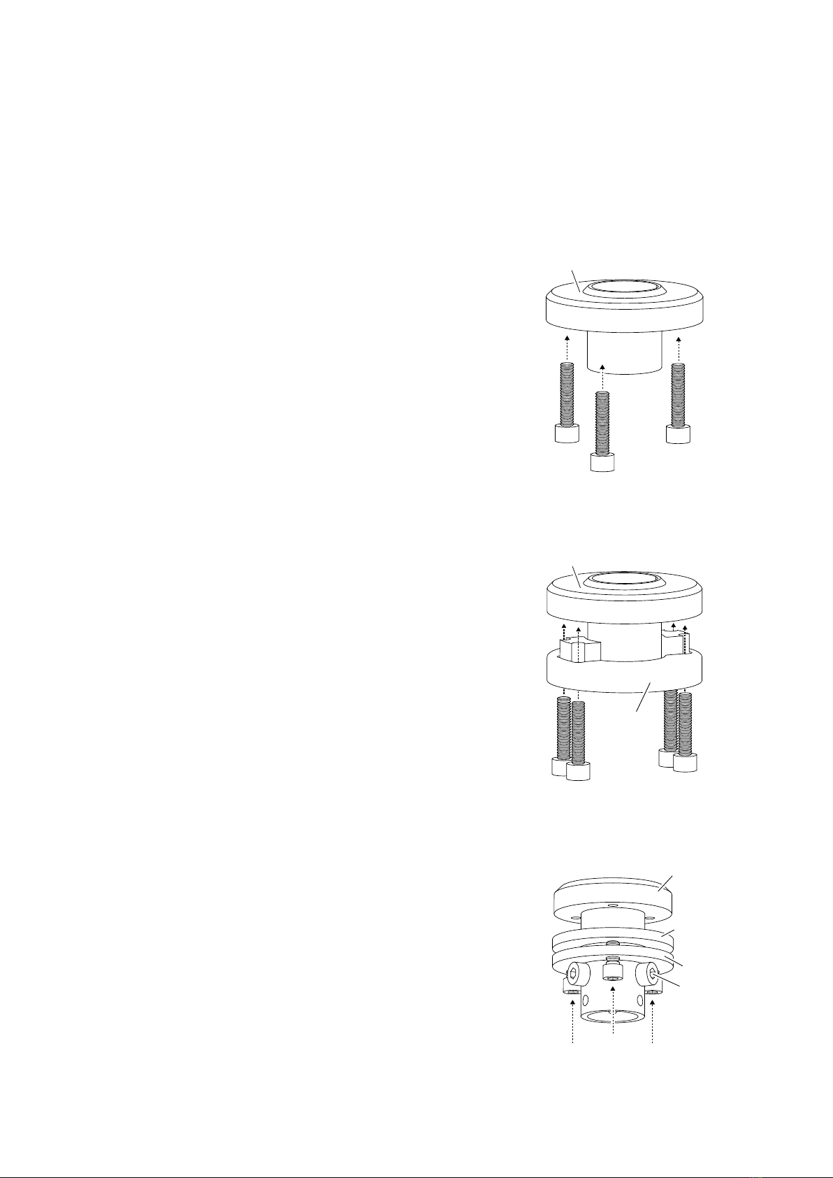
The positions of the pins are shown below:
If you have rotated the Black Knight pin holder
inside the pillar then these pin positions will
also have rotated correspondingly.
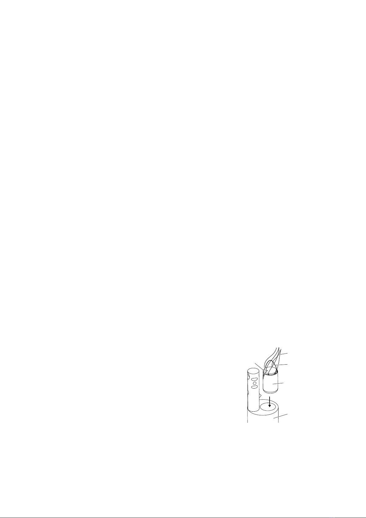
Mount Arm
With the arm held in your left hand about
15mm above the play position to provide slack
in the hoists, insert the hoist toggles into the
small holes on the thrust surface. Take care not
to strain the signal wires. Ensure the hoist
toggles are fully through and snagged. Note that
the left hoist toggle is also attached to the bias
pulley. The right hoist toggle is fixed only to the
right hoist.
If necessary, adjust the hoist spools so that the
arm is suspended by both hoists and level.
Normally there is a clearance of about two
millimetres between the underside of the arm
R- R+
L- L+
red
green
yellow
blue
white
left hoist
toggle
left hoist hole
right hoist
toggle
right hoist hole
10
and the top of the post. This will be accurately
adjusted later during the Calibration process.
If None, Install Cartridge
If you did not install your cartridge before
mounting the arm, place a folded tissue
between the pivot and thrust box to protect
them during cartridge installation.
For a three-bolt mounting, temporarily remove
the finger-lift and use its hole to access the third
bolt with an Allen key or screwdriver.
Large head cartridge bolts or large nuts will not
fit in the headshell. It is possible to file large
bolt-heads and nuts in a drill or by hand.
Contact SUPATRAC if you are unable to
procure compatible bolts.
Attach Counterweight
When setting downforce, always obstruct
movement of the arm by holding it in your left
hand while adjusting the counterweight with
your right. Attach a magnetic counterweight
under the thrust box and squeeze it forwards
for more downforce or backwards for less. Keep
the counterweight centred on the axis of the
arm by pinching the thrust box from both sides
between thumb and fingers. You can centre the
counterweight by feel. Keeping the
counterweight centred in this way makes it less
necessary to adjust lean (azimuth) after
adjusting downforce.
Multiple counterweights are normally supplied
to cater for an extremely wide range of
cartridges weights, compliances and tracking
weights (downforces).
To measure downforce with the supplied
downforce scale, place it on the bare platter
11

with either a penny, a cent or a centime in the
appropriate bed as the balancing weight. The
dimples in the scale represent 1/10 gram
increments in the range 1.2g - 4g. Adjust the
counterweight until the scale balances with
your stylus resting in the dimple corresponding
to your desired downforce.
Level Arm (VTA)
The ‘Vertical tracking angle’ can be set by
raising the pillar. Take care to support the pillar
while loosing the locking screw as there is no
brake. Slide the pillar up or down and tighten
the locking screw gently. The tightness of the
locking screw can affect the sound, so adjust it
to taste. Tighter is not necessarily better.
It may be necessary to re-adjust VTA after
optimising the hoists.
Adjust Hoists
Ensure that the turntable is level before
adjusting the hoist lengths. With the arm in the
playing position adjust both hoist spools so that
the arm is suspended with no lean to the left or
right and the pivot makes contact with the
thrust box exactly on the straight line between
the flex points where the hoists meet the thrust
box. See the section on Calibration for more
information about configuring the hoists.
Set Pivot-Stylus Length
Remove the Supatractor from the platter
spindle and place it under the arm so that the
pivot and protractor points touch. Use the
curved lines to move cartridge to desired pivot-
stylus length.
12
Align Cartridge
Replace the protractor on the platter spindle
and use the null point grids to align the
cartridge.
Install Pivot Magnet
Attach one of the supplied cylindrical magnets
to the flat end of the pivot bolt in order to
augment pivot contact. A 3mm diameter
neodymium magnet is normally adequate.
Set Bias
Initially the anti-skate force can be set by
holding the bias rotor in the vertical position
and gently pulling the loose end of the bias
pulley until it slips and becomes taut. Then
gently cue the arm as far as the record label so
that the pulley slips back to a length which
allows the playing of a full side. For optimising
bias, see the chapter on Calibration.
Adjust Rest Position
In the rest position the thrust box rests against
three M6 screws in the bias rig. Two of these
have embedded magnets which capture the
thrust box, whereas the uppermost screw relies
on the arm’s downforce for contact, and sets the
rest level of the arm. They can be advanced or
withdrawn with an Allen key to achieve a stable
arm-rest position. Ideally both rest magnets will
make contact with the thrust box when the arm
is resting.
13

Add Inertia (Optional)
A nine-inch Blackbird has an effective mass of
around 10g. If you intend to use a mid or low-
compliance cartridge you may wish to add
mass. The external mass adaptor can help to
establish the ideal arm mass for your cartridge.
See the chapter on Calibration for more
information on using the mass adaptor and
calculating an equivalent position for the
permanent internal mass.
mass adaptor
ballast block
14
CALIBRATION
Follow the check-list below routinely to
establish and maintain optimum performance,
especially with a newly-installed arm.
(1) Level Turntable
(2) Set Downforce
(3) Level Arm (VTA)
(4) Set Pivot Contact
(5) Clear Signal Wires
(6) Attach Pivot Magnet
(7) Set Pivot Height
(8) Set Azimuth
(9) Set Bias
(10) Adjust Inertia
A quick guide to calibration is at
www.supatrac.com/calibration
As with all tone arms, inaccurate configuration
can produce poor results, whereas precise
calibration will enable you to get the best from
your records.
Level Turntable
It is important to level the turntable so that the
arm hangs reliably against the bearing.
Set Downforce
Place the downforce scale on the bare platter
with either a penny, a cent or a centime in the
appropriate bed. The dimples in the downforce
scale represent 1/10 gram increments in the
range 1.2g - 4g.
To adjust downforce, hold the arm in your left
hand and squeeze the counterweight forwards
for more downforce or backwards for less.
Adjust the counterweight position until the
15

scale balances with your stylus resting in the
dimple corresponding to the desired downforce.
Keep the counterweights centred on the axis of
the arm by pinching thrust box and
counterweight from both sides so that it is not
necessary to adjust lean (azimuth) after
adjusting downforce.
Level Arm (VTA)
The ‘Vertical tracking angle’ can be set by
raising the pillar. Take care to support the pillar
while loosing the locking screw as there is no
brake. Slide the pillar up or down and tighten
the locking screw gently. The tightness of the
locking screw can affect the sound, so adjust it
to taste. Tighter is not necessarily better.
It may be necessary to re-adjust VTA after
optimising the hoists.
Set Pivot Contact
It is crucial to the correct function of the SUPA
bearing that contact is maintained between the
pivot point and thrust box during playback. To
ensure this, remove the pivot bolt magnet, put
the arm in the play position with a stylus guard
on and gently tap the back of the thrust box.
Any gap between the pivot point and thrust box
should be discernible by sound, feel and seeing
thrust box movement. Even when there is firm
contact, if you look precisely across the thrust
surface, you may see a slight gap between the
hoists and the thrust surface if the hoists are
hanging backwards by a small angle.
Correct these misconfigurations by loosing the
hoist pipe locking screw and moving the hoist
pipe so that its eye is directly above the pivot
16
17
point, and the hoists hang in a vertical plane
while the pivot only just makes contact.
If the hoist pipe position needs adjusting, please
take care not to pinch the hoists with any tool
used for pushing the hoist pipe backwards or
forwards. It is safer to apply pressure to the top
edges of the hoist pipe, not the bottom edges.
Do not overtighten the hoist pipe locking screw
as the thread in the post is short and ductile.
Clear Signal Wires
Ensure that the wires below the thrust box are
not tangled or obstructing arm movement.
Attach Pivot Magnet
Do not forget to return the pivot bolt magnet to
the blunt end of the pivot bolt after adjusting.
Set Pivot Height
A 10 x 60mm slip of paper with straight edges
can be used to set correct pivot height.
Raise the headshell high and insert the paper
between the hoists and the thrust box so that
hoist pipe
hoist pipe eye
hoist pipe
lock screw
pivot bolt
pivot lock nut
pivot
post
pillar
pivot
magnet
pivot bolt straight edge
paper
hoists
thrust box

18
the paper’s straight edge sits on the flex points
where the hoists meet the thrust surface. Pivot
contact should occur just below the paper’s
edge. Adjust the upper and lower spools to level
the arm and raise it to the correct height.
A period of incremental adjustments to pivot
height can establish optimal performance.
Set Azimuth
Lean, commonly called ‘azimuth’, is the extent
to which the cartridge leans towards the centre
of the record or away from it. Zero lean is
important for accurate playback and stylus/
record longevity. Assess lean by looking at the
cartridge from a position precisely on its central
axis while it is playing.
Lean is adjusted by shortening and lengthening
the two hoists in equal and opposite measure so
that the pivot contact remains on the line
between the suspension points. After twisting
the upper and lower spools by equal and
opposite amounts, resettle the bearing by
pushing the arm backwards and gently letting it
settle again. Always check that the pivot contact
lies on this line after lean adjustments by
resettling the bearing and applying the paper
test again.
Set Bias
The anti-skate (‘bias’) mechanism is designed to
balance the forces on each side of the stylus
even though the record pulls the arm at an
angle. The chief benefit of well-calibrated bias is
stylus and record longevity.
Precise instantaneous bias is dependent on
signal strength, record speed, stylus profile and
other factors, so aim for a level of bias which
19
roughly neutralises the net sideways playback
forces on the stylus.
Recommended ways of judging bias are:
-looking at the cantilever exactly head-on
while music is playing and at the moment
when the stylus is lowered into the groove
-observing whether the arm moves
centripetally or centrifugally when the stylus
is lowered onto the flat surfaces between the
grooves
-listening for balance across speakers with
passages which are difficult to track or with a
test/set-up record
-looking for long-term unloaded deflection of
the cantilever to the right (inadequte applied
anti-skate) or to the left (excess applied anti-
skate)
To calibrate bias, first make sure that the signal
wires are free and not constraining arm
movement in any way. The anti-skating force is
supplied by the bias rotor, which pulls the bias
pulley, a nylon filament attached to the left
hoist toggle.
The force can be adjusted by screwing the bias
weight further into the bias rotor or further out.
Different lengths of M6 screw are supplied for
compatibility with the widest range of
rest magnet
bias rotor
spool
grip
hoist spool
pivot lock nut
pivot
pivot magnet
bias pulley

cartridges and downforces. The further the grub
screw is from the rotor’s axle, the more bias will
be applied. Do not tighten as far as the axle.
The difference between the bias at the start and
end of a record can be increased by shortening
the bias pulley or decreased by lengthening it.
To shorten the pulley, pull at the loose end when
the arm is at rest until it slips. To lengthen the
pulley gently cue the arm beyond the end of
side. After adjusting pulley length be sure to
adjust the bias weight screw again. Repeat until
the bias at the beginning and end of the record
are roughly appropriate.
Always lengthen the pulley enough to ensure
that the bias rotor does not reach the vertical
position before the final groove. Always shorten
it enough so that the bias rotor begins to rise
before the arm is cued to the intro groove.
The difference between start and end bias can
be adjusted further by unthreading the bias
pulley from the rotor and re-threading it in a
different hole. The hole nearest the rotor axle
will provide greater difference in applied bias
from start to end, whereas the hole furthest
from the rotor axle will provide the least
difference in bias as the arm progresses across
the record. Re-threading the pulley in the rotor
holes is easier with a needle-threader or a
strand of copper wire bent into a pointed hoop.
A figure-of-eight pattern through three of the
bias rotor’s holes, as illustrated, is normally
bias rotor
bias pulley
20
enough to grip the bias thread while also
allowing it to slip when forced. Add a loop if it
slips too easily.
It is also possible to adjust bias by rotating the
pillar in the base if you have difficulty reaching
correct bias by the above methods.
Finally, if the arm has a strong intrinsic bias
this can be corrected by unhitching the right
hoist toggle, feeding it around the left hoist, and
returning it into the toggle hole.
By these four means applied bias can be
adjusted so that lateral forces are appropriate
across the full width of the playing bands.
Set Arm Inertia (Optional)
When adjusting arm mass, always restrict
movement of the arm by holding it firmly in
your left hand. Arm inertia can be adjusted to
suit your cartridge suspension, either by
calculation or by trial and error. High
compliance cartridges work better with low
inertia, whereas low compliance cartridges
work better with higher inertia.
The external mass adaptor can be pushed up
from under the arm and rotated counter-
clockwise so the hooks straddle it, and then
pushed down to grip it.
The magnetic ballast block can be placed on the
mass adaptor platform to increase mass.
mass adaptor
ballast block
21

Any change in the position of the mass adaptor
requires resetting the downforce. The further
the weights are from the pivot, the higher will
be the arm’s inertia.
The internal permanent mass can be used
instead of the external mass adaptor or in
addition to it. Installation is more complicated
than the external mass adaptor, but it is
invisible inside the arm tube.
WARNING: use protective gloves during
installation of the permanent mass as the tether
and arm can cut your fingers.
WARNING: the carbon-fibre arm tube is fragile
and may crack if excessive force is applied to it
from inside or outside.
If you get stuck installing or removing the
permanent internal mass, please contact
SUPATRAC for advice rather than applying too
much force. Replacement parts are available
from SUPATRAC.
To install the permanent internal mass:
-calculate or guess desired mass position (see
section ‘Calculating Mass Position’ below)
-attach cartridge guard
-dismount arm
-remove cartridge and finger-lift
-squeeze sponge and insert into right arm tube
-use a rod to push it far in
sponge
tether
tether end
free end
mass
22
-insert the free end of the internal mass
-retain a part of the tether
-push the mass to the correct depth
-maintain mass position with rod and pull
tether until mass is firmly wedged
-push surplus tether in to hide it
-re-mount arm
With long arms, heavy cartridges and added
mass it may be necessary to place an additional
counterweight inside the thrust box.
Remove the permanent mass as follows:
-attach cartridge guard
-dismount arm
-remove cartridge and finger-lift
-retrieve tether with a wire hook
-pull mass gently until it dislodges
Calculating Mass Position
To calculate the correct position for the internal
permanent mass using the established external
mass adaptor position:
-measure distance (d) from pivot to centre of
external mass adaptor
-measure internal mass length (L)
-weigh external mass adaptor (m)
-weigh internal mass (M)
-recall arm's effective length (E)
-equivalent distance (D) from arm tip to
internal mass will be:
D = E – ( L / 2 ) – √( m ×d ×d / M )
This does not account for variation to inertia
after counterweight adjustment, but should be
close enough for most purposes.
23

MAINTENANCE
Calibrate Often
Cartridges last better on an arm which is well
set up. Go through the Calibration check list
regularly to ensure optimum performance,
cartridge longevity and for peace of mind.
Thrust Box Bolts
After long periods check that the bolts which
attach the arm to the thrust box are tight. Do
not overtighten as this could split the tubes.
Pivot point
A severely blunted pivot point might
compromise performance. However, it is easy to
replace the pivot bolt with a newly-sharpened
one. A sharpened mild steel M4 bolt suffices.
HSS-tipped pivot bolts are available from
SUPATRAC. Stainless steel is not
recommended.
Hoists
The hoists are made from an extremely hard-
wearing moisture-proof braid. It is not known
how long they will last before needing
replacement. No visible signs of deterioration
have been detected in the first few years of use.
However, in case wear becomes discernible, look
for fraying of the hoists at flexion points like the
hoist pipe eye, which could indicate that they
are ready for replacement.
hoist pipe
hoist pipe eye
hoist pipe
lock screw
pivot bolt
pivot lock nut
pivot
post
pillar
pivot
magnet
24
When replacing hoists, terminate the ends with
simple knots once they are through the hoist
pipe eye, and use the bend of a slip knot around
the hoist toggles.
The slip knot can be loosened in the future and
will disappear if the stop knot is pulled once the
toggle is removed. The stop knot will be small
enough to thread through the hoist pipe eye.
A boom hitch must be tied around the notched
head-end of the spools. A well-tightened boom
hitch should stop the hoist slipping around the
spool and ensure that your tone arm remains
perfectly configured for a long time.
slip knot
hoist spool
stop knot
hoist spool
bunch and tighten
boom hitch
25

DISASSEMBLY
To disassemble, reverse the installation:
-protect your stylus with a guard
-hold the arm in your left hand and raise it by
half an inch to slacken the hoists and unsnag
the hoist toggles, taking care not to tug the
signal wires
-gently lever the peg pot up out of the pillar
using the loop or insert a small Allen key into
the hole for the loop in the peg pot
-the arm is now detached and can be stored
-unplug the amplifier cable from the pillar
-hold the pillar in your left hand and loosen
the pillar locking bolt to remove it
-unbolt and remove the base.
peg pot
loop
wires
pillar
notch
26
SOLVING PROBLEMS
Inconsistent Lean
When the arm is new, or when adjustments are
made, lean may vary slightly between the start
and end of a record. This will normally pass as
the hoists settle in.
If this persists, it may result from under-
extension of the hoist pipe eye relative to the
pivot point. To extend the hoist pipe, loosen the
hoist pipe locking screw and push the hoist pipe
further out so that its eye is directly above the
pivot point. Do not over-extend the hoist pipe
lest contact at the pivot be lost. After extending
the hoist pipe, you can test that contact is still
maintained at the pivot by tapping the back of
the thrust box towards the pivot. There should
be no play or movement.
Excess Bias
Sometimes it can be difficult to set appropriate
bias. The first step in solving excess bias is to
make sure that the arm’s yaw equilibrium is on
or near the playing surface. Balance the arm
with the counterweight so that it floats above
the record surface or rises slowly. Disable the
bias rotor in the upright position with a match
or piece of paper. Observe the default track
position of the arm. If it is not on or near the
playing band, unhitch the right hoist toggle and
feed it around the left hoist in one direction or
the other, and reinsert the hoist toggle, before
pushing the arm backwards and gently allowing
the bearing to resettle. Repeat feeding the right
hoist around the left in one direction or the
other until the arm’s yaw equilibrium is in or
near the playing band. Once this is achieved,
use the three other methods described in the
27

installation and tuning chapters to reach
appropriate bias across the record.
Excess bias may also arise from the eye of the
hoist pipe being too near the post as compared
to the pivot, in which case extend the hoist pipe
as described above.
Contact SUPATRAC if you have any other
problems with the arm.
FURTHER
INFORMATION
SUPATRAC tone arms are designed and made
by hand in Chelsea, London, England.
For further information, please visit
www.supatrac.com or email info@supatrac.com
© SUPATRAC 2023
28

SUPATRAC Blackbird
SET-UP CHECK LIST
1. Level Turntable
2. Set Downforce
3. Level Arm (VTA)
4. Set Pivot Contact
5. Clear Wires
6. Attach Magnet
7. Set Pivot Height
8. Set Azimuth
9. Set Bias
1. Level Turntable
-accurately level turntable
2. Set Downforce
-place balance on bare platter
-lower stylus onto dimples to find
balance weight
-hold the arm in your left hand
while adjusting the
counterweight with your right
-squeeze counterweight towards
pivot to increase downforce and
away to decrease it
-centre counterweight on arm axis
by pinching thrust box and
counterweight from sides
3. Level Arm
-put arm in play position
-view arm from side to see level
-hold pillar/post carefully to stop
it dropping hard when loosing
pillar lock bolt
-raise or lower pillar as required
-don’t overtighten pillar lock bolt
4. Set Pivot Contact
-remove magnet from pivot bolt
-place arm in play position on
stationary record
-gently tap back of thrust box to
check for pivot contact
-look across thrust surface to
check hoists are flush with it
-adjust hoist pipe extension if
necessary by loosing hoist pipe
locking bolt, taking care not to
pinch hoists by pushing top edges
of hoist pipe
5. Clear wires
-check that the arm wires can
move freely and are not tangled
or snagged
-tease them clear of any contact
using an allen key
-make sure they apply no force or
torque on the arm
6. Attach Magnet
-apply magnet to pivot bolt head
-select magnet size to taste
-3mm diameter magnet is
normally adequate
7. Set Pivot Height
-lift headshell high
-insert a 10 x 60mm straight-
edged piece of paper between
hoists and thrust surface
-push paper down onto points
where hoists meet thrust box
-put arm in play position
-adjust hoists so that pivot is at or
just below paper edge
8. Set Azimuth
-observe cartridge and reflection
while playing at middle of side
-turn hoist spools by equal and
opposite amounts so that
cartridge does not lean towards
or away from the spindle
-resettle bearing after hoist length
adjustments by pushing arm back
and letting it settle against the
pivot again
9. Set Bias
-shorten bias pulley by pulling
loose end until it slips
-gently cue arm to the edge of the
label to extend pulley
-aim for slow motion towards
centre on intro and outro flats
-lengthen pulley to make intro and
outro bias more equal
-screw bias rotor bolt in or out for
less or more anti-skate
-if cantilever develops a default
offset, oppose it to compensate
More info: www.supatrac.com
Table of contents