INSTALLATION
SENSOR EXTENSION
RELAY CONTACTS
OPERATION
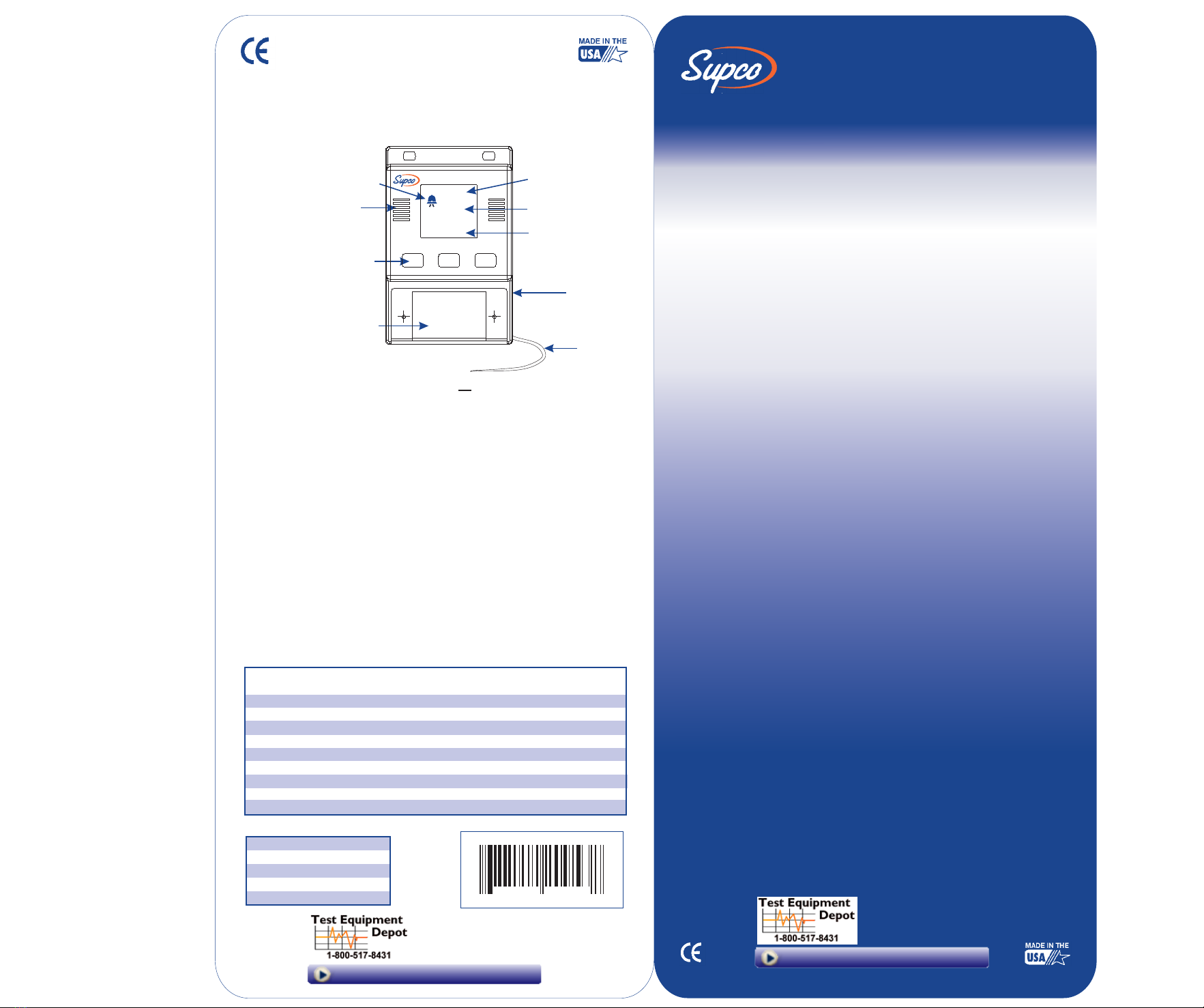
The TA22 may be mounted to any flat surface, in any position, using the two holes provided
at the top of the case or with the supplied adhesive pads. Avoid mounting in areas of
excessive humidity or temperatures outside the operating range of the TA22.
The TA22 sensor probe is designed to measure air temperature and may be mounted in any
Convenient location in the area to be monitored. The sensor probe may be extended up to
200 feet with any 24AWG stranded wire.
The TA22 may be connected to a remote alarm using the relay contacts provided under the
Switch Cover. Connections are provided for Normally Open or Normally Closed Dry Contacts.
Dry Contacts mean that no electrical power is supplied to the contacts and power for a
remote alarm or other device must be supplied externally. When an alarm occurs the N.O.
relay contacts will close and remain closed as long as the alarm condition exists. The relay
contacts will open if the user hits the Silence Alarm button.
Plug the TA22 into a 120VAC (220V available) outlet and verify that the display shows the
current temperature and the Alarm set point. If the display is not on, the TA22 is not receiving
power and is not operating. For continued protection, this requires immediate attention.
Set the temperature alarm threshold to the temperature the TA22 must respond to, using the
Up and Down buttons. Typical values will be between 35 to 45 degrees for a refrigerator and
0 to 15 degrees for a freezer. The setting of this adjustment will depend on the type of
protection the TA22 is being used for and it is up to the judgment of the user to select an
appropriate alarm temperature.
The TA22 is set at the factory to alarm on a RISE above the set temperature, after a one-hour
delay. The OVER/UNDER Switch is in the OVER position and the DELAY/NO DELAY switch is
set to the DELAY position.
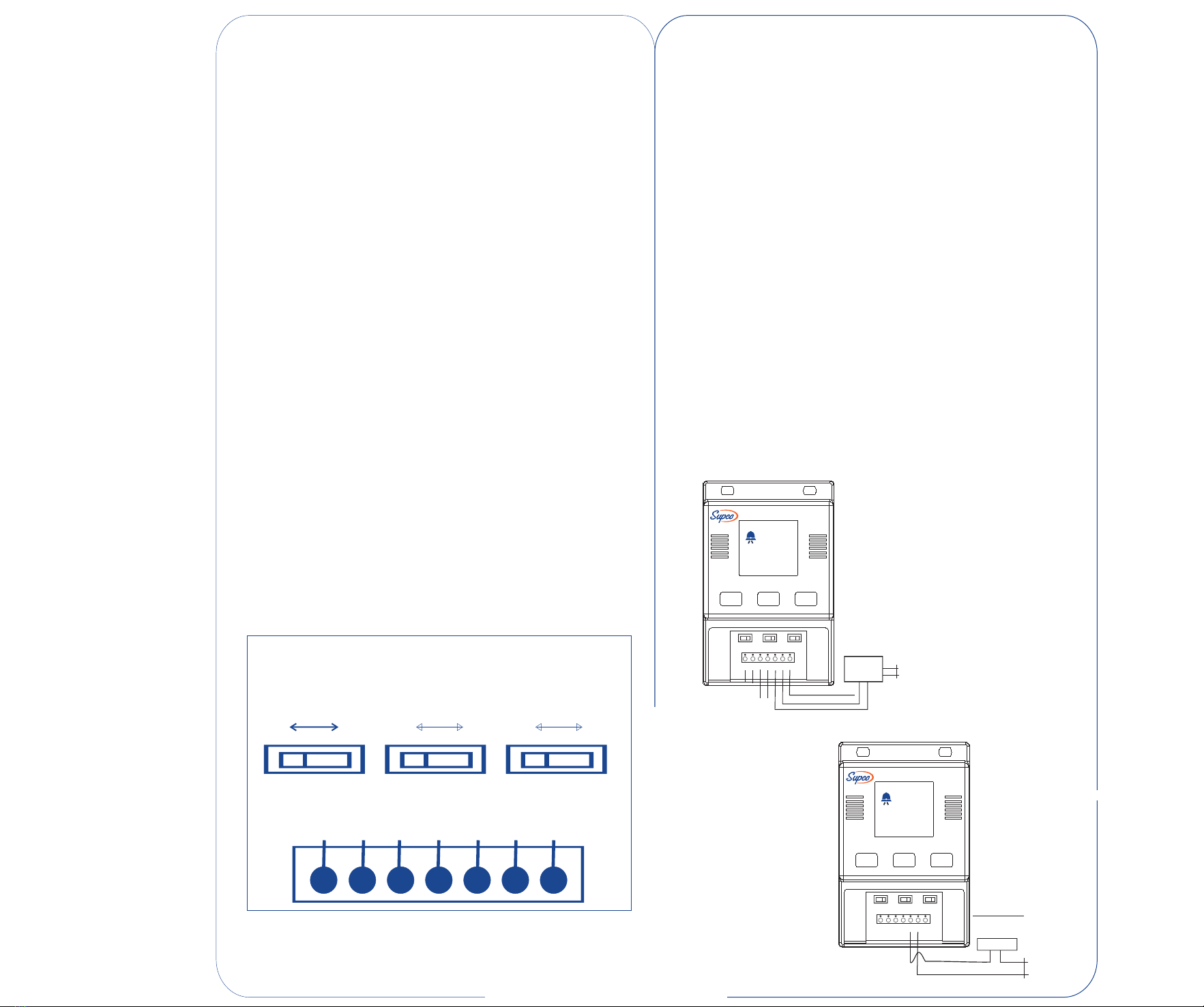
To change the operation of the TA22, remove the switch cover. SW1 controls the DELAY/NO
DELAY operation. Setting this switch to NO DELAY will activate the audible alarm and the
N.O. relay switch as soon as the probe temperature reaches the set point temperature.
SW2 controls the OVER/UNDER operation of the unit. Setting this switch to OVER will cause
the alarm to be activated when the sensor temperature rises ABOVE the temperature setpoint.
Setting this switch to UNDER will cause the alarm to activate when the sensor temperature
falls BELOW the temperature set point. SW3 controls the temperature units displayed
(°F or °C).
Probe
Probe
12 VDC
12 VDC
Common
Normally Open
Normally Closed
SW2
TYPICAL CONNECTIONS ARE SHOWN IN THE DRAWING
Locate SW1, the switch on the left hand side. Note the lettering above this switch (DELAY
– NO DELAY). Setting this switch to DELAY will cause the TA22 to blink the ALARM and
BELL ICONS when the Sensor temperature passes the threshold set by the Front Panel
Adjustment. When approximately one hour has passed and the Sensor temperature has
remained past the threshold set by the Front Panel Adjustment, the TA22 will sound the
audible alarm and close the N.O. relay contacts. Should the temperature return to its
normal value before this period has elapsed, the one-hour delay will be reset. Setting this
switch to NO DELAY will cause the TA22 to sound an immediate alarm and display the
ALARM and BELL ICONS (Solid) when the temperature passes the threshold set by the
Front Panel Adjustment. Should the temperature return to its normal value, the TA22 will
automatically reset.
Locate the terminal strip below the switches. This is where sensor probe, power supply
and remote alarm are connected to the TA22. The TA22 comes from the factory with the
power supply and sensor probe attached. Note the 3 unused terminals on the right. These
are the relay contacts for use with external devices, such as remote alarms or automatic
dialers. Since each installation has different requirements, it is suggested you consult the
instructions supplied with any remote device prior to making any connections to the TA22.
Note the 5 Amp 120VAC rating of the relay contacts. PERMANENT DAMAGE will result if
these limits are exceeded.
TA22 WARRANTY
LIMITED TO ONE YEAR FROM DATE OF PURCHASE
Sealed Unit Parts Co., Inc. warrants its products to be free from defects in materials and
workmanship under normal use and service. Sealed Unit Parts Co., Inc. will repair or
replace without charge any such products it finds to be so defective on its return to Sealed
Unit Parts Co., Inc. The foregoing is in lieu of all other expressed or implied warranties,
including those of merchantability or fitness for a particular purpose. The foregoing is also
the purchaser’s sole remedy and is in lieu of all other guarantees, obligations or liabilities or
any consequential or incidental damages attributable to negligence or strict liability.
TA22
UP DOWN SILENCE
ALARM
SET
OVER
43
40
°F
°F
SW1
SW2
SW3
1 2 34567
Common
Normally Open
Power
Supply
Normally Closed
AUTOMATIC
PHONE
DIALER
TA22
UP DOWN SILENCE
ALARM
SET
OVER
43
40
°F
°F
Sw1
SW2
Sw3
1 2 34567
Common
Light Bulb, Buzzer,
Relay, ETC.
IF USING Light
AS LOAD,
LIMIT BULB TO
100 W MAX.
Normally Open
Power
Supply
LOAD
Probe Power
N/O
Com.
N/C
DELAY
NO DELAY
OVER
UNDER
°F °C
SW1 SW2 SW3
Terminal Board
12 VDC
12 VDC
Probe
Probe