elsner elektronik Salva KNX TH User manual

Salva KNX TH, Salva KNX basic
Smoke alarm
Technical specifications and installation instructions
Item numbers 70405 (Salva KNX basic), 70406 (Salva KNX TH)
Elsner Elektronik GmbH Control and Automation Engineering
Sohlengrund 16
Germany Fax +49 (0) 70 33 / 30 945-20 www.elsner-elektronik.de
EN
Technical Service: +49 (0) 70 33 / 30 945-250

2 Description
Smoke alarm Salva KNX • Version: 30.01.2017 • Technical Changes and Errors excepted.
This document describes the functions for ALL device models.
Please check the information at the beginning of the chapter and in the
text which describes the functions available for the respective individual
models.
1. Description
Salva KNX TH and Salva KNX basic are smoke detector sensors for the KNX build-
ing bus system. Their compact housing accommodates the sensors, evaluation circuits
and bus-coupling electronics.
The smoke alarm features an automatic evaluation sensor system for early and accu-
rate fire alarms. Alarms are output as a local acoustic signal and a bus telegram. Salva
KNX basic signals smoke alarm, Salva KNX-TH signals smoke and/or heat alarm.
AND logic gates and OR logic gates allow for a link between data and statuses. Multi-
functional modules change input data as required by means of calculations, querying
a condition, or converting the data point type.
The Salva KNX TH model additionally features integrated sensors for temperature
and air humidity. The measured values can be used for the control of limit-dependent
switching outputs. The devices have PI controls for heating/cooling (depending on
temperature) and for ventilation (depending on humidity).
Functions:
•Smoke alarm sensors with optical detection based on the scattered light
principle, certified according to EN 14604:2005/AC:2008 and 1172-CPR-150013.
Local acoustic alarm signal output (warning sound at least 85 dB) and transfer
to KNX bus. Local alarm acknowledgement
• Signalling of smoke alarm
• Smoke chamber pollution measurement and pollution display according to UL
directive
• Power supply via battery (9 V). Lack of battery capacity is signalled optically
and acoustically for 30 days and transmitted to the bus
• High operative safety due to elaborate automatic self-testing of the entire
electronics and separate energy measurement
• Faults signalled locally and via the bus
• High deceptive alarm immunity due to powerful measuring chamber and
consideration of temperature fluctuations (though no temperature smoke
alarm)
•8 AND and 8 OR logic gates each with 4 inputs. All switching events as well
as 16 logic inputs (in the form of communications objects) can be used as
inputs for the logic gates. The output from each gate can be configured
optionally as 1-bit or 2 x 8-bit
•8 multi-function modules (computers) for changing the input data by
calculations, by querying a condition or by converting the data point type
•4 actuating variable comparators to output minimum, maximum or
average values. 5 inputs each for values received via communication objects

3 Description
Smoke alarm Salva KNX • Version: 30.01.2017 • Technical Changes and Errors excepted.
Additional functions for Salva KNX TH:
• Signalling of heat alarms
•Temperature sensor and air humidity sensor with mixed value calculation,
dewpoint calculation, comfort field query (DIN 1946)
•Threshold values for measured and calculated values, adjustable via
parameters or communication objects
•PI control for heating/cooling (depending on temperature)
•PI controller for ventilation (depending on air humidity)
Configuration is made using the KNX software ETS. The product file can be down-
loaded from the Elsner Elektronik website on www.elsner-elektronik.de in the “Ser-
vice” menu.
1.0.1. Deliverables
• Sensor (housing with skirting)
•9Vbattery
• 2 screws and dowels for assembly (always use fastening material that is
suitable for the material underneath)
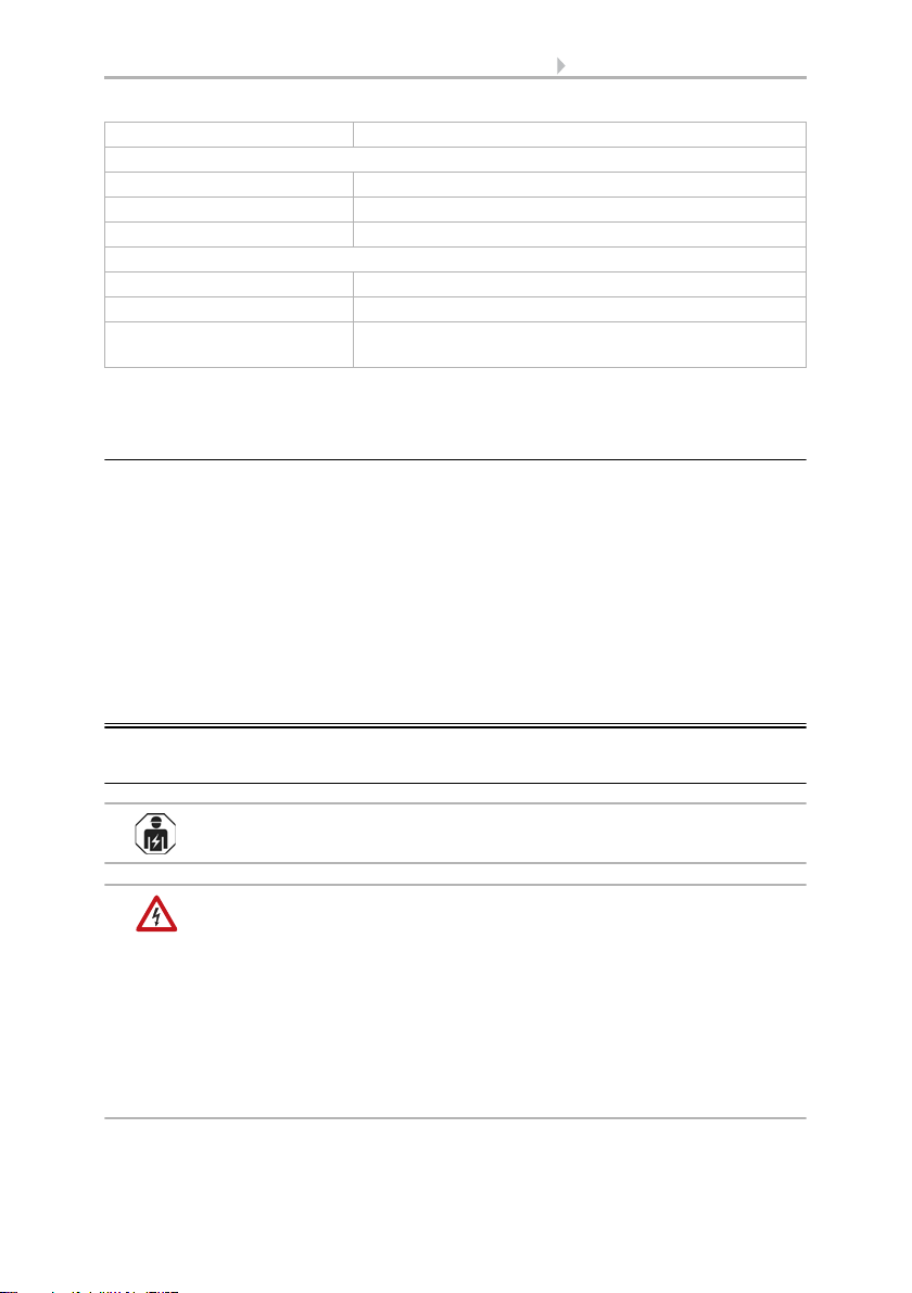
1.1. Technical specifications
Housing ABS, glass
Colour White / Translucent
Assembly Surface mount
Protection category IP 30
Dimensions Ø approx. 113 mm, height approx. 58 mm
Weight approx. 280 g
Ambient temperature Operation -10…+60°C, storage -10°C … +60°C
Surrounding air humidity max. 90% RH, avoid condensation
Operating voltage 9 V (battery)
Auxiliary supply KNX bus voltage
Data output KNX +/- bus connector terminal
BCU type Integrated microcontroller
PEI type 0
Communication objects Salva KNX TH: 311
Salva KNX basic: 192
Smoke alarm:
Detection principle Tyndall effect (optical)
Alarm display optically (LED red) and acoustically
(signal tone >85 dB(A) / 3 m)
Complies with EN 14604:2005
Max. monitoring area 60 m² to 6 m height
Air velocity max. 20 m/s
Response sensitivity 0.15 dB/m typical
4 Installation and commissioning
Smoke alarm Salva KNX • Version: 30.01.2017 • Technical Changes and Errors excepted.
* Please note the information on Accuracy of temperature/humidity measurement, page 4
1.1.1. Accuracy of temperature/humidity measurement
Only for Salva KNX TH model.
Measured value deviations for temperature and humidity due to sources of interfer-
ence (see chapter Installation location) must be corrected in the ETS in order to ensure
the specified accuracy of the sensor (offset).
During temperature measurement, the self-heating of the device is taken into con-
sideration by the electronics. The software compensates the self-heating by reducing
the measured temperature. During the 2 hour warm-up phase, the displayed interior
temperature measured value increasingly approaches the actual room temperature.
2. Installation and commissioning
2.1. Installation notes
Installation, testing, operational start-up and troubleshooting should
only be performed by an electrician.
CAUTION!
Live voltage!
There are unprotected live components inside the device.
• National legal regulations are to be followed.
• Ensure that all lines to be assembled are free of voltage and take
precautions against accidental switching on.
• Do not use the device if it is damaged.
• Take the device or system out of service and secure it against
unintentional use, if it can be assumed, that risk-free operation is no
longer guaranteed.
Shelf life for the alarm max. 2 years
Temperature sensor (Salva KNX TH):
Measurement range -10…+60°C
Resolution 0.1°C
Accuracy* ±0,5°C at -10...+60°C
Humidity sensor (Salva KNX TH):
Measurement range 0% RH … 90% RH
Resolution 0.1% RH
Accuracy ± 7,5% RH at 0% …10% RH
± 4,5% RH at 10% … 90% RH

5 Installation and commissioning
Smoke alarm Salva KNX • Version: 30.01.2017 • Technical Changes and Errors excepted.
The device is only to be used for its intended purpose. Any improper modification or
failure to follow the operating instructions voids any and all warranty and guarantee
claims.
After unpacking the device, check it immediately for possible mechanical damage. If it
has been damaged in transport, inform the supplier immediately.
The device may only be used as a fixed-site installation; that means only when assem-
bled and after conclusion of all installation and operational start-up tasks and only in
the surroundings designated for it.
Elsner Elektronik is not liable for any changes in norms and standards which may occur
after publication of these operating instructions.
2.2. Installation location
2.2.1. Equipping the building with smoke alarms
The minimum protection is the installation of smoke alarms in the bedrooms and halls
and/or corridors to ensure that you are woken up during the night in case of a smoke
alarm. If the building has several floors, at least one smoke alarm should be installed
in the hall on every floor. Please refer to DIN 14676 for further installation guidelines.
2.2.2. Positioning and distances
Install the smoke alarm on the room ceiling. If the smoke alarm is installed in the mid-
dle of the room, it has its best detection characteristics.
WARNING!
Mains voltage for in-wall concealed cables!
• If the device is attached by means of screws, first ensure
that there is no power line installed under the assembly point!
Fig. 1
Minimum equipment
Ideal equipment
Equipment with limitations
Maintain a minimum distance of 50 cm to:
• walls
•lamps
• live wires
≥50 cm

6 Installation and commissioning
Smoke alarm Salva KNX • Version: 30.01.2017 • Technical Changes and Errors excepted.
Small rooms: If the minimum distance to the wall cannot be maintained, install the
alarm on the wall. Keep a distance of at least 0.50 m and maximum 1 m to the ceiling.
Rooms with a gallery: Attach an additional alarm underneath the gallery if said gal-
lery is longer and wider than 2 m and has more than 16 m².
Segmented ceilings: If there are separate areas in the ceiling with a depth of more
than 0.20 m and an area of more than 32 m² (e.g. due to beams separating the areas),
install an alarm in each area (on the ceiling or on the beams).
The device is only approved for interior spaces. Do not install in rooms
with temperatures of less than -10°C or more than +50°C! Avoid
condensation.
Do not install in rooms in which a high degree of water vapour is
produced under normal circumstances (e.g. kitchen, bathroom, toilet)!
Do not install near places of fire or open fireplaces!
Do not install near ventilation shafts (e.g. of air conditioning or
circulating air systems)!
Attach the first alarm at a maximum distance
of 7.50 m to the end of the room in long struc-
tures. Distribute at least 3 alarms on 15 m of
corridor. Attach alarms in the middle of cor-
ners and crossroads in the corridor.
Halls and corridors:
≤15 m ≤7,5 m
≤7,5 m
x
0,50 m < x < 1 m
x
< 1 m
0,50 m < x < 1 m
≥1 m
A + B: For pointed and flat gables with a ceiling area of less than 1 m width: Attach
alarms at a minimum distance of 0.50 m and a maximum distance of 1 m to the top.
C: For flat gables with a ceiling area of more than 1 m width: Attach to the middle of
the ceiling like in other rooms.
ABC
Gables:
7 Installation and commissioning
Smoke alarm Salva KNX • Version: 30.01.2017 • Technical Changes and Errors excepted.
Do not paint the smoke alarms!
Avoid the following sources of interference in order to limit distortion of measuring re-
sults for temperature, humidity and pressure:
• Direct sunlight
• Draughts from windows and doors
• Warming or cooling of the building structure on which the sensor is mounted,
e.g. due to sunlight, heating or cold water pipes
• Connection lines, which lead from warmer or colder areas to the sensor
Temperature variations from such sources of interference must be corrected in the ETS
in order to ensure the specified accuracy of the sensor (temperature offset).
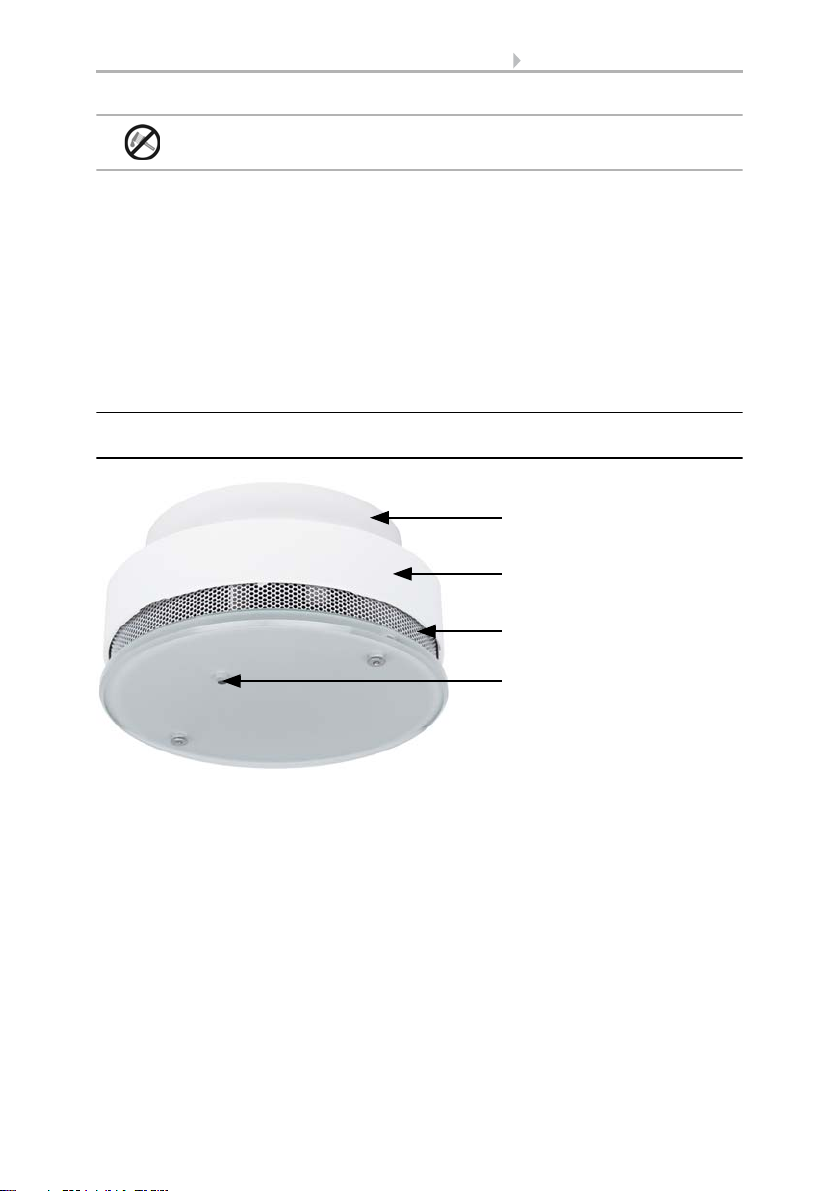
2.3. Device design
2.3.1. Exterior view
2
Fig. 2
1Skirting
2 Housing with electronics and battery
3 Openings for air circulation
4 Light transmission bar: Red LED for Operating and alarm signals, page 14 and
Push-button for Function test, page 12
3
4
1
8 Installation and commissioning
Smoke alarm Salva KNX • Version: 30.01.2017 • Technical Changes and Errors excepted.
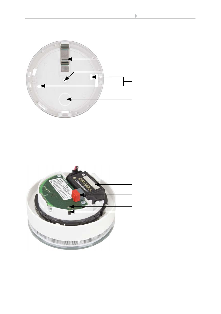
2.3.2. Skirting
2.3.3. Interior view of the housing
2
Fig. 3
1 Battery assembly lock (the housing cannot be closed without a battery)
2 Fastening opening with 1 screw
3 Openings for fastenings with 2 screws (distance 67 mm)
4 Opening for bus cable
3
4
1
2
Fig. 4
1Battery
2 KNX terminal
3 LED programming
4 Programming key (recessed) for bus addressing,
see Addressing the equipment, page 11
3
4
1
9 Installation and commissioning
Smoke alarm Salva KNX • Version: 30.01.2017 • Technical Changes and Errors excepted.
2.4. Installing the device
2.4.1. Instructions for assembly and initial start-up
Never expose the device to water (e.g. rain) or dust (e.g. drilling dust). This can damage
the electronics and the sensor system. A relative air humidity of 93% may not be ex-
ceeded. Avoid condensation.
After the bus voltage has been applied, the device will enter an initialisation phase last-
ing a few seconds. During this phase no information can be received or sent via the
bus.
2.4.2. Assembly preparation and skirting assembly
Determine the installation point on the room ceiling. Please observe the instructions in
chapter Installation location, page 5 for this.
BEWARE!
Injury hazard in case of improper fastening!
The device may fall and injure people if it is not fastened properly.
• Observe, the carrying capacity of the wall/ceiling material when
selecting the place of installation.
• Use fixing materials that are suitable for the material underneath.
If you are using the screws and dowels provided, use a 6mm drill to drill holes with a
distance of 67 mm (if you are using two screws for installation). Use the skirting of the
smoke alarm as a stencil. Insert the dowels into the drilling holes.
As an alternative, the skirting of the alarm may be attached to the ceiling with double-
sided adhesive pad (VdS approved). Carefully check the ceiling surface carefully for
lasting carrying and adhesive capacity before using adhesive pads. If necessary, do a
test glueing application. Optimum adhesive power can only be obtained on a clean sur-
face.
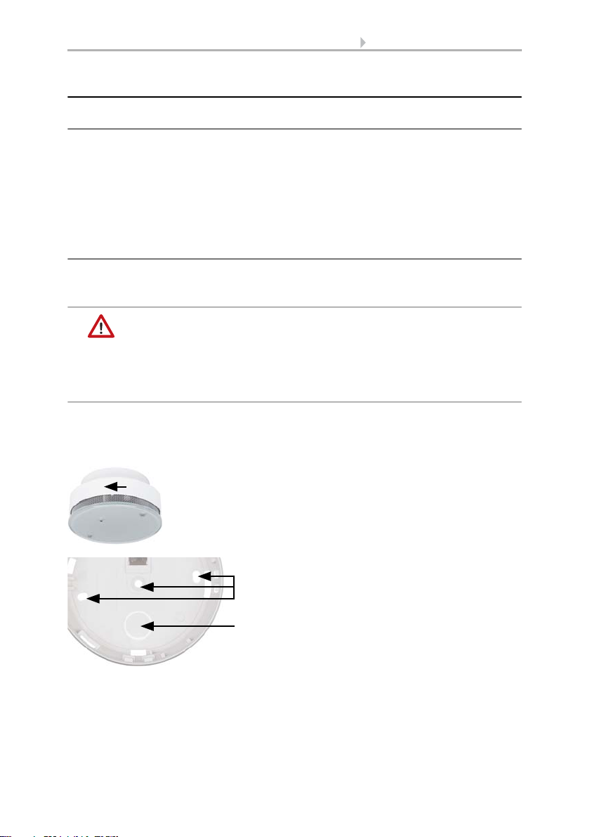
Fig. 5
The housing is removed from the skirting by
turning it anti-clockwise.
Fig. 6
Remove the cover on the opening for the sup-
ply line (1) from the skirting and thread the ca-
ble through it.
Screw the smoke alarm skirting onto the ceil-
ing (2, openings for screws).
2
1

10 Installation and commissioning
Smoke alarm Salva KNX • Version: 30.01.2017 • Technical Changes and Errors excepted.
Remove the protective foil form one side of the adhesive pad and attach the pad in the
middle of the alarm skirting. Then remove the protective foil on the other side and at-
tach the skirting by firmly pressing it to the ceiling.
2.4.3. Connection
The supply line of the smoke alarm occurs via a 9 V battery. In addition, the KNX mod-
ule receives the bus voltage via the KNX terminal.
WARNING!
Danger of explosion in case of improper handling of the battery!
Property damage by battery leakage.
• Do not recharge batteries.
• Do not short-circuit batteries.
• Do not force batteries open or damage them
• Do not bring batteries in contact with fire, water or high
temperatures.
ATTENTION!
Do not use rechargeable batteries or mains units for voltage
supply!
• In case of mains voltage, the device would be out of order
if the mains is out and could not signal any fire.
• The lower rechargeable battery voltage would trigger
a low battery capacity alarm.
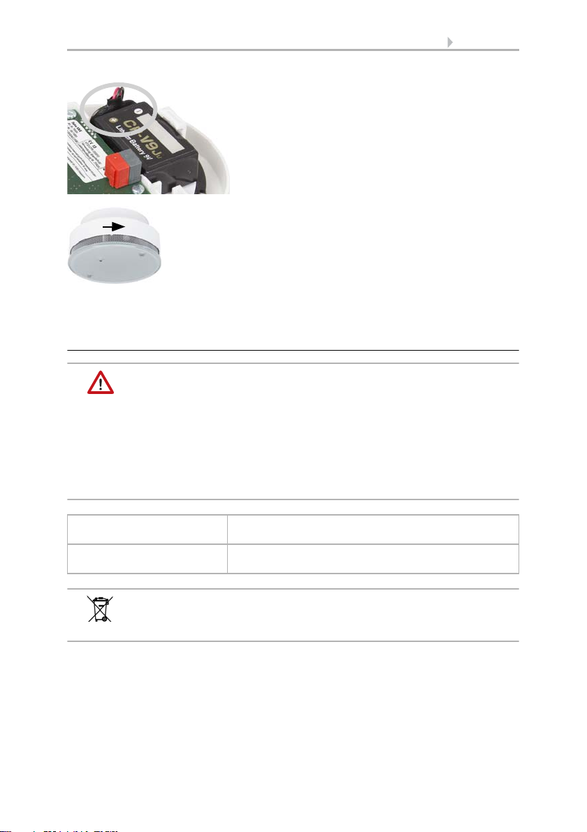
Fig. 7
1. Connect the battery (check for correct polar-
ity!) and insert it into the battery compartment.
2. Connect the device to the KNX bus via the
pluggable terminal (+|-).
1
2
-
+
-
+
KNX

11 Addressing the equipment
Smoke alarm Salva KNX • Version: 30.01.2017 • Technical Changes and Errors excepted.
2.4.4. Completing the installation
Check if the LED is flashing and conduct a function test.
> Function test, page 12
3. Addressing the equipment
The equipment is delivered with the bus address 15.15.250. You can program a differ-
ent address in the ETS by overwriting the address 15.15.250 or by teaching the device
via the programming button.
The programming button is on the inside of the housing. The housing is removed from
the skirting by turning it anti-clockwise, and fixed in place by turning clockwise.
4. Maintenance
In some German federal states, the owner of houses and flats are responsible for the
installation and functioning of smoke alarms according to LBO (State construction
laws) (see www.rauchmelder-lebensretter.de). Maintenance has to be conducted at
least annually and, according to DIN 14676 includes a visual inspection, a function test
and, if required, a battery change. A function test also has to be conducted after any
longer absence, at ,after 1 year at the latest.
The used battery and the device must be disposed of correctly so that
valuable resources may be recycled. Neither the battery nor the device
may be disposed of together with domestic or company
waste.
Fig. 8
Place the housing onto the skirting and fasten
it by turning it clockwise.
Fig. 9
Use a thin object to reach the button, e.g. a
wire.

12 Maintenance
Smoke alarm Salva KNX • Version: 30.01.2017 • Technical Changes and Errors excepted.
4.1. Function test
BEWARE!
Danger of hearing damage!
During the function test (pressing on the light transmission bar),
a loud, shrill tone is sounded (at least 85 dB).
• Keep a minimum distance of 50 cm between smoke alarm and ear.
1. Conducting a visual inspection:
Check:
• Is the device found at the expected position?
• Are the smoke entry openings clean? - Remove dust if necessary. The device
must not be painted over.
• Is the device free from mechanical damage? - Replace the device if it is
damaged.
2. Conducting a function test:
If the function test is successful, a signal tone sounds. The smoke alarm works proper-
ly. If there is no signal tone, the device is not functioning. In this case, replace the bat-
tery and conduct the function test again. If there is still no signal tone, the device is de-
fect and must be replaced.
Smoke alarms must be replaced with new devices after a maximum
period of 10 years according to DIN 14604.
4.2. Replace the battery
The device is supplied with 9 V voltage from a battery. Lack of battery capacity is sig-
nalled optically and acoustically for 30 days and transmitted to the bus.
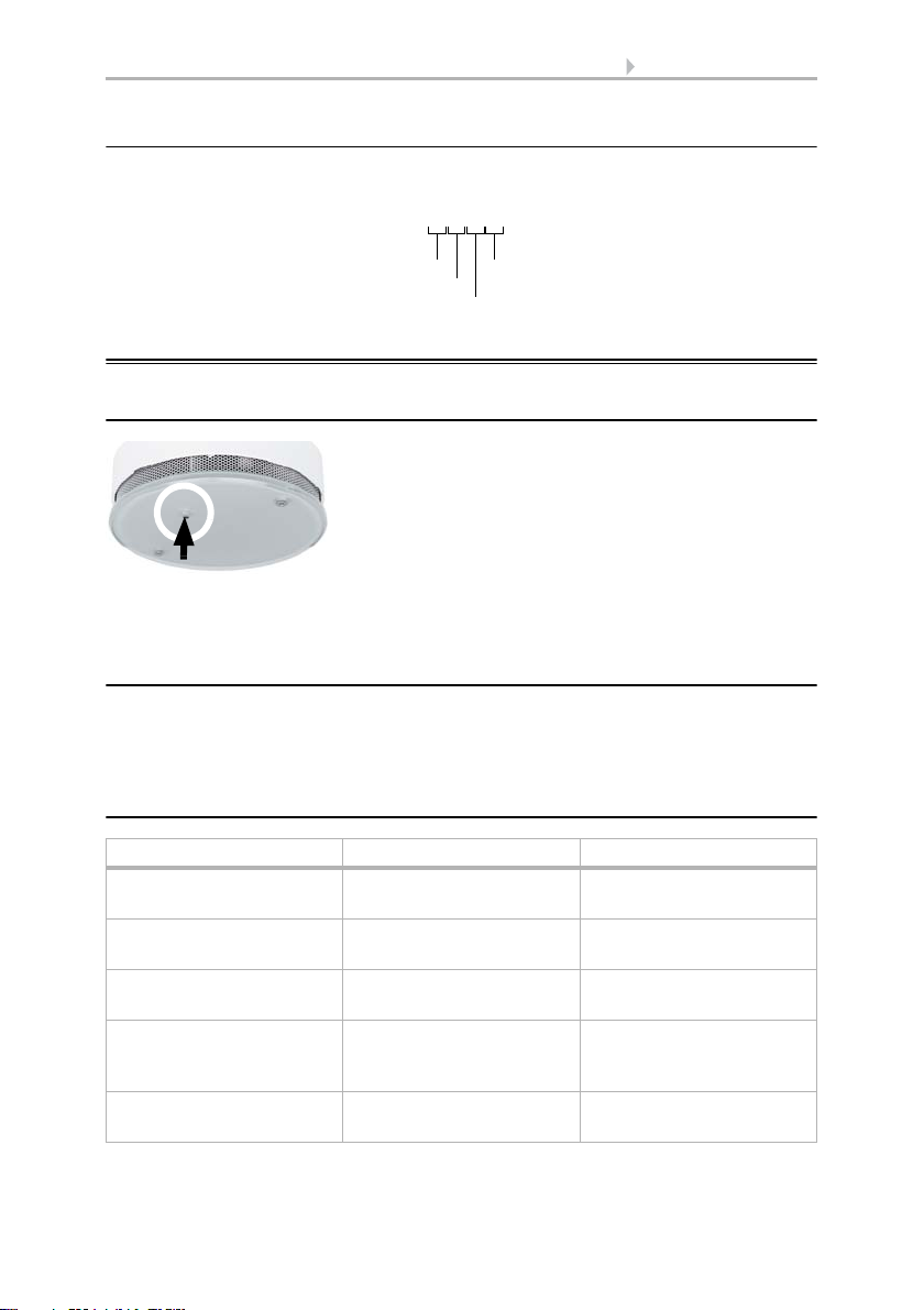
Fig. 10
Press the light transmission bar for at least 1
second.
Fig. 11
Separate the smoke alarm from the skirting
by turning it anti-clockwise.
13 Maintenance
Smoke alarm Salva KNX • Version: 30.01.2017 • Technical Changes and Errors excepted.
Check if the LED is flashing and conduct a function test.
> Function test, page 12
4.2.1. Types of batteries
WARNING!
Danger of explosion in case of improper handling of the battery!
• Only replace with a lithium battery type DFK CP-V9Ju.
• Do not use rechargeable batteries or mains units for voltage supply
to ensure a sufficiently high voltage and supply even in case
of a mains outage.
• Do not recharge batteries and do not short-circuit them.
• Do not force batteries open or damage them and do not
bring them into contact with fire, water or high temperatures.
The used battery and the device must be disposed of properly so that
valuable resources may be recycled. Neither the battery nor the device
may be disposed of together with domestic or company waste.
Approved battery type FDK CP-V9Ju
Only use lithium batteries
Average service life approx. 10 years (typical),
under normal conditions as per EN 14604
Fig. 12
Connect the new battery to the smoke alarm
(check for correct polarity!) and insert it into
the battery compartment.
Fig. 13
Place the housing with the new battery onto
the skirting and fasten it by turning it clock-
wise.
14 Device alarm functions
Smoke alarm Salva KNX • Version: 30.01.2017 • Technical Changes and Errors excepted.
4.2.2. Serial number
The serial number on the type plate inside the device contains the production data and
device number:
5. Device alarm functions
5.1. Alarm mute (acknowledgement)
In this case, only the LED continues to flash every 10 seconds. After about 10 minutes,
the devices switches back to normal operating mode.
5.2. Alarm memory
An alarm is saved in the device for 24 hours. During this time, the LED briefly flashes
3 times every 43 seconds. The alarm memory can be reset by pressing the light trans-
mission bar (red LED) once.
5.3. Operating and alarm signals
Function / meaning Signal tone Red LED
Normal operating mode
(automatic self-test)
No sound Flashes every 40 seconds
Alarm status Loud interval tone in
0.5 second rhythm
Flashing twice per second
Fault / dirt Short signal tone 3 times
every 40 seconds
LED off
Battery exchange display 1x Short signal tone
every 40 seconds
Flashes every 40 seconds
together with the signal
tone
Alarm mute (acknowledge-
ment)
No sound Flashes every 10 seconds
Ser.no. 25111601
Day of production
Month
Yea r
Device number
Fig. 14
The alarm can be muted by pressing the
flashing light transmission bar.

15 Device alarm functions
Smoke alarm Salva KNX • Version: 30.01.2017 • Technical Changes and Errors excepted.
Alarm memory active
(i.e. there was an alarm
state during the previous
24 hours)
No sound Flashes 3 times every 43
seconds
Function test Loud interval tone Flashing twice per second
while the light transmis-
sion bar
is pressed
Function / meaning Signal tone Red LED
Other manuals for Salva KNX TH
1
This manual suits for next models
3
Table of contents
Other elsner elektronik Smoke Alarm manuals


Popular Smoke Alarm manuals by other brands

System Sensor
System Sensor BEAM1224 Installation and maintenance instructions

System Sensor
System Sensor DH100ACDCLP Installation and maintenance instructions

General Monitors
General Monitors L3100H manual

Hochiki
Hochiki SLR-24 installation instructions

Crow
Crow FW2-SMK installation instructions

Cabletech
Cabletech SMOKE & CO URZ0413 owner's manual


 Series installation manual")


