Super Circuits AVSI-12 Safety guide

AVSI-12 Interview Room System
Setup and User Guide
PLEASE READ THIS MANUAL BEFORE USING YOUR SYSTEM, and always follow the
instructions for safety and proper use. Save this manual for future reference.
AVSI-12_SM
200302

ii www.Observint.com
CAUTION
Operate this system only in environments where the temperature and humidity is within the recommended range. Operation in
temperatures or at humidity levels outside the recommended range may cause electric shock and shorten the life of the product.
Refer to the specications for each system component for more information.
LEGAL NOTICE
Observint products are designed to meet safety and performance standards with the use of specic Observint
authorized accessories. Observint disclaims liability associated with the use of unapproved accessories.
The recording, transmission, or broadcast of any person’s voice without their consent or a court order is strictly
prohibited by law.
Observint makes no representations concerning the legality of certain product applications such as the making,
transmission, or recording of video and/or audio signals of others without their knowledge and/or consent. We
encourage you to check and comply with all applicable local, state, and federal laws and regulations before
engaging in any form of surveillance or any transmission of radio frequencies.
Microsoft, Windows, and Internet Explorer are either registered trademarks or trademarks of Microsoft Corporation in
the United States and/or other countries. Android is a trademark of Google Inc. Use of this trademark is subject to
Google Permissions. Apple, iPhone,iPod touch, and iPad are registered trademarks of Apple Inc.
Other trademarks and trade names may be used in this document to refer to either the entities claiming the marks
and names or their products. Observint, Inc. disclaims any proprietary interest in trademarks and trade names
other than its own.
No part of this document may be reproduced or distributed in any form or by any means without the express written
permission of Observint, Inc.
© 2017, 2018, 2019. 2020 Observint Technologies. All rights reserved.
15505 Long Vista Drive, Suite 250, Austin, TX 78728
For Sales and Support, please contact your provider.

iiiAVSI-12 Interview Room System Setup and User Guide
TABLE OF CONTENTS
Table of Contents
SECTION 1 Systems Overview...................................................................1
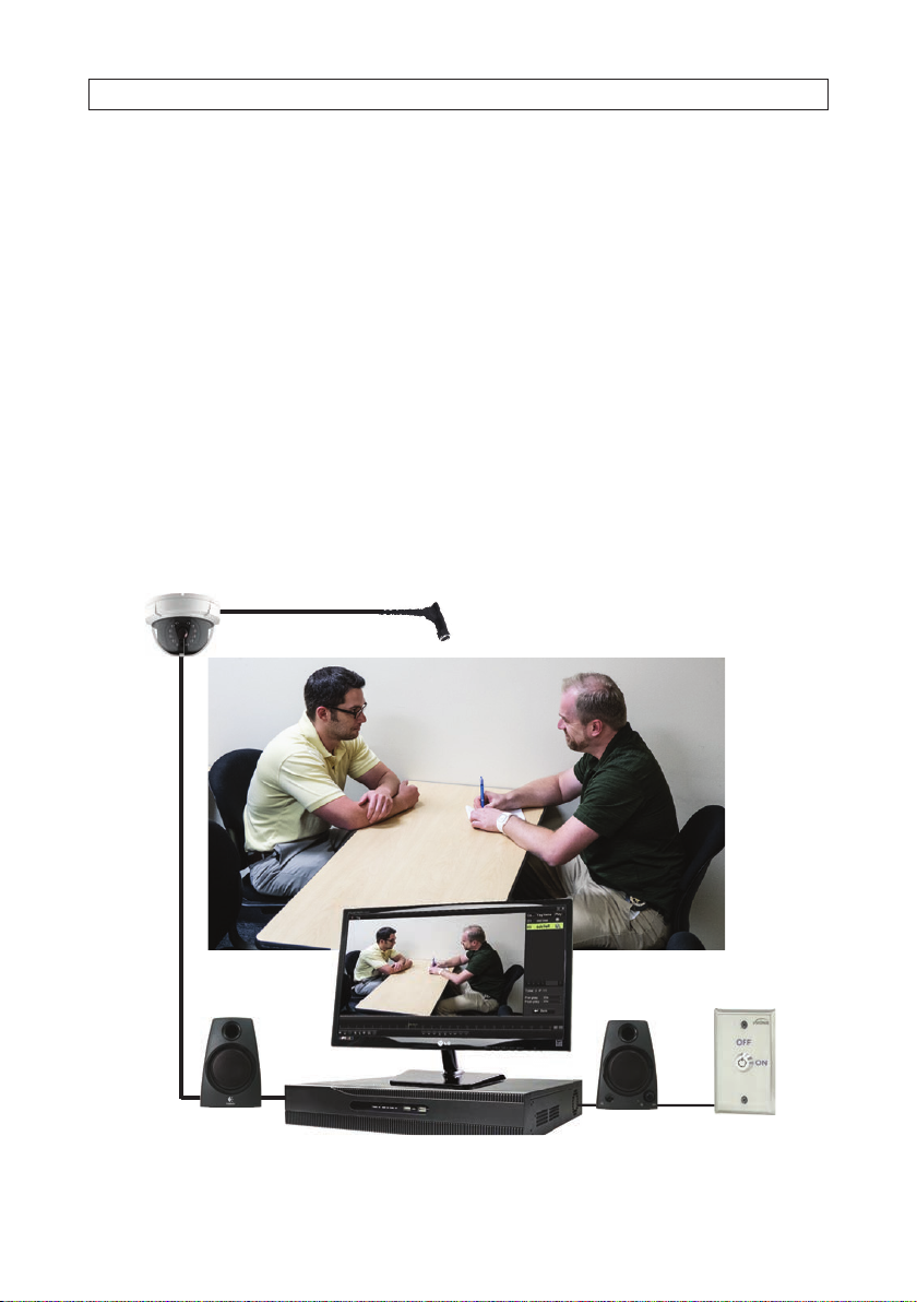
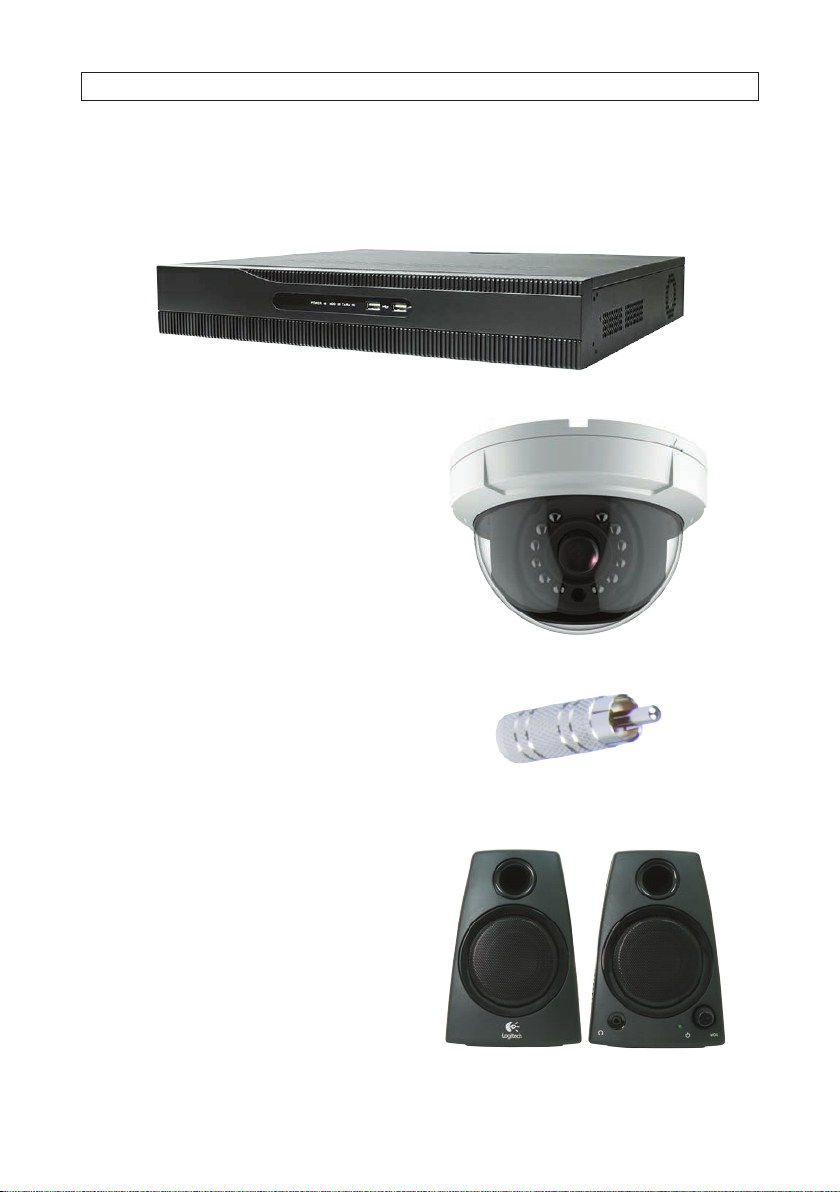
1.1 System components*.................................................................2
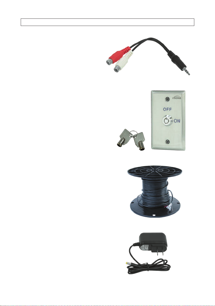
1.2 Optional equipment..................................................................5
SECTION 2 Getting Started .....................................................................6
2.1 Unpacking the equipment.............................................................6
2.2 What you need ......................................................................6
SECTION 3 System Setup.......................................................................7
3.1 Install the recorder hardware ..........................................................7
3.2 Mount and wire the AVSI switch........................................................8
3.3 Connect the CAB-ASK cable to the recorder Alarm In terminals..............................9
3.4 Connect the speakers to the recorder...................................................10
3.5 Install the ALI-TS1012R camera and PA6IL microphone ...................................11
3.6 Powering on the system for the rst time ..............................................13
3.7 System activation . . . . . . . . . . . . . . . . . . . . . . . . . . . . . . . . . . . . . . . . . . . . . . . . . . . . . . . . . . . . . . . . . . .14
3.8 Using the setupWizard ..............................................................18
3.9 Opening the Menu system. . . . . . . . . . . . . . . . . . . . . . . . . . . . . . . . . . . . . . . . . . . . . . . . . . . . . . . . . . . .23
3.9.1 Camera OSD setup ..............................................................23
3.9.2 Camera Image Settings..........................................................25
3.9.3 Camera Video Parameters........................................................26
3.10 Setup alarm triggered recording. . . . . . . . . . . . . . . . . . . . . . . . . . . . . . . . . . . . . . . . . . . . . . . . . . . . . . .28
3.10.1 Conguring Record schedule .....................................................28
3.10.2 Congure Alarm IN 1 and recording trigger .........................................32
SECTION 4 Test/Use the Interview Room System .................................................35
4.1 Test System ........................................................................35
4.2 Playback recorded video .............................................................36
4.3 Export recorded video ...............................................................39
4.4 Tagging and locking recorded video clips ...............................................44
4.4.1 Tagging video les..............................................................44
4.4.2 Locking a video le .............................................................46
4.4.3 Search for and Playback aTagged le .............................................46
4.4.4 Search for and play locked les ...................................................48
4.5 Manual recording ...................................................................50
4.6 Export system conguration ..........................................................50
4.7 Import system conguration. . . . . . . . . . . . . . . . . . . . . . . . . . . . . . . . . . . . . . . . . . . . . . . . . . . . . . . . . .52
APPENDIX A Playback Screen Controls............................................................54
A.1 Playback screen basic controls ........................................................54

iv www.Observint.com
TABLE OF CONTENTS
A.2 Normal Playback....................................................................55
APPENDIX B Advanced Recorder Features.........................................................57
B.1 User Management ..................................................................57
B.2 Remote Access......................................................................58
B.3 System Maintenance ................................................................58

1AVSI-12 Interview Room Switch Systems Setup Guide
SECTION 1
Systems Overview
The AVSI-12 Interview Room system is a premium quality scalable video and audio digital recording system ideally suited for indoor
installation in rooms where interviews or interrogations occur. The digital recording system allows you to search and playback live
video and audio, and export recordings locally or download them remotely. Additionally, you can expand the system to monitor and
record up to 4 interview rooms simultaneously.
This document include complete instructions for setting up your AVSI-12 Interview Room System. These instructions will congure
the system to record video and audio on Channel 1 when the AVSI switch is ON. While recording, the video stream from Channel
01 will expand to full screen. Also included here are instructions for playing back video and downloading it. After conguring
and testing the system, ALIBI Support highly recommended that the system conguration le be saved to an external device. The
Conguration le can be use to quickly restore the system to its saved conguration, if necessary.
The recorder can be networked on a LAN and congured for remote access, providing live view, playback, download and manual
recording capabilities.
PA6IL microphone
AVSI-SW
switch
ALI-TS1012R camera
24LGLED
monitor
ALI-QVR4108H recorder
AVSI-SPEAKER
speakers
AVSI-12 System Components
SECTION 1: SYSTEM OVERVIEW

2www.Observint.com
SECTION 1: SYSTEM OVERVIEW
1.1 System components*
The interview room system components include:
Quantity SKU Description
124LGLED LG™24” 1080p Full-HD Widescreen Commercial Grade LED Monitor
1ALI-QVR4108H1TB AKI-QVR4100 series 8-channel HD-TVI Hybrid+ security DVR
1ALI-TS1012R HD-TVI 2MP indoor dome camera
1AUDIOADAPTER Mono audio 3.5mm female to RCA male adapter
1AVSI-SPEAKER Powered stereo speaker set
1AVSI-STEREO Adapter cable
1AVSI-SWITCH AVSI system control switch
1CAB-ASK 100 ft 3 conductor
1DC12-2000R 12 Vdc 2A power adapter
1EXT100 100 ft Video/Audio/Power extension cable
1PA6IL
High Fidelity, Low Noise microphone with DC IN/OUT
* This list subject to change.
24LGLED Monitor
This Alibi 24 Inch widescreen security-grade LED Monitor oers high-resolution viewing and is engineered for 24/7 surveillance
environments. The slim 16.7 million color LED display brings your surveillance video to life with vivid, colorful images. The anti-
glare monitor features a 1920 x 1080 (1080p) full-HD display resolution enabling you to view your security video with exceptional
clarity and detail on a high-resolution screen.

3AVSI-12 Interview Room System Setup and User Guide
SECTION 1: SYSTEM OVERVIEW
ALI-QVR4108H1TB Recorder
The ALI-QVR4108H hybrid+ digital video recorder supports 1080p HD-TVI, analog and IP cameras and includes a pre-congured
1TB HDD. It can be contain up to two HDDs, each with a capacity of 8TB for a maximum system capacity of 16TB.
ALI-TS1012R Camera
The ALI-TS1012R HD-TVI 2MP indoor dome camera include
a new generation sensor with high sensitivity and advanced
circuit design technology. It feature low image distortion and
low noise which makes them suitable for surveillance and
image processing systems.
AUDIOADAPTER
Converts 3.5 mm plug go RCA male.
AVSI-SPEAKER Speakers
The AVSI-SPEAKER is a high quality computer compatible
powered stereo speaker set. It connects to the audio out jack on
the back of the ALI-QVR4108H recorder.

4www.Observint.com
SECTION 1: SYSTEM OVERVIEW
AVSI-STEREO adapter cable
RCA audio left and right to 3.5 mm stereo connector adapter
cable.
AVSI-SWITCH system control switch
The AVSI-SWITCH is a simple interview room switch assembly
that can be used to start and stop recording equipment with
the key provided. The switch provides normally open contacts
(N.O.) to two independent pair of leads colored blue and yellow.
The procedure in this document uses the blue leads to activate
recording.
CAB-ASK
The CAB-ASK is a 3-conductor spool of bulk cable for use between
the Alarm In connectors on the recorder backpanel and the AVSI
switch.
DC12-2000R 12 Vdc power adapter
The DC12-1000R is a regulated 12 Vdc 2 amp (2000 mA)
power adapter. This power adapter is used with the YPOWER
splitter to power the camera and the microphone.

5AVSI-12 Interview Room System Setup and User Guide
SECTION 1: SYSTEM OVERVIEW
EXT100 100 ft Video/Audio/Power extension cable
The EXT100 features:
• 100 ft Video, Audio & Power Cable
• HD-TVI, HD-SDI, AHD, HD-CVI, 960H and HD AVS
• RCA Audio, RCA Video Connection
• Includes RCA to BNC adapters for video
• 2.1 x 5.5mm Power Connector (Standard)
PA6IL High Fidelity, Low Noise microphone with
DC IN/OUT
TThe miniature Surface Mount Technology (SMT) design of this
microphone is ideal for the hidden installation you need for covert
audio surveillance. With an output impedance of 600 ohm, this
mini audio monitoring device captures crisp, clear sound with
high-delity and low noise. The monitoring scope reaches up to
164 sq ft, and you can easily connect this device to video recorders
and IP cameras.
1.2 Optional equipment
UPS-1000 Uninterruptible power supply (UPS)
The highly recommended UPS-1000 features 890 /1080
Joules of surge protection, and provides battery backup during
power outages. It includes automatic voltage regulation
for inconsistent utility power, automatically increasing or
decreasing input voltage to a consistent 110 Vac ~ 120 Vac
output. Integrated batteries provide power when the incoming
voltage drops below 90 Vac or increases above 140 Vac.
The UPS is used to distribute power to the recorder, monitor,
AVSI switch, camera and audio base station.

6www.Observint.com
SECTION 2: GETTING STARTED
SECTION 2
Getting Started
2.1 Unpacking the equipment
Remove the equipment from its packaging and place it on a at, clean surface. Inspect each item. If any visible damage is present,
contact your supplier for a replacement. Verify that your order is complete. Within your order you should nd one of each of the
following:
• 24LGLED: LG™23” 1080p Full-HD widescreen commercial grade LED monitor
• ALI-QVR4108H1TB: ALI-QVR4100 series 8-channel HD-TVI Hybrid+ security DVR
• ALI-TS1012R: HD-TVI 2MP indoor dome camera
• AUDIOADAPTER: Mono audio 3.5mm female to RCA male adapter
• AVSI-SPEAKER: Powered stereo speaker set
• AVSI-STEREO: Adapter cable
• AVSI-SWITCH: AVSI system control switch
• CAB-ASK: 100 ft 3 conductor bulk cable spool
• DC12-2000R: 12 Vdc 2A power adapter
• EXT100: 100 ft Video/Audio/Power extension cable
• PA6IL: High Fidelity, Low Noise microphone with DC IN/OUT
NOTE
This system may be shipped in several cartons.
2.2 What you need
• #2 Phillips screw driver
• Thin blade screwdriver
• Wire stripping tool (to strip 22 ga wire)
• Tools for installing the camera and microphone

7AVSI-12 Interview Room Systems Setup Guide
SECTION 3: SYSTEM SETUP
SECTION 3
System Setup
The basic Interview Room System system includes an ALI-QVR4108H HD-TVI digital video recorder, an HD-TVI 1080p high denition
camera, a hi-gain microphone and speakers.
3.1 Install the recorder hardware
Installing the recorder hardware includes the ALI-QVR4108H HD-TVI recorder and the 24LGLED monitor. A uninterruptible power
supply (UPS), not provided, is strongly recommended. When installing this equipment, refer to the ALI-QVR4100H 8/16-Channel
AHD, HD-TVI, Analog and IP Camera Recorder Quick Setup Guide and documentation provided with the monitor and other
system components for more information.
NOTE
Powering the interview room system through a 1000 VA uninterruptible power supply (UPS) is strongly recommended. A UPS is
not provided.
1. Place the ALI-QVR4108H unit in a secure location that is within cable distance to the interview room(s) you are monitoring,
and in a location that has restricted access. Using the cables provide:
—Cable (EXT100) between the recorder and the camera and microphone is 100 feet. (Longer cables are available. The
ALI-TS1012R camera can be extended with a cable length up to 1600 feet.
—Cable (CAB-ASK) between the recorder and the switch is 100 feet.
2. Become familiar with the back panel of the ALI-QVR4108H recorder. The connection points for the devices included in this
interview room system are shown in the images below.
12 VDC Plug for
power adapter
VIDEO IN CH 1
for camera
AUDIO OUT
to speakers
AUDIO IN CH 1 input
from microphone
LAN
Ground
terminal
Power
switch
HDMI/VGA
to monitor
Alarm Terminations
(See image below)
ALARM IN 1 GROUND (G)

8www.Observint.com
SECTION 3: SYSTEM SETUP
3. Connect a ground cable to the ground terminal on the back of the recorder. Follow local electrical codes to ensure the
recorder is properly grounded.
4. Plug the mouse provided into the USB port on either the front or back of the recorder.
5. Position the monitor in an appropriate viewing location and connect it to the recorder using either the VGA or HDMI interface.
A VGA cable is provided with the 24LGLED monitor, but the HDMI interface provides the best performance.
6. If the recorder will be accessible across a local LAN, connect it to a LAN at this time.
NOTE
Do not power on the recorder or monitor at this time. The power switch on the recorder is located on the back panel near the 12V
power adapter input.
3.2 Mount and wire the AVSI switch
The AVSI switch is used to start and stop recording on channel. Find the best location to locate the switch. NOTE: A 100 ft CAB-ASK
cable provided is used to connect the switch to the recorder.
1. Route the CAB-ASK cable between the recorder and the location where the AVSI switch will be mounted.
Switch leads, two pair:
White - Green (N.C.) and
Yellow-Green (N.O.)
Lead
functions
2. Find a convenient location for the switch, and then route the CAB-ASK cable to where the switch will be mounted.
3. If mounting the switch onto an electrical box (not provided), connect an earth ground cable to the ground terminal inside the
box if required by your local electrical codes.
4. Remove about 2” of insulating sheath from the end of the CAB-ASK cable.
5. Strip 1/4” of insulation from both the red and black wires using a 22 gauge wire stripping tool.
6. Connect the red lead of the CAB-ASK cable to the yellow lead from the switch.
Connect the black lead of the CAB-ASK cable to a green lead (COM) from the switch. See below.

9AVSI-12 Interview Room System Setup and User Guide
SECTION 3: SYSTEM SETUP
NOTE
Functions of the wires attached to the switch may change. Always wire the switch so that it functions as a Normally Open (N.O.)
switch.
CAB-ASK cable
to recorder
White and
green leads
(unused)
7. Insulate the ends of the white lead and one green lead from the switch using electrical tape. Be certain that they are not
electrically connected together.
8. Anchor the CAB-ASK cable to electrical box (if used) or to a wall to prevent it from being pulled away from the switch. Leave
a few inches of extra cable between the anchor and the switch for maintenance when needed.
9. Mount the switch plate securely to a wall or electrical box, as determined earlier.
3.3 Connect the CAB-ASK cable to the recorder Alarm In termi-
nals
At the back panel of the recorder, do the following:
1. Remove about 2” of insulating sheath from the end of the CAB-ASK cable.
2. Strip 1/4” of insulation from both the red and black wires using a 22 gauge wire stripping tool.
3. At the alarm terminations, push and hold in the orange button associated with the ALARM IN 1 terminal, insert the CAB-
ASK cable red wire all the way in, and then release the orange button. Tug on the wire to ensure that is securely attached.

10 www.Observint.com
SECTION 3: SYSTEM SETUP
ALARM IN (1)
CAB-ASK cable
To AVSI switch
Back of recorder
Ground (G)
4. Push and hold in the orange button associated with one if the G(ground) terminals, insert the CAB-ASK cable black wire all
the way in, and then release the orange button. Tug on the wire to ensure that is securely attached.
3.4 Connect the speakers to the recorder
The speakers provided with the system connect to the recorder AUDIO OUT connector through the AUDIOADAPTER. The AUDIO OUT
connector is located on the back of the recorder between the VGA connector and the LAN connector.
1. Plug the audio cable from the speakers into the AUDIOADAPTER provided, and then into the AUDIO OUT connector on the
back of the recorder. See below.

11AVSI-12 Interview Room System Setup and User Guide
SECTION 3: SYSTEM SETUP
AUDIOADAPTER Cable to speakers
AUDIO OUT connector
2. Plug the power adapter provided with the speakers into the power port on the back of the speakers.
3.5 Install the ALI-TS1012R camera and PA6IL microphone
When performing the following instructions, refer to the ALI-TS1012R HD-TVI 2MP Indoor Dome Camera Quick Installation
Guide provided with your camera for additional information.
1. Mount the ALI-TS1012R camera in the interview room in accordance with the mounting guidelines provided in the
installation instructions. Ensure that the camera location will provide the best eld of view of both the interviewer(s) and
those being interviewed. Note that the camera module is mounted on an internal gimbal to adjust it’s tilt and direction.
a. After mounting the camera, leave the dome cover o. The camera direction and tilt will be adjusted after the recorder
is powered on.
2. Install the PA6IL microphone to achieve optimal recording of the subject being interviewed and all other room occupants,
be away extraneous noise, such as from HVAC vents, fans and sounds outside the room, and in a location where it cannot be
easily tampered with. Do not install the microphone on the table where occupants can reach it. Both the camera drop cables
and the microphone drop cables must be able to connect to the same EXT100 video-audio-power extension cable.
3. Route the EXT100 video, audio and power extension cable from the recorder to the camera and microphone. Notice that the
power connectors are dierent at the ends of the cable (see photo below). Ensure that the power connector on the recorder
end will mate with the connector on the DC12-2000R (2 amp) power adapter, and the power connector at the camera and
microphone end will connect to the YPOWER adapter.

12 www.Observint.com
SECTION 3: SYSTEM SETUP
Power connector
for recorder end
Power connector
for camera end
4. Connect the EXT100 extension cables to the recorder as follows:
a. Connect the EXT100 cable video (yellow) connector to an RCA to BNC adapter, and then connect the adapter to the
VIDEO IN 1 BNC connector. See below.
DC12-2000R (2 amp)
power adapter
EXT100 cable (recorder end)
To camera and microphone
RCA female to BNC adapter VIDEO IN 1 (BNC) AUDIO IN 1 (RCA)
b. Connect the EXT100 cable with the RCA connector (audio, white connector) to the AUDIO IN 1 connector.
c. Connect the EXT100 power cable (red connector) to the DC12-2000R power adapter. NOTE: Do not plug the power
adapter into a power outlet at this time.
5. Connect the EXT100 extension cables to the camera and microphone as follows:

13AVSI-12 Interview Room System Setup and User Guide
SECTION 3: SYSTEM SETUP
a. Connect the EXT100 cable video (yellow) connector to an RCA to BNC adapter, and then connect the adapter to the
camera drop cable with the BNC connector (video). See below.
EXT100 cable
(camera end)
EXT100 power cable
PA6IL power
input
PA6IL audio
output
PA6IL power pass through
EXT100 audio (RCA)
Camera drop cables
Camera video (BNC)
EXT100 video (RCA)
PA6 ILmicrophone
Power
RCA female to BNC adapter
b. Connect the EXT100 power cable (red RCA connector) to the PA6IL red RCA connector.
c. Connect the EXT100 audio cable (white RCA connector) to the PA6IL white RCA connector.
d. Connect the PA6IL black RCA connector to the camera drop cable grey power connector.
3.6 Powering on the system for the rst time
Powering on the system for the rst time includes steps to perform the initial recorder conguration and verify system functionality.
When performing this procedure, refer to the following documents, provided with the system hardware, for more information:
ALI-QVR4100H Series 8/16-Channel AHD, HD-TVI, Analog and IP Camera Recorder Quick Setup Guide
Embedded Video Recorder Firmware V4.20.00 (or later) User Manual provided online by your equipment vendor.
ALI-TS1012R HD-TVI 2MP Indoor Dome Camera Quick Installation Guide
During the initial startup of the recorder, the conguration Wizard is executed. This Wizard provides windows for performing the
initial conguration of your system, including changing the administrator password (highly recommended), setting the network
parameters, adding IP cameras to the system and other options. Use the instructions below to customize your system for your
location.
NOTE
Important note about setting your admin password
After setting the administrator password of the system, an option is available to save a GUID le. This le can be used to reset
the Admin password of the system if you forget your password. Save the GUID le on a USB ash media drive and stored in a
secure location.

14 www.Observint.com
SECTION 3: SYSTEM SETUP
14
When the recorder is rst powered on, it is in an “Inactive” state, which means that it does not have an admin user password for
the recorder, and it is not congured to record video or log system status messages. The initial conguration screen enables you to
activate the recorder.
After activating the recorder and conguring its security options, a conguration Wizard will open. The Wizard helps you to easily
congure the recorder for its basic settings, including date and time, network conguration, network cameras, HDD initialization,
etc.
NOTE
After completing system setup with the Wizard, the recorder will record on Channel 1 when the AVSI switch is ON,
and record on other all other channels with cameras when motion is detected on that channel.
3.7 System activation
1. Power on the recorder. Normally, an Alibi logo splash screen appears within 2 minutes.
2. Power on the camera.
3. The following screen is used to activate the recorder.

15AVSI-12 Interview Room System Setup and User Guide
SECTION 3: SYSTEM SETUP
15
In the screen above:
a. Click on the Create New Password eld, and then enter a unique password using the pop-up virtual keyboard.
Follow the guidelines in the Note at the bottom of the screen. Always use a password that will produce a “Strong”
rating (green indicator in the status bar).
b. Enter the same New Password in the Conrm New Password eld. Select or deselect the check boxes for:
Reserved E-mail Settings: This feature enables you to reset the admin password of recorder through scanning the
QR code.
Export GUID: This feature enables you to create a GUID le and save it to a ash drive for logging back into the
recorder if you loose your admin password.
Enable Unlock Pattern: This option allows you to login by dragging the mouse across a 3 x 3 matrix to quickly
login to your admin account.
Security Question Conguration: If you loose your password, this option enables you to login by responding
correctly to security questions you setup.
c. Enter a password in the Create Channel Default Password eld. This will become the default password of the
admin user of IP network cameras. Follow the guidelines in the Note below this eld.
4. Click the OK button to continue. If passwords were setup properly in the Activation menu, an Note window will appear
showing the recorder is now “activated.” Leave the Note window open.

16 www.Observint.com
SECTION 3: SYSTEM SETUP
16
5. If you selected options for Reserve E-mail Setting, enter a valid email address in the pop-up window.
a. Click OK. Your email address will be veried.
b. In the Note window, click OK to continue.
6. If you selected the option in the Activation screen to Export GUID, use the instructions in this step to use this feature.
a. Plug a ash drive into an unused USB port on the recorder, and then click the Refresh icon (see below).
Refresh
icon
b. In the GUID Import/Export window, open the Device Name drop down list and then select the device where you
want to save the GUID le. If a list of directories appear, click on the directory you prefer (in the window shown above,
the rst directory was selected). Some options will appear at the bottom of the screen to add a New Folder or Erase
les.
Other manuals for AVSI-12
1
Table of contents
Other Super Circuits Recording Equipment manuals