manuals.online logo
Brands
  1. Home
  2. •
  3. Brands
  4. •
  5. Super Flying Model
  6. •
  7. Aircraft
  8. •
  9. Super Flying Model HAWK GLIDER User manual

Super Flying Model HAWK GLIDER User manual

INSTRUCTION MANUAL
MTH HOBBY PRODUCTS INDUSTRIAL CO., LTD.
www.mth.com.tw
MTH HOBBY 2015
HAWK GLIDER
SPECIFICATIONS
Wing Span: 2000mm
Wing Area: 42 dm²
Length: 1043mm
Total Weight: 950g
Radio: 4 channels
Motor:
ECO 2820C-940KV brushless
Propeller: 12 x 8”
Thrust: 1 KGS and up
Battery: Li-Po 3-cell 2200mAh and up
ESC: 40A
1 2
Made a Z-bend on one end of the rod
using Z bender.
Connect the female plug of the 300mm
extension with the male plug of the
servo. Use transparent tape to circle
the connecting place for preventing
loosening.
Tight a cotton line on the male plug of
the extension. Route the line through
the pre-drilled holes in the rid. Cut off
the cotton line when the extension is
out of the hole.
Take the control horn and M2x15
screw out the hardware. Assemble
just like the illustrator. Please note
that the control horn must
beperpendicular to the control
surface when secure the control
horn.
The whole accessories including in this kit.
Recommended radio and electronic equipment (Not included in kit):
4 Channels radio
Mini servos x 4 pieces
Receiver
300mm extension x 2 pieces
Optional accessories
Recommended radio and electronic equipment (Not included in kit)
Required Tools and Adhesives
#2421
40A brushless
Speed Control
#2820
940KV
brushless motor
Epoxy 5-minute
Small Phillips Screwdriver
Pen
2mm driller Curved scissors
CA glue
Z bender
1.5mm Hex wrench
Hobby Knife
Ruler
Pliers
Y-harness x 1 piece
40A speed control
Li-Po 2100mA 3 cells battery pack
Propeller: 12X8
Paper Tape
Lubricating Oil
Soldering Iron
Solder
Spray epoxy on the wing joiner and
insert into the main wing for
securing the A section and B
sectiontogether. Please note the
B section must be 4 degree above
the horizontal and its wing tip will
be 42mm above the horizontal.
Spray Super glue on the hinges.
Use hinges to connect the main
wing with aileron and secure with
M2x6mm tapping screws. Use
hinges to connect the tail wing with
rudder and elevator. Secure the
hinges in place with M2x5mm
tapping screws.
AB
AB
Super glue
34
Use hobby knife to cut off the balsa
wood on the rear edge on the
horizontal.
Try to fit the horizontal to the fuselage.
Please note that the horizontal must
Using hobby knife, carefully cut the
covering inside the marking lines.
Please do not press hard enough to
cut into the wood as doing so could
weaken the horizontal.
Spread epoxy on the top and bottom
of the horizontal where it comes into
contact with the fuselage. Lay the
horizontal onto a flat work surface and
position the fuselage onto it, making
sure it is centered.
Try to fit the vertical on the fuselage.
When satisfy with the location,
carefully mark with a pen the position
of the vertical on both sides where it
exits the fuselage.
Using hobby knife, carefully cut away
the covering inside the lines. Please
do not cut into the wood.
Apply epoxy to the base of the fin
where it comes in contact with the
fuselage. Insert the fin into the
fuselage.
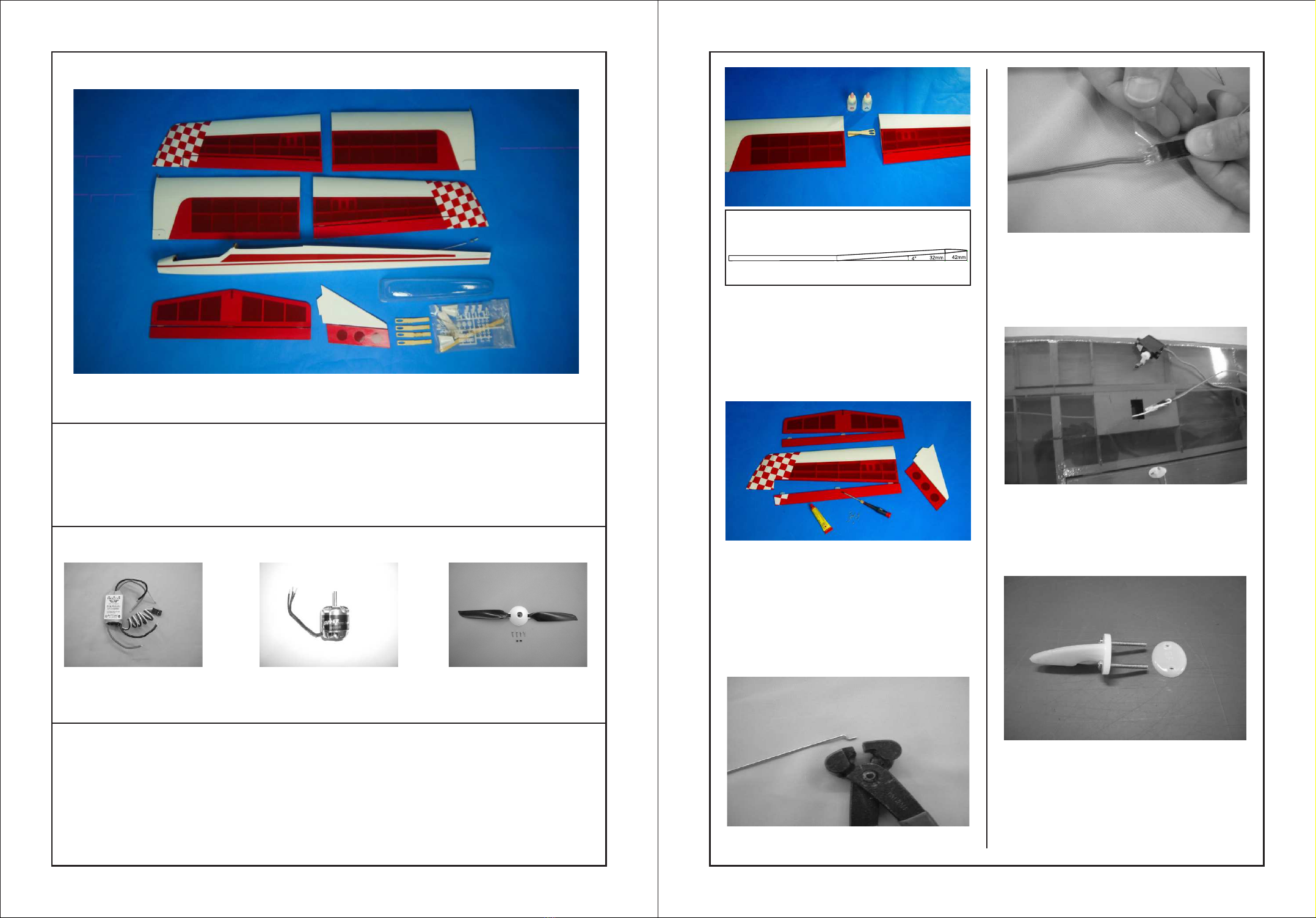
Try to fit wing joiner into each of the
wing panels. It should insert easily.
If necessary, sand the joiner until it is
achieved. Spread epoxy on both
sides of wing joiner and install the
joiner into the cavity on both wing
panels. Wipe away the excess epoxy.
Use a hobby knife to cut an opening
at the center of the wing. Pass the
extension through the hole. Apply the
transparent tape over the hole.
Mix epoxy to glue ply wing joiners on
both sides of metal wing joiner.
Clamped in place to hole the joiner
together while the epoxy cures.
Pen, make a mark on the rod where
he rod will be 5-6mm longer than the
contacting place with the servo arm.
Cut off the excess rod on the marking
place. Insert the rod into the rod
connector. Secure the rod using M3
hex screw.
be on its center position and the
fuselage must be perpendicular to the
rear edge. When satisfied with the
position, carefully mark the position
with a pen at the junction where the
horizontal meets the fuselage.
Connect the Z end on the control horn.
Center the aileron. Using a felt tipped
Use 2mm driller to drill a hole on the
aileron. Secure a control horn on this
hole.
Use hobby knife to remove the
covering out of the wing bolt holes.
Insert the wing bolt through the
washer and secure into the wing
bolt hole.
Insert a piece of 5mm silicone tube
to the thread end of the wing bolt
for avoiding missing.
Use a hobby knife to cut out the
pre-serving cooling holes on two sides
of the fuselage.
Use 2mm driller to drill a hole on the
rudder. Secure a control horn on this
hole.
Insert the rods into the out tubes.
Connect the clevis with the control
horns for both elevator and rudder.
Use 2mm driller to drill a hole on the
bottom of the elevator (near the
fuselage). Secure a control horn on
this hole.
Take 2 pieces of intake cowls from the
hardware bag and trim the edges.
It must have 2mm more on the edges
and an opening in the front.
Glue the intake cowls on cooling holes.
56
Secure the out tube for the rudder
pushrod on the top of fuselage using
CA glue. The length of the out tube is
25-30mm shorter than the rod.
Secure the out tube for the elevator
pushrod on the bottom of fuselage
using CA glue. The length of the out
tube is 25-30mm shorter than the rod.
Using a 90-degree triangle, make
sure the fin is perpendicular to the
horizontal. Use masking tape to
hold the vertical fin in place until
it's completely dry.
Use hobby knife to cut three pre-
serving slots on the bottom of the
fuselage.
Install the skid on the bottom of the
fuselage and secure it in place using
CA glue.
Use hobby knife to cut off the covering
over the holes for motor cooling hole
and screws.
Install the motor on the head of
fuselage and secure it in place using
M3x8 screws.
Place 2 pieces of 9g servos on the
servo tray. Secure them in place using
the screws.
78
Use hobby knife to cut away the
covering on the preserving cooling
holes on the top of the fuselage.
Insert the pushrods into the out tubes.
The length of the rods must be
20-25mm longer than the out tubes.
Slide the pushrod through the rod
connector. Centered the elevator and
rudde, use 1.5mm hex driver to fix the
rods. Pull the outtube straight and
secure it on F3 using CA.
The recommended center of gravity
location is from 70mm back from the
leading edge of the wing. Measured
at the location next to the fuselage.
Take the canopy and use curved
hobby scissors to trim the canopy
according to the tooling line.
Try to find the pre-serving slot on
the head of fuselage for installing
the canopy. Use hobby knife to
remove the covering out of the
slot.Use scissors to trim the
adhesive Velcro tape for applying
on the fuselage and canopy.

Popular Aircraft manuals by other brands

Safran PILATUS PC12 M19 manual

Safran

Safran PILATUS PC12 M19 manual

Dudek Coden user manual

Dudek

Dudek Coden user manual

Niviuk SKIN 3 P user manual

Niviuk

Niviuk SKIN 3 P user manual

Ikon PEAK 05 manual

Ikon

Ikon PEAK 05 manual

Navair F-14B EMERGENCY PROCEDURE TABS

Navair

Navair F-14B EMERGENCY PROCEDURE TABS

Niviuk TAKOO 5 user manual

Niviuk

Niviuk TAKOO 5 user manual

STEMME S10 manual

STEMME

STEMME S10 manual

Advance acoustic ZETA Getting started

Advance acoustic

Advance acoustic ZETA Getting started

Glider.it ASW 15 instruction manual

Glider.it

Glider.it ASW 15 instruction manual

Evector EV-97 EUROSTAR SL MICROLIGHT Maintenance manual

Evector

Evector EV-97 EUROSTAR SL MICROLIGHT Maintenance manual

Gin FALCON User Manual and Service Guide

Gin

Gin FALCON User Manual and Service Guide

Glastar GS-1 owner's manual

Glastar

Glastar GS-1 owner's manual

CrazyFly MOOWII manual

CrazyFly

CrazyFly MOOWII manual

Piper ARCHER III Pilot operating handbook

Piper

Piper ARCHER III Pilot operating handbook

RedWing RC 30cc Slick 540 manual

RedWing RC

RedWing RC 30cc Slick 540 manual

Bellanca CITABRIA 7ECA Pilots operating manual

Bellanca

Bellanca CITABRIA 7ECA Pilots operating manual

GREAT PLANES S.E.5a instruction manual

GREAT PLANES

GREAT PLANES S.E.5a instruction manual

Wipaire Wipline 3730 Service manual and instructions

Wipaire

Wipaire Wipline 3730 Service manual and instructions

manuals.online logo
manuals.online logoBrands
  • About & Mission
  • Contact us
  • Privacy Policy
  • Terms and Conditions

Copyright 2025 Manuals.Online. All Rights Reserved.