Wipaire Wipline 3730 User manual

SERVICE MANUAL & ICA
WIPLINE 3730 & 3900 FLOATS
P/N 1002551 Revision K Page 1
SERVICE MANUAL AND
INSTRUCTIONS FOR CONTINUED AIRWORTHINESS
FOR WIPLINE MODEL 3730/3900
AMPHIBIOUS AND SEAPLANE FLOATS
Revision K
WIPLINE FLOATS • SKIS • MODIFICATIONS • AIRCRAFT SALES
AVIONICS • INTERIOR • MAINTENANCE • PAINT REFINISHING

SERVICE MANUAL & ICA
WIPLINE 3730 & 3900 FLOATS
Page 2 Revision K P/N 1002551
THIS PAGE INTENTIONALLY LEFT BLANK

SERVICE MANUAL & ICA
WIPLINE 3730 & 3900 FLOATS
P/N 1002551 Revision K Page 3
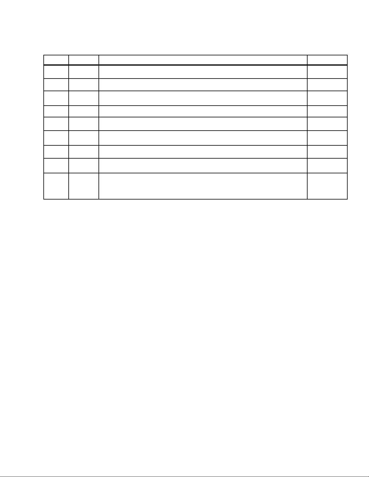
LOG OF REVISIONS
Rev Pages Description Date
A 12 Added an inspection time limit and tolerances for the Nose Block Track wear. 4/1/2006
B 4, 14-16 Updated TOC, added new inspection checklist. 2/23/2007
C&D TOC, 6-8,
16-18 Table of contents updates, expanded corrosion prevention, added steps to insp. checklist. 10/31/2008
E All Reformat of entire document, add green grease as approved grease. 4/16/2013
F 20-21 Added Shear Torque Chart, PR 1440 C Sealant and Tef-Gel, removed Warranty Claim Form. 5/26/2015
G5, 11,
20-21
Added Dow Corning DC4, Corrosion X, and Mobil Aviation Grease SHC 100 to approved
product list. Modied torque limits section. 12/4/2015
H 8 Added reference for Structural Repair Manual part number 1008274 in introduction. 5/1/2019
J11, 13, 21,
23-25
Added information about corrosion limits. Added note about STA-Lube. Added STA-Lube to
Brake Caliper Grease. Removed inspection column from Maintenance Checklist. 8/3/2020
K All
Reformatted manual in new software. Removed Comet Industries GP-730A. Removed content
in Chapter 8 and replaced with note about SRM. Removed Figures 6 through 14 as content is
found in SRM. Added note about nose box sealant and Service Letter 224. Added sections 2.6
through 2.9
2/3/2021
View most current revision of this ICA at www.wipaire.com.

SERVICE MANUAL & ICA
WIPLINE 3730 & 3900 FLOATS
Page 4 Revision K P/N 1002551
THIS PAGE INTENTIONALLY LEFT BLANK

SERVICE MANUAL & ICA
WIPLINE 3730 & 3900 FLOATS
P/N 1002551 Revision K Page 5
CONTENTS
INTRODUCTION...............................................................................................................................................7
CHAPTER 1 GENERAL INFORMATION .........................................................................................................9
CHAPTER 2 FLOAT HULL MAINTENANCE .................................................................................................11
CHAPTER 3 CORROSION .............................................................................................................................17
CHAPTER 4 HYDRAULIC SYSTEM ..............................................................................................................19
CHAPTER 5 MAIN LANDING GEAR AND RETRACTOR ............................................................................23
CHAPTER 6 NOSE GEAR AND RETRACTOR.............................................................................................29
CHAPTER 7 ELECTRICAL SYSTEM.............................................................................................................33
CHAPTER 8 REPAIRS AND MAINTENANCE...............................................................................................37
CHAPTER 9 TROUBLE SHOOTING .............................................................................................................47

SERVICE MANUAL & ICA
WIPLINE 3730 & 3900 FLOATS
Page 6 Revision K P/N 1002551
LIST OF FIGURES
FIGURE 2-1 JACK CRADLE RECOMMENDED MODIFICATION ........................................................14
FIGURE 2-2 JACKING LOCATION .........................................................................................................14
FIGURE 2-3 FLOAT SECURING LOCATIONS ......................................................................................15
FIGURE 2-4 FLOAT SECURING LOCATIONS OVERVIEW .................................................................16
FIGURE 4-1 HYDRAULIC SYSTEM 185.................................................................................................21
FIGURE 4-2 HYDRAULIC SYSTEM 206.................................................................................................22
FIGURE 5-1 LUBRICATION CHART MAIN GEAR 3730.......................................................................25
FIGURE 7-1 SCHEMATIC, LANDING GEAR ELECTRICAL SYSTEM ...............................................34
FIGURE 7-2 SCHEMATIC, LANDING GEAR ELECTRICAL SYSTEM ...............................................35

SERVICE MANUAL & ICA
WIPLINE 3730 & 3900 FLOATS
P/N 1002551 Revision K Page 7
This manual describes the general servicing and maintenance for the model 3730/3900 oat, including hull and
landing gear. For services and repairs not covered by this manual contact Wipaire Customer Service.
When performing standard repairs for Wipline Aluminum Floats, please refer to the “Structural Repair Manual For
Wipline Aluminum Floats” part number 1008274. It is available free of charge online at www.wipaire.com.
The service products referred to throughout this manual are described by their trade name and may be purchased
from Wipaire Parts Department.
To contact Wipaire for technical support or parts sales, call or email:
Wipaire, Inc.
Customer Service
1700 Henry Avenue – Fleming Field
South St. Paul, MN 55075
Phone: (651) 306-0459
Fax: (651) 306-0666
Website: www.wipaire.com
Email: [email protected]
INTRODUCTION

SERVICE MANUAL & ICA
WIPLINE 3730 & 3900 FLOATS
Page 8 Revision K P/N 1002551
THIS PAGE INTENTIONALLY LEFT BLANK

SERVICE MANUAL & ICA
WIPLINE 3730 & 3900 FLOATS
Page 10 Revision K P/N 1002551
1.0 GENERAL
The model 3730/3900 seaplane or amphibious oat is an all aluminum constructed oat with watertight
compartments. The actual displacement in fresh water for each oat is 3453 pounds buoyancy for the amphibian.
The amphibian oat is geometrically the same as the seaplane except for the addition of landing gear and internal
structure for the gear.
The water rudder system is cable operated with ball bearing pulleys. Water rudder cables tie into the existing
aircraft rudder system.
The main landing gear has a 5.00 x 5 6-ply tires and the nose landing gear has a 3.50 x 10 4-ply tire. The gear
system is hydraulically actuated and driven by two hydraulic pumps. Brakes are hydraulic and have a caliper on
each main wheel.
Steering on land is accomplished by dierential braking. The nose wheels are full castering.
Access to the oat interior is accomplished by removing covers on the top deck and covers inside the wheel well.
When necessary, water inside the oat hulls may be removed through pump out cups located on the outboard
edge of each oat top skin.

SERVICE MANUAL & ICA
WIPLINE 3730 & 3900 FLOATS
P/N 1002551 Revision K Page 11
CHAPTER 2 FLOAT HULL MAINTENANCE
CONTENTS
2.1 GENERAL..................................................................................................................................................12
2.2 HARD LANDING AND DAMAGE INVESTIGATION ...............................................................................12
2.3 CLEANING.................................................................................................................................................12
2.4 SEALING....................................................................................................................................................12
2.5 TOWING.....................................................................................................................................................13
2.6 HOISTING..................................................................................................................................................13
2.7 LEVELING .................................................................................................................................................13
2.8 JACKING PROCEDURES........................................................................................................................13
2.9 JACK REMOVAL .......................................................................................................................................16

SERVICE MANUAL & ICA
WIPLINE 3730 & 3900 FLOATS
Page 12 Revision K P/N 1002551
2.1 GENERAL
The oat structure is manufactured entirely of 6061-T6 corrosion resistant aluminum sheet and extrusions. Skins
on the inside are primed with a 3M SCOTCHWELD primer after being cleaned and acid-etched. Exterior surfaces
are cleaned and alodined. Surfaces are then primed with an epoxy-based primer and nished with enamel color
paint.
2.2 HARD LANDING AND DAMAGE INVESTIGATION
After a thorough cleaning of the suspected damaged area, all structural parts should be carefully examined to
determine the extent of damage. Frequently the force causing the initial damage is transmitted from one member
to the next causing strains and distortions. Abnormal stresses incurred by shock or impact forces on a rib,
bulkhead or similar structure may be transmitted to the extremity of the structural member, resulting in secondary
damage, such as sheared or stretched rivets, elongated bolt holes or canned skins or bulkheads. Points of
attachment should be examined carefully for distortion and security of fastenings in the primary and secondary
damaged areas at locations beyond the local damage. Inspect aircraft skins in area of oat tting attach for sign of
bending, or any other signs of damage.
2.3 CLEANING
The entire outside of the oat should be kept clean by washing with soap and water. Special care should be taken
to remove engine exhaust trail, water-line marks and barnacle type deposits. After saltwater operation, washing
with fresh water should be done daily with special attention to hard to reach places such as seams, wheel wells,
areas underneath strut covers etc. Float interior should be ushed if evidence of saltwater in compartments is
noted. The oat interior should be ushed if salt water enters the compartments; it’s easy to tell by the smell inside
the oat lockers. At night or when the oatplane is in storage, the inspection and/or baggage covers should be
opened so the interior has a chance to dry out.
THE ABOVE CLEANING TECHNIQUES ARE VITAL
FOR KEEPING CORROSION TO A MINIMUM. SALTWATER
OPERATIONS ARE STRONGLY LINKED TO
CORROSION AND MUST BE ADDRESSED PROACTIVELY.
2.4 SEALING
The oat hull has eight sealed compartments. Each compartment is equipped with a pump-out cup and inspection
cover. These compartments must be pumped out before ight and after prolonged periods of sitting in water. Each
compartment is individually sealed, as is wheel well halves and nose box. Water from one should not contaminate
the other. If leaks are found, check by lling only one compartment at a time, water will appear on outside of
hull, in adjacent compartment, nose box or wheel well. Float hull must also be inspected for leaks from damage
and sealed around nose box, nose box access cover, spreader bar, fairings, water rudder boot, baggage and
inspection covers. Refer to Products List for recommended sealants and caulk.
Note: Special attention should be taken on nose box sealant inspection. See Wipaire Service Letter 224
on the Wipaire website for details.

SERVICE MANUAL & ICA
WIPLINE 3730 & 3900 FLOATS
P/N 1002551 Revision K Page 13
2.5 TOWING
When towing the amphibian aircraft, 2 lugs are provided on the lower forward side of the nose spring.
On land, a rigid “V” frame can be fabricated to attach to these lugs for towing the aircraft with a tractor. Lake & Air
Training and Pilot Shop has this tow bar available for purchase.
On water, a rope bridle arrangement can used to tow the aircraft from the lugs described above.
2.6 HOISTING
Hoisting the aircraft can be performed using a lifting rig that attaches to the aircraft with lifting rings that are
installed at the wing attach points. If the lifting rings are not installed, reference applicable aircraft maintenance/
service manual for additional hoisting specications. Lake & Air Training and Pilot Shop has this hoisting rig
available for purchase. Contact Wipaire Customer Service for additional guidance in removal or installation of
oats.
CAUTION!
Make sure nothing is under or above the airplane or oats when hoisting the aircraft
1. Raise aircraft high enough to place oat cradle under oats as shown in Figure 2-4.
2. Lower aircraft onto oat cradle as shown in Figure 2-4.
3. Place fore and aft supports as shown in Figure 2-3 and Figure 2-4.
2.7 LEVELING
See applicable aircraft maintenance/service manual
2.8 JACKING PROCEDURES
CAUTION!
Make sure nothing is under or above the airplane or oats when jacking the aircraft.

SERVICE MANUAL & ICA
WIPLINE 3730 & 3900 FLOATS
Page 14 Revision K P/N 1002551
CAUTION!
Make sure nothing is under or above the airplane or oats when jacking the aircraft.
1. Turn o fuel.
2. Place weighted bags above the nose gear (approximately 100 lbs. on each oat to start, more may be
added as needed).
3. Position 1 person at each fore and aft of each oat, and 3 people at the jacking location of one oat.
4. Modify jack saddle of a 3 ton minimum jack by welding as shown in Figure 2-1.
FIGURE 2-1 JACK CRADLE RECOMMENDED MODIFICATION
(X = WIDTH OF CRADLE)
NOTE: This is not required and Wipaire does not have the parts for modication. It is recommended a similar
modication be performed to the jack saddle to prevent the slippage of the cradle.
1. Center cradle on saddle and position so cradle is as far aft on the main keel as possible without interfering
with main gear as it decompresses as shown in Figure 2-2.
NOTE: If desired to prevent possible cosmetic damage to oat, use material to separate cradle and oat.
FIGURE 2-2 JACKING LOCATION
1. Jack one side at a time, taking care to check the balance of the aircraft and adding more weight to the front
if needed.
2. Two people, both outboard, lift the fore and aft cradle stands up to the cradle as a 3rd person release the
pressure slowly, allowing the cradle and stands to gently contact the ground.
3. Repeat previous procedure to the other oat.

SERVICE MANUAL & ICA
WIPLINE 3730 & 3900 FLOATS
P/N 1002551 Revision K Page 15
NOTE: A smaller jack may be needed to slightly lift the oat into a high enough position for the main jack.
1. Secure oats with fore and aft supports as shown in Figure 2-3 and Figure 2-4.
FIGURE 2-3 FLOAT SECURING LOCATIONS
ALTERNATE JACKING METHOD IF WIPAIRE
JACKING FIXTURE IS NOT AVAILABLE
(8000A model shown for reference only)

SERVICE MANUAL & ICA
WIPLINE 3730 & 3900 FLOATS
Page 16 Revision K P/N 1002551
Aft Cradle
Stand
Fore Cradle
Stand Cradle
Fore
Support
Aft
Support
FIGURE 2-4 FLOAT SECURING LOCATIONS OVERVIEW
(8000A MODEL SHOWN FOR REFERENCE ONLY)
2.9 JACK REMOVAL
Make sure nothing is under or above the airplane or oats when removing the jacks from the aircraft
1. Turn o fuel.
2. Verify landing gear is in the down and locked position.
3. Verify weighted bags are still located above the nose gear.
4. Position 1 person at each fore and aft of each oat, and 1 person at the jacking location of one oat.
5. Remove all fore and aft supports as shown in Figure 2-3 and Figure 2-4.
6. Using modied jack saddle as shown in Figure 2-1, center jack saddle in center of cradle on 1 of the oats,
7. Lift aircraft to clear fore and aft cradle stands and remove fore and aft cradle stands of lifted oat.
8. Slowly lower oat to the ground, remove jack from under oat, and remove cradle from jack saddle.
9. Repeat previous procedure to the other oat.
10. Remove weighted bags from oats.

SERVICE MANUAL & ICA
WIPLINE 3730 & 3900 FLOATS
Page 18 Revision K P/N 1002551
3.0 CORROSION
Reference the Wipaire Structural Repair Manual (SRM) for allowable corrosion/material loss limits. Corrosion is
a reaction that destroys metal by an electrochemical action that converts metal to oxide. Corrosion is accelerated
when in contact with dissimilar metals such as aluminum and steel, or any material which absorbs moisture like
wood, rubber, or dirt.
The primary means of detection of corrosion is visual. The most obvious sign is a corrosive deposit of white
powder. Other signs are discoloration of the metal surface or bubbles and blisters under the painted surface. Light
corrosion may be removed by light hand sanding or chromic acid. Moderate and severe corrosion (blistering,
aking, and pitting) may be removed by heavy sanding or grinding, and applying chromic acid. No more than
1/3rd the thickness of skin material should be removed before complete replacement or reinforcement of an area
is necessary.
After removing the corroded area, restore area to original nish (prime and enamel). BOESHIELD T9, Corrosion
X, or ACF-50 may also be applied to stop corrosion. Refer to manufacturer’s instructions for application
instructions.
Maintaining the oat inside and outside nishes by washing after saltwater operations will help protect the oat
from corrosion. Periodically, all hardware should be covered with a waterproof grease, or paralketone. Under
saltwater conditions, bolts should be removed at least once a year and grease reapplied to the shafts, heads and
nuts.
THE ABOVE TECHNIQUES ARE VITAL
FOR KEEPING CORROSION TO A MINIMUM. SALTWATER
OPERATIONS ARE STRONGLY LINKED TO
CORROSION AND MUST BE ADDRESSED PROACTIVELY.

SERVICE MANUAL & ICA
WIPLINE 3730 & 3900 FLOATS
P/N 1002551 Revision K Page 19
CHAPTER 4 HYDRAULIC SYSTEM
CONTENTS
4.1 OPERATION ..............................................................................................................................................20
4.2 MAINTENANCE ........................................................................................................................................20
4.3 BLEEDING THE SYSTEM........................................................................................................................20

SERVICE MANUAL & ICA
WIPLINE 3730 & 3900 FLOATS
Page 20 Revision K P/N 1002551
4.1 OPERATION
The hydraulic system consists of an electro-hydraulic power pack with a non-reversing type pump and a hand
pump backup tied in between the return and pressure lines (see hydraulic schematic in gures 3 & 4). The pump
and reservoir assembly is mounted in the left oat.
A pressure of between 500 psi and 1000 psi is maintained in the supply line. When the pressure falls below 500
psi, a pressure switch will activate the pump solenoid, providing power to the pump. When the pressure reaches
1000 psi, the pressure switch deactivates the solenoid and the pump motor is stopped. Figures 1 & 2 show the
electrical schematic of the system. A check valve on the output side of the pump retains pressure in the system
while the pump is o. The pump has an internal relief valve which directs oil back to the pump reservoir when the
line pressure exceeds 1200 psi. The system also has an external relief valve to protect against thermal expansion
when line pressure exceeds 1900 psi.
The selection of gear-up or gear-down is accomplished by a cockpit mounted control valve. Each oat gear has
individual indicator lights on the control valve allowing the pilot to conrm that each gear has fully retracted or
extended.
4.2 MAINTENANCE
Maintenance of the hydraulic system is very easy; keep the proper amount of oil in the reservoir. A sight glass is
provided for this and the level should be kept in the upper 1/3 of the range. A screen is located in the reservoir
tank around the uid pick up pipe and can be cleaned or checked at annual inspection or every 100-hour. Check
and replace if oil is dirty or if moisture is found (MIL-H-5601 Hydraulic Fluid, RED).
4.3 BLEEDING THE SYSTEM
Simply ll the reservoir with hydraulic oil and start a gear cycle. If the reservoir empties (i.e. uid goes out of sight
in the sight glass), stop the cycle and add oil and complete the cycle. Continue with approximately four more gear
cycles after the uid level in the reservoir normalizes (it will vary in level between up and down positions) and
check for leaks.
This manual suits for next models
1
Table of contents
Other Wipaire Aircraft manuals

Wipaire
Wipaire Wipline 2100 User manual

Wipaire
Wipaire 8750 User manual

Wipaire
Wipaire WIPLINE 10000 User manual

Wipaire
Wipaire Wipline 4000 User manual

Wipaire
Wipaire WIPLINE 13000 User manual

Wipaire
Wipaire WIPLINE 8000 User manual

Wipaire
Wipaire AT-802 User manual

Wipaire
Wipaire 8750 User manual

Wipaire
Wipaire WIPLINE 7000 User manual