GREAT PLANES S.E.5a User manual

WARRANTY
Great Planes®Model Manufacturing Co. guarantees this kit to be free from defects in both material and workmanship at the date of purchase.
This warranty does not cover any component parts damaged by use or modification. In no case shall Great Planes’ liability exceed the
original cost of the purchased kit. Further, Great Planes reserves the right to change or modify this warranty without notice.
In that Great Planes has no control over the final assembly or material used for final assembly, no liability shall be assumed nor accepted for
any damage resulting from the use by the user of the final user-assembled product. By the act of using the user-assembled product, the user
accepts all resulting liability.
If the buyer is not prepared to accept the liability associated with the use of this product, the buyer is advised to return this kit
immediately in new and unused condition to the place of purchase.
To make a warranty claim send the defective part or item to Hobby Services at the address below:
Hobby Services
3002 N. Apollo Dr., Suite 1
Champaign, IL 61822
USA
Include a letter stating your name, return shipping address, as much contact information as possible (daytime telephone number, fax number,
e-mail address), a detailed description of the problem and a photocopy of the purchase receipt. Upon receipt of the package the problem will
be evaluated as quickly as possible.
READ THROUGH THIS MANUAL BEFORE STARTING
CONSTRUCTION.IT CONTAINS IMPORTANT INSTRUCTIONS
AND WARNINGS CONCERNING THE ASSEMBLY AND
USE OF THIS MODEL.
GPMZ1140 for GPMA1140 V1.0Entire Contents © Copyright 2006
Champaign, Illinois
(217) 398-8970, Ext 5
INSTRUCTION MANUAL
Wingspan: 34 in [864mm]
Wing Area: 420 sq in [27.1dm2]
Weight: 1.3 – 1.5 lb [595 – 680g]
Wing Loading: 7.5 – 8.2 oz/sq ft [22 – 25g/dm2]
Length: 25.5 in [648mm]
Required (not included):
Radio: 4-channel with four micro servos
Motor: ElectriFly™RimFire™28-30-950 brushless (not included)
ESC: ElectriFly SS-25 (not included)
Battery: 11.1V, 1250mAh LiPo
™

2
INTRODUCTION ...............................................................2
AMA...................................................................................2
SAFETY PRECAUTIONS..................................................2
BATTERY CHARGER OPTIONS......................................3
ADDITIONAL ITEMS REQUIRED.....................................3
Hardware & Accessories.............................................3
Adhesives & Building Supplies....................................3
Optional Supplies & Tools ...........................................3
IMPORTANT BUILDING NOTES......................................4
COMMON ABBREVIATIONS............................................4
ORDERING REPLACEMENT PARTS ..............................4
METRIC/INCH RULER......................................................4
KIT INSPECTION..............................................................5
KIT CONTENTS ................................................................5
PREPARATIONS...............................................................6
ASSEMBLE THE WING ....................................................6
Install the Ailerons.......................................................6
ASSEMBLE THE FUSELAGE...........................................6
Mount the Wing...........................................................6
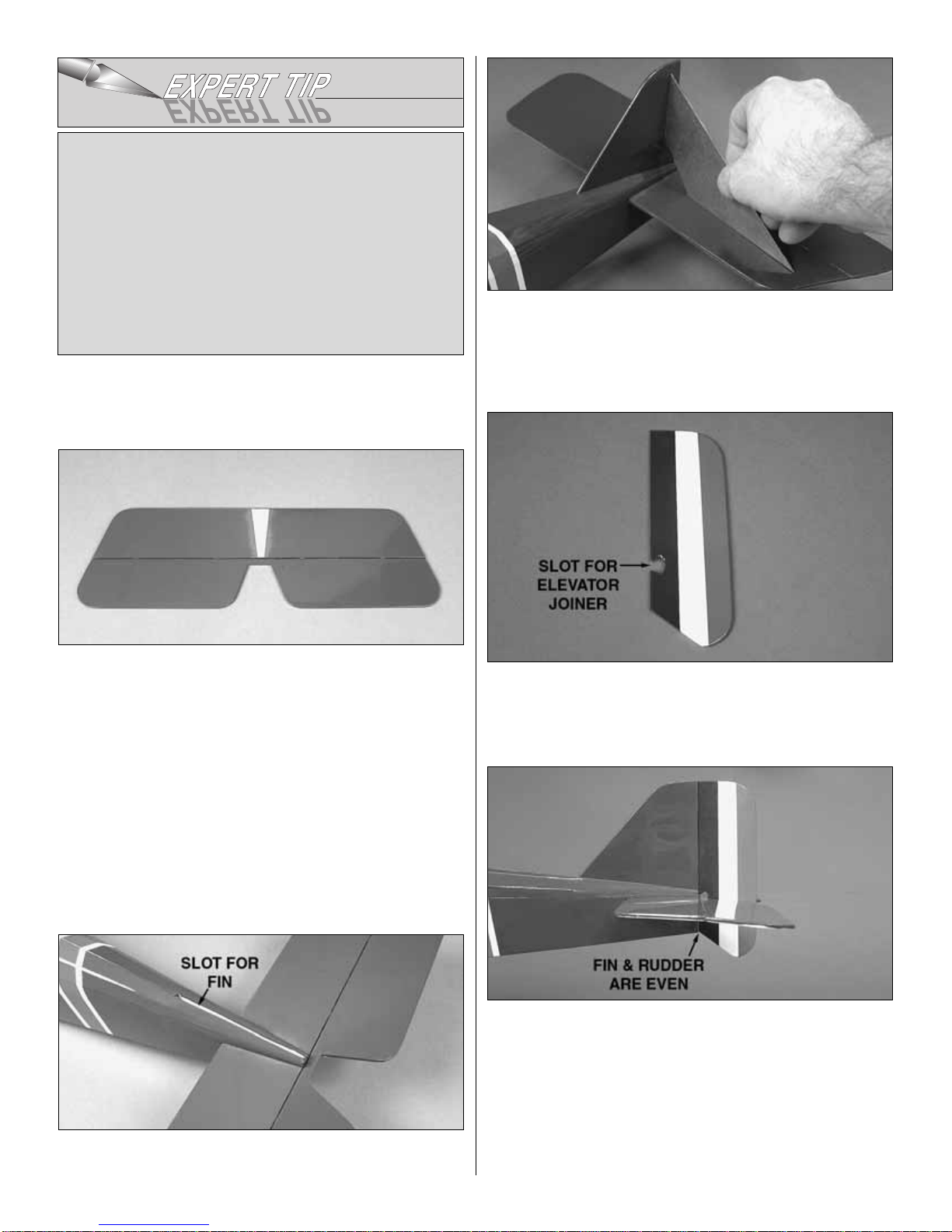
Mount the Stabilizer & Fin...........................................7
RADIO INSTALLATION.....................................................9
Install the Motor & ESC.................................................9
Install the Control Horns............................................10
Install the Servos.......................................................11
Install the Top Wing...................................................12
FINISH THE MODEL.......................................................14
GET THE MODEL READY TO FLY.................................16
Check the Control Directions ....................................16
Set the Control Throws..............................................16
Balance the Model (C.G.)..........................................16
Balance the Model Laterally......................................17
PREFLIGHT.....................................................................17
Identify Your Model....................................................17
Charge the Transmitter Batteries...............................17
Balance the Propellers..............................................17
Proper Care of Your Motor.........................................18
Ground Check ...........................................................18
Range Check.............................................................18
MOTOR & BATTERY SAFETY PRECAUTIONS ............18
AMA SAFETY CODE (excerpts)....................................18
CHECK LIST ...................................................................19
FLYING ............................................................................19
Takeoff.......................................................................19
Flight..........................................................................20
Landing......................................................................20
The S.E.5a is one of the most recognizable and popular of
all the WW1 Biplanes.You can now have this great looking
and flying aircraft as an electric without the mess and fuss
of a glow engine. With today’s LiPo batteries and micro
servos, small electrics have become very popular. Now
Great Planes brings you the S.E.5a in a small, easy to fly,
ARF electric. So if you want to impress your glow flying
buddies with an electric, the Great Planes S.E.5a EP ARF is
just what you need.
For the latest technical updates or manual corrections to the
S.E.5a EP ARF, visit the Great Planes web site at
www.greatplanes.com. Open the “Airplanes” link and
select the S.E.5a EP ARF. If there is new technical
information or changes to this model a “tech notice” box will
appear in the upper left corner of the page.
We urge you to join the AMA (Academy of Model
Aeronautics) and a local R/C club.The AMA is the governing
body of model aviation and membership is required to fly at
AMA clubs.Though joining the AMA provides many benefits,
one of the primary reasons to join is liability protection.
Coverage is not limited to flying at contests or on the club
field. It even applies to flying at public demonstrations and
air shows. Failure to comply with the Safety Code (excerpts
printed in the back of the manual) may endanger insurance
coverage.Additionally, training programs and instructors are
available at AMA club sites to help you get started the right
way. There are over 2,500 AMA chartered clubs across the
country. Contact the AMA at the address or toll-free phone
number below.
IMPORTANT!!! Two of the most important things you can do
to preserve the radio controlled aircraft hobby are to avoid
flying near full-scale aircraft and avoid flying near or over
groups of people.
1.Your S.E.5a EP ARF should not be considered a toy, but
rather a sophisticated, working model that functions very
much like a full-size airplane. Because of its performance
capabilities, the S.E.5a EP ARF, if not assembled and
operated correctly, could possibly cause injury to yourself or
spectators and damage to property.
PROTECTYOUR MODEL,YOURSELF
& OTHERS...FOLLOW THESE
IMPORTANT SAFETY PRECAUTIONS
Academy of Model Aeronautics
5151 East Memorial Drive
Muncie, IN 47302
Tele: (800) 435-9262
Fax (765) 741-0057
Or via the Internet at:
http://www.modelaircraft.org
AMA
INTRODUCTION
TABLE OF CONTENTS

2. You must assemble the model according to the
instructions. Do not alter or modify the model, as doing so
may result in an unsafe or unflyable model. In a few cases
the instructions may differ slightly from the photos. In those
instances the written instructions should be considered
as correct.
3.You must take time to build straight, true and strong.
4. You must use an R/C radio system that is in first-
class condition.
5.You must correctly install all R/C and other components so
that the model operates correctly on the ground and in the air.
6.You must check the operation of the model before every
flight to insure that all equipment is operating and that the
model has remained structurally sound. Be sure to check
clevises or other connectors often and replace them if they
show any signs of wear or fatigue.
7. If you are not an experienced pilot or have not flown this
type of model before, we recommend that you get the
assistance of an experienced pilot in your R/C club for your
first flights.If you’re not a member of a club, your local hobby
shop has information about clubs in your area whose
membership includes experienced pilots.
Remember:Take your time and follow the instructions to
end up with a well-built model that is straight and true.
The Great Planes S.E.5a EP ARF is designed for use with
LiPo batteries only. All LiPo batteries require a charger
specifically designed for charging LiPo batteries.The use of
a charger not designed for charging LiPo batteries will result
in damage to the batteries and possibly a fire.
We recommend the use of the Great Planes Triton™DC
Peak Charger (GPMM3150), the ElectriFly™DC PolyCharge™
(GPMM3010) or for charging more than one battery at a
time the ElectriFly PolyCharge4 (GPMM3015).
In addition to the items listed in the “
BATTERY CHARGER
OPTIONS”
section, the following is the list of hardware and
accessories required to finish the S.E.5a EP ARF. Order
numbers are provided in parentheses.
❏4-Channel radio with four micro servos
❏(1) ElectriFly SS-25 25 amp brushless ESC (GPMM1820)
❏(1) ElectriFly 3.5mm Bullet™(male) to 2mm Bullet
(female) connector adapter (GPMM3122)
❏(1) ElectriFly 1250mAh LiPo 3-cell battery (GPMP0823)
❏(1) Futaba®R114F 4-channel FM receiver
(FUTL0443, FUTL0442)
❏(2) 12" [305mm] Futaba extensions (FUTM4507)
❏(1) Futaba “Y-harness” (FUTM4130)
❏(1) ElectriFly RimFire C28-30-950 brushless
motor (GPMG4560)
❏(1) 10x4.5 Prop (GPMQ6660)
❏(1) 3mm Prop adapter (GPMQ4959)
In addition to common household tools and hobby tools, this
is the“short list”of the most important items required to build
the S.E.5a EP ARF.
Great Planes Pro™CA and Epoxy glue
are recommended.
❏1 oz. [28g] Thin Pro CA (GPMR6002)
❏#1 Hobby knife (HCAR0105)
❏#11 Blades (5-pack, HCAR0211)
❏Medium T-pins (100, HCAR5150)
❏Builder’s Triangle Set (HCAR0480)
❏K & S #801 Kevlar®thread or string (for stab alignment)
❏Pliers
❏Wire cutter
❏Top Flite®MonoKote®heat gun (TOPR2000)
❏Clear tape
Here is a list of optional tools mentioned in the manual that
will help you build the S.E.5a EP ARF.
❏Stick-on segmented lead weights (GPMQ4485)
❏Top Flite MonoKote sealing iron (TOPR2100)
❏Top Flite Hot Sock™iron cover (TOPR2175)
❏2 oz. [57g] Spray CA activator (GPMR6035)
❏CA applicator tips (HCAR3780)
❏CA debonder (GPMR6039)
❏Robart Super Stand II (ROBP1402)
❏CG Machine™(GPMR2400)
❏Precision Magnetic Prop Balancer™(TOPQ5700)
Optional Supplies & Tools
Adhesives & Building Supplies
Hardware & Accessories
ADDITIONAL ITEMS REQUIRED
BATTERY CHARGER OPTIONS
We, as the kit manufacturer, provide you with a top quality,
thoroughly tested kit and instructions, but ultimately the
quality and flyability of your finished model depends on
how you build it; therefore, we cannot in any way
guarantee the performance of your completed model, and
no representations are expressed or implied as to the
performance or safety of your completed model.
3

• When you see the term
test fit
in the instructions, it means
that you should first position the part on the assembly
without using any glue, and then slightly modify or
custom fit
the part as necessary for the best fit.
•
Photos
and
sketches
are placed before the step they
refer to. Frequently you can study photos in following
steps to get another view of the same parts.
• The stabilizer and wing incidences and motor thrust
angles have been factory-built into this model.However,
some technically-minded modelers may wish to check
these measurements anyway. To view this information
visit the web site at www.greatplanes.com and click on
“Technical Data.” Due to manufacturing tolerances
which will have little or no effect on the way your model
will fly, please expect slight deviations between your
model and the published values.
Fuse = Fuselage
Stab = Horizontal Stabilizer
Fin = Vertical Fin
LE = Leading Edge
TE = Trailing Edge
LG = Landing Gear
Ply = Plywood
" = Inches
mm = Millimeters
ESC = Electronic Speed Control
Replacement parts for the Great Planes S.E.5a EP ARF are
available using the order numbers in the Replacement Parts
List that follows.The fastest, most economical service can be
provided by your hobby dealer or mail-order company.
To locate a hobby dealer, visit the Hobbico®web site at
www.hobbico.com. Choose “Where to Buy” at the bottom
of the menu on the left side of the page. Follow the
instructions provided on the page to locate a U.S., Canadian
or International dealer.
Parts may also be ordered directly from Hobby Services by
calling (217) 398-0007, or via facsimile at (217) 398-7721,
but full retail prices and shipping and handling charges will
apply. Illinois and Nevada residents will also be charged
sales tax. If ordering via fax, include a Visa®or MasterCard®
number and expiration date for payment.
Mail parts orders and payments by personal check to:
Hobby Services
3002 N. Apollo Drive, Suite 1
Champaign, IL 61822
Be certain to specify the order number exactly as listed in
the Replacement Parts List. Payment by credit card or
personal check only; no C.O.D.
Ifadditionalassistanceis required foranyreasoncontactProduct
telephone at (217) 398-8970.
Description How to Purchase
Missing pieces Contact Product Support
Instruction manual Contact Product Support
Kit parts listed below Hobby Supplier
Replacement Parts List
GPMA3000..............Upper Wing Set
GPMA3001..............Lower Wing Set
GPMA3002..............Fuse Set
GPMA3003..............Tail Surface Set
GPMA3004..............Cowl
GPMA3005..............Cabanes Set
GPMA3006..............Interplane Set
GPMA3007..............Machine Gun Set
GPMA3008..............Exhaust Stack Set
GPMA3009..............Landing Gear
GPMA3010..............Wheels (2)
GPMA3011..............Pilot
ORDERING REPLACEMENT PARTS
COMMON ABBREVIATIONS
IMPORTANT BUILDING NOTES
4
To convert inches to millimeters, multiply inches by 25.4

5
Before starting to build, take an inventory of this kit to make sure it is complete, and inspect the parts to make sure they
are of acceptable quality. If any parts are missing or are not of acceptable quality, or if you need assistance with assembly,
contact Product Support. When reporting defective or missing parts, use the part names exactly as they are written in
the Kit Contents list.
Great Planes Product Support
3002 N. Apollo Drive, Suite 1
Champaign, IL 61822
Telephone: (217) 398-8970, ext. 5
Fax: (217) 398-7721
E-mail: [email protected]
KIT INSPECTION
1. Radiator
2. Fuselage
3. Battery Hatch
4. Hook & Loop Material
5. Exhaust (L&R)
6. Machine Gun
7. Outer Wing Struts (2 long, 2 short)
8. Long Cabanes (2)
9. Short Cabanes (2)
10. Landing Gear Supports (2)
11. Main Landing Gear
12. Stabilizer & Elevator
13. Fin & Rudder
14. Top Wing
15. Bottom Wing
(3) 3 x 6mm Machine Screws
(8) 2 x 7mm Self-Tapping Screws
(4) 35mm Aileron Pushrod
(4) 25mm Heat-Shrink Tubing
(4) #1 Strut Mounts
(2) #2 Strut Mounts
(2) #3 Strut Mounts
(1) Plywood Motor Mount
(3) Aluminum Tubes
(3) 3 x 26mm Machine Screws
(7) 3mm Washers
(2) 460mm Pushrods
(4) Control Horns
(2) Screw-Lock Pushrod Connectors
(2) Screw-Lock Nylon Retainers
(1) Double-Sided Tape
(2) Aileron Servo Hatch
(1) 3 x 18mm Machine Screw
(4) Straight Control Horn
(1) Hook & Loop Material
(14) 2 x 8mm Self-Tapping Washer
Head Screw
(2) 100mm Pushrod Z-Bend One End
(2) 100mm Pushrod L-Bend One End
(2) Plastic Pushrod Retainer
(2) 2 x 9mm Machine Screw
(2) 2mm Washer
(2) 2 x 5mm Flat Head Machine Screw
Kit Contents (photographed)
Kit Contents (not photographed)
KIT CONTENTS
2
15
1
37
5
89
12
13
14
10
11
6
4

❏1. If you have not done so already, remove the major
parts of the kit from the box (wing, fuselage, tail parts, etc.)
and inspect them for damage. If any parts are damaged or
missing, contact Product Support at the address or
telephone number on page 5.
❏2. Separate the ailerons from the wing, the rudder from
the fin and the elevator from the stabilizer. If necessary, use
a covering iron set on medium/high to carefully tighten the
covering. Lay the control surface on a flat surface and apply
pressure over sheeted areas to thoroughly bond the
covering to the wood. Hint: Poke three or four pin holes in
the covering over the open structure in the tail surfaces.This
will allow the hot air to escape while tightening the covering.
Warning: Do not over shrink the covering or it will cause
the control surfaces to twist.
❏❏1.Test fit the right aileron to the bottom wing with two
6.4 x 15mm hinges.If the hinges don’t stay centered, stick a
pin through the middle of the hinges to hold them in position
while fitting the aileron to the wing.
❏❏2. Remove any pins you may have inserted into the
hinges. Adjust the aileron so there is a very small gap
between the LE of the aileron and the wing.The gap should
be small – just enough to see light through or to slip a piece
of paper through.
❏❏3. Apply three drops of thin CA to the top and bottom of
each hinge. Do not use CA accelerator. After the CA has
cured, test the hinges by pulling on the ailerons.
❏4. Now join the other aileron to the bottom wing using the
same procedure.
❏5. Repeat the process of installing the ailerons on the
top wing.
❏1. Trim the covering from the bolt hole at the TE of the
bottom wing.
❏2.Test fit the wing to the fuselage and bolt it into position
with a 3 x 18mm machine screw and 3mm washer.
Mount the Wing
ASSEMBLE THE FUSELAGE
Install the Ailerons
ASSEMBLE THE WING
PREPARATIONS
6

❏1. Using a sharp hobby knife, remove the covering from
the stabilizer slot at the aft end of the fuselage. Also remove
the temporary balsa block.
❏2. Mark the center of the TE of the stabilizer. Insert the
stabilizer into the slot.
❏3.Stick aT-pin into the center of the top of the firewall.Tie
a small loop in one end of a 900mm piece of non-elastic
string such as K&S #801 Kevlar thread. Slip the loop in the
string over the T-pin.
❏4. Fold a piece of masking tape over the other end of the
string and draw an arrow on it.With the stab centered on the
fuselage and the TE of the stabilizer flush with the aft end of
the fuse, slide the tape along the string and align the arrow
with one tip of the stab. Swing the string over to the same
position at the other end of the stab. If the arrow doesn’t
align with the tip, adjust the stab and the arrow slightly and
check both tips again.Adjust the stab until the stabilizer tips
and the TE are centered.
❏5. View the stab from approximately 3m behind the plane.
Check that the stab is parallel with the wing. If it is not, lightly
sand the stab saddle until the stab is parallel with the wing.
❏6. Use a fine-point felt-tip pen to mark the outline of the
fuselage onto the bottom and top of the stab.
❏7. Remove the stab from the fuselage. Use a sharp #11
hobby knife or the “
Expert Tip”
that follows to cut the
covering from the stab just inside the lines you marked.Use
care to cut only the covering and not the wood. Cutting the
wood will weaken the stab and it may break in flight.
Mount the Stabilizer & Fin
7

❏8. Temporarily attach the elevator to the stabilizer with
four CA hinges. Make sure the stabilizer and elevator are
aligned. If needed, use T-pins to hold the CA hinges
centered in the elevator. Apply 3 drops of thin CA on the top
and bottom of each hinge.
❏9. Reinstall the stabilizer in the fuselage. Use the string
method to align the stabilizer.Then, glue the stabilizer to the
fuselage with thin CA.
❏10. Cut the covering from over the slot in the fuselage for
the fin.
❏11. Test fit the fin in the fuselage. Make sure that the fin
is perpendicular to the stabilizer and the TE is flush with the
aft end of the fuselage.
❏12. Trim the covering from over the slot in the LE of
the rudder.
❏13.Install three CA hinges in the rudder and test fit it on the
fin. Adjust the position of the fin so that the bottom of the
rudder is even with the bottom of the fuselage and the LE of
the rudder and the TE of the fin are aligned.
❏14. Use a fine-point felt-tip pen to mark the outline of the
fuselage onto each side of the fin.
HOW TO CUT COVERING FROM BALSA
Use a 25-watt soldering iron to cut the covering from the
stab.The tip of the soldering iron doesn’t have to be sharp,
but a fine-tip does work best. Allow the iron to heat fully.
Use a metal straightedge to guide the soldering iron at a
rate that will just melt the covering and not burn into the
wood. The hotter the soldering iron, the faster it must
travel to melt a fine cut. Allow the heat to melt the
covering.Do not apply much pressure or the wood may be
damaged. Peel off the covering.
8

❏15. Remove the fin from the fuselage. Use a sharp #11
hobby knife or the
“Expert Tip”
on page 8 to cut the
covering from the fin just inside the lines you marked. Use
care to cut only the covering and not the wood. Cutting the
wood will weaken the fin and it may break in flight.
❏16. Reinstall the fin and rudder. Check that everything is
aligned. Then, use thin CA to glue the fin in the fuselage.
Also use thin CA to glue the three CA hinges, centered in
the fin and rudder.
❏17. Cut the covering from over the two tail skid mounting
holes on the bottom of the fuselage.
❏18.Attach the tail skid to the bottom of the fuselage using
thin CA.
Note: You will need to have your motor battery charged later in
this section. We recommend that you start charging it now so
you do not have to wait for it to charge later.Make sure to closely
follow the charging instructions for charging LiPo batteries.
❏1.Cut a 20mm long piece of hook and loop material.Glue the
20mm soft piece (hook side) to the back of the ESC. Glue the
rough piece (loop side) to the top of the inside of the fuselage.
Insert the ESC through the front of the firewall.Route the battery
connector out of one of the two holes at the back of the battery
compartment. Route the servo lead into the wing opening and
the three motor leads out the front of the firewall.The reason the
ESC needs to be mounted in this location is so that it has a good
flow of air over it.
❏2.Attach the RimFire motor to the back of the plywood motor
mount with three 3 x 6mm machine screws. Apply a drop of
threadlocker on the threads of the machine screws.
Install the Motor & ESC
RADIO INSTALLATION
9

❏3. Place a 3mm washer over each of the three 3 x 26mm
motor mount machine screws. Apply a drop of Threadlocker
on the threads of each screw and install the motor mount to
the firewall.
❏4. Install a 3.5mm Bullet (male) to 2mm Bullet (female)
connector adapter (GPMM3122) on each of the motor leads.
Connect the motor leads to the ESC.Then, stuff the wires into
the fuselage to prevent them from contacting the rotating
motor case.
❏1. Insert the two 460mm wire pushrods into the outer
pushrod tubes inside the fuselage. Notice at the aft end of
the fuselage where the pushrods press against the covering.
Using a sharp hobby knife, cut a small slot in the covering to
allow the pushrod to exit the fuselage.
❏❏2. Use a sharp hobby knife to trim the covering from
over the small rectangular hole towards the LE of the rudder.
Do not cut all the way through the rudder. Test fit a control
horn in the hole.
❏❏3. Insert the Z-bend of the 460mm pushrod into the
outer hole of the control horn.
❏❏4. Insert the pushrod in the pushrod hole on the left side
of the fuselage. Insert the control horn in the rudder and
position it so that the pushrod holes are aligned with the rudder
hinge line. Use CA to secure the control horn to the rudder.
Install the Control Horns
10

❏5. Install the elevator control horn following the
same procedure.
❏1.Install the grommets and servo arms on the rudder and
elevator servos. Trim off the unused servo arms. Insert a
screw-lock pushrod connector in the hole of each servo arm
8.7mm from the center of the servo. Secure the screw-lock
pushrod connector to the servo arm with a nylon retainer.
❏2. Plug the ESC, rudder and elevator servos into the
receiver.Switch on the transmitter and then the ESC.Center
the trims on the transmitter.Then, center the servo arms on
the servos so that the arm is perpendicular to the centerline
of the servo. Insert the rudder and elevator pushrod wires in
screw-lock pushrod connectors and install the rudder and
elevator servos on the servo rails. Use the hardware
included with the servos to mount the servos to the rails.
❏3.Switch on the transmitter and the ESC.Center the elevator
servo trim and the elevator.Tighten the set screw, in the screw-
lock pushrod connector, against the elevator pushrod.
❏4.Plug aY-harness into the aileron socket of the receiver.
Attach the double-sided tape to the back of the receiver and
mount the receiver to the back of the front radio
compartment former. Be careful to not cover the two cooling
holes in the former.
❏5.Follow the same procedure to connect the rudder pushrod.
❏❏6.Trim the covering from over the pushrod exit on the
aileron servo hatch.
❏❏7. Plug one of the aileron servos into the aileron
Y-harness. Switch on the transmitter and ESC and center
the aileron trim and the servo. Trim the unused arms from
the servo arm.
❏❏8.Clean the servo case with denatured alcohol.Use CA to
glue the aileron servo on the bottom of the aileron servo hatch
so that the servo arm is centered in the opening. If you prefer,
wrap electrical tape or heat-shrink tubing around the servo
before gluing it to the servo hatch.This will allow the servo to be
easily removed.
Install the Servos
11

❏❏9. Connect a 305mm servo extension to the aileron
servo. Use heat-shrink tubing or electrical tape around the
connection to prevent it from coming loose.Tie the string that
is located in the aileron servo bay to the end of the extension
and pull the wire through the wing and out the center.
❏❏10.Secure the aileron servo hatch to the wing with four
2 x 7mm self-tapping screws.
❏❏11. Trim the covering from over the control horn slot.
Insert a control horn and glue it with thin CA.
❏❏12. Install a 35mm aileron pushrod in the outer hole of
aileron servo arm and the outer hole of the aileron control
horn. Slide a 25mm piece of heat-shrink tubing over the
pushrods. With the radio system on and the aileron
centered, shrink the heat-shrink tubing over the pushrods
and apply a couple of drops of thin CA to the joint. Note: A
heat gun or the shaft of a hot soldering iron works great for
shrinking the heat-shrink tubing.
❏13. Follow the same procedure to install the other
aileron servo.
❏14. Make a small hole in the bottom sheeting. Route the
antenna out of the hole and tape it to the bottom of the fuselage.
Note: Dry fit the strut mounts to make sure they are in
the correct location.
❏1. On the top of the bottom wing, trim the covering from
over the four strut mount pockets. Note that there are eight
plywood strut mounts. Four are labeled #1, two are labeled
#2 and two are labeled #3. Insert the #3’s in the forward
pockets of the bottom wing and the #2’s in the aft pockets of
the bottom wing. Also note that the lips on the mounts are
angled to match the wing ribs.
❏2. Install the four #1 strut mounts in the bottom of the top
wing following the same procedure.
Install the Top Wing
12

❏3.Trim the covering from over the four slots at the aft edge
of the ailerons on the top and bottom wing. Insert a straight
control horn in each slot. The control horn should be
centered on the TE of the aileron. Secure the control horns
with thin CA.
❏4. Take the two pieces of hook and loop material and
overlap them by 38mm.
❏5. Route the hook and loop material through one of the
slots in the battery compartment and back out the other slot.
❏6. Bolt the bottom wing back on the fuselage. Make sure
the ailerons servos are plugged into the receiver.
❏7.Use CA to glue the machine gun to the top of the fuselage.
❏8.The S.E.5a EP ARF comes with two long and two short
outer wing struts. Attach the short struts to the forward strut
mounts of the bottom wing using 2 x 8mm self-tapping
washer head screws. Attach the long struts to the aft strut
mounts. Do not tighten the wing struts completely.
❏9. Trim the covering from over the openings for the
cabanes, on both sides of the fuselage.
13

❏10. Insert the two short cabanes in the forward slots and
the long cabanes in the aft slots as shown.
❏11.Attach the top wing to the cabanes and the outer wing
struts with eight 2 x 8mm self-tapping washer head screws.
Once you have determined that the strut mounts are in the
correct location, use thin CA to glue them in the wing.
❏❏12. Install a 100mm pushrod with the Z-bend at one
end in the control horn of the bottom wing aileron.
❏❏13. Install the 100mm pushrod with the L-bend in the
control horn of the top wing’s aileron. Secure it with a white
plastic retainer.
❏❏14.Switch the radio system on.Make sure the ailerons are
centered.Tape the top wing aileron in the neutral position.
❏❏15. Slide a 2.5 x 25mm piece of heat-shrink tubing over
both pushrods with both the top and bottom ailerons centered.
Shrink the heat-shrink tubing over the pushrods with a soldering
iron and apply a couple of drops of thin CA to the joint.
❏16. Install the second set of pushrods between the other
set of ailerons.
❏1. Attach the main landing gear using two 2 x 9mm
machine screws and two 2mm flat washers. The landing
gear should be positioned so that it is leaning forward. Do
not fully tighten the screws.
❏2. Attach the landing gear supports to the main landing gear
using two 2 x 5mm flat head screws. Do not tighten the screws.
FINISH THE MODEL
14

❏3.Attach the other end of the landing gear supports to the
bottom of the wing with two 2 x 8mm washer head self-
tapping screws. Once all the screws are installed they can
be tightened.
❏4. Glue the exhaust to the side of the fuselage.
❏5. Slide the prop shaft and collet onto the output shaft of
the gear-drive.The collet has a tapered hole through it.The
side with the larger hole goes on first. Use clear tape to
attach the radiator to the front of the fuselage so that the
prop adapter is centered in the opening of the radiator.
❏6.Remove the prop nut and washer and install the 10x4.5
propeller. Reinstall the washer and prop nut and tighten the
nut securely.
❏7. Insert the battery in the battery compartment and
secure it with the hook and loop material. Trim the excess
hook and loop material.
❏8. Slide the battery hatch into position. Note that the lip
slides under the front of the fuselage and the aft end is held
on with two magnets.
15

Warning: Once the motor battery is connected to the ESC,
stay clear of the propeller.
❏1.Switch on the transmitter and connect the motor battery to
the ESC. Move the throttle stick down to the off position.Switch
on the ESC and center the trims.
❏2. Make certain that the control surfaces respond in the
correct direction as shown in the diagram. If any of the
controls respond in the wrong direction, use the servo
reversing in the transmitter to reverse the servos connected
to those controls. Be certain the control surfaces have
remained centered. Adjust if necessary.
❏3. Follow the instructions included with your ESC to arm
the motor. Make sure the propeller is turning in the correct
direction. If not, refer to the ESC instructions to change the
direction of rotation.
Warning! Once the battery is connected to the ESC, stay
clear of the propeller even if the ESC has not been armed.
Use a Great Planes AccuThrow (or a ruler) to accurately
measure and set the control throw of each control surface as
indicated in the chart that follows.If your radio does not have
dual rates, we recommend setting the throws at the low
rate setting.
Note: The throws are measured at the widest part of the
elevators, rudder and ailerons.
At this stage the model should be in ready-to-fly condition
with all of the systems in place including the motor, landing
gear, motor battery, and the radio system.
❏1.Use a felt-tip pen or 3mm-wide tape to accurately mark
the C.G. on the bottom of the top wing on both sides of the
fuselage. The C.G. is located 2-1/2" [64mm] back from the
LE of the top wing.
This is where your model should balance for the first
flights. Later, you may wish to experiment by shifting the
C.G. up to 1/4" [6.4mm] forward or 1/4" [6.4mm] back to
change the flying characteristics. Moving the C.G. forward
may improve the smoothness and stability, but the model
may then require more speed for takeoff and make it more
difficult to slow for landing. Moving the C.G. aft makes the
model more maneuverable, but could also cause it to
become too difficult to control. In any case, start at the
recommended balance point and do not at any time
balance the model outside the specified range.
More than any other factor, the C.G. (balance point) can
have the greatest effect on how a model flies, and may
determine whether or not your first flight will be
successful. If you value this model and wish to enjoy it for
many flights, DO NOT OVERLOOK THIS IMPORTANT
PROCEDURE. A model that is not properly balanced will
be unstable and possibly unflyable.
Balance the Model (C.G.)
IMPORTANT: The S.E.5a EP ARF has been extensively
flown and tested to arrive at the throws at which it flies
best. Flying your model at these throws will provide you
with the greatest chance for successful first flights.If, after
you have become accustomed to the way the S.E.5a EP
ARF flies, you would like to change the throws to suit your
taste, that is fine. However, too much control throw could
make the model difficult to control, so remember, “more is
not always better.”
These are the recommended control surface throws:
High Rate Low Rate
ELEVATOR: 5/8" [16mm] up 3/8" [9.5mm] up
5/8" [16mm] down 3/8" [9.5mm] down
RUDDER: 1/2" [13mm] right 3/8" [9.5mm] right
1/2" [13mm] left 3/8" [9.5mm] left
AILERONS: 5/8" [16mm] up 3/8" [9.5mm] up
5/8" [16mm] down 3/8" [9.5mm] down
Set the Control Throws
FULL THROTTLE
RUDDER MOVES RIGHT
LEFT AILERON MOVES DOWN
RIGHT AILERON MOVES UP
ELEVATOR MOVES UP
4-CHANNEL
TRANSMITTER
(STANDARD MODE 2)
4-CHANNEL RADIO SETUP
TRANSMITTER
4-CHANNEL
TRANSMITTER
4-CHANNEL
TRANSMITTER
4-CHANNEL
Check the Control Directions
GET THE MODEL READY TO FLY
16

❏2.With the wing attached to the fuselage, all parts of the
model installed (ready to fly) and the motor battery installed,
place the model right-side up on a Great Planes CG
Machine, or lift it at the balance point you marked.
❏3. If the tail drops, the model is “tail heavy” and the motor
battery and/or receiver must be shifted forward or weight
must be added to the nose to balance.If the nose drops, the
model is “nose heavy” and the motor battery and/or receiver
must be shifted aft or weight must be added to the tail to
balance. If possible, move the motor battery and receiver
forward or aft to minimize or eliminate any additional ballast
required. If additional weight is required, use Great Planes
“stick-on” lead (GPMQ4485). A good place to add stick-on
nose weight is to the firewall (don’t attach weight to the
cowl–it is not intended to support weight). Begin by placing
incrementally increasing amounts of weight on the bottom of
the fuse over the firewall until the model balances. Once you
have determined the amount of weight required, it can be
permanently attached. If required, tail weight may be added
by cutting open the bottom of the fuse and gluing it
permanently inside.
If moving the motor battery forward or aft will balance the
plane without adding additional weight, mark the battery tray
or the fuselage inside where the forward end of the battery
should be placed. This will allow you to position the battery
correctly before each flight.
❏4. IMPORTANT: If you found it necessary to add any
weight, recheck the C.G.after the weight has been installed.
❏1.With the wing level, lift the model by the prop shaft and the
bottom of the fuse under theTE of the fin.Do this several times.
❏2.If one wing always drops when you lift the model, it means
that side is heavy. Balance the airplane by adding weight to the
other wing tip. An airplane that has been laterally balanced
will track better in loops and other maneuvers.
No matter if you fly at an AMA sanctioned R/C club site or if you
fly somewhere on your own, you should always have your name,
address, telephone number and AMA number on or inside your
model. It is required at all AMA R/C club flying sites and AMA
sanctioned flying events.Fill out the identification tag on the back
cover page and place it on or inside your model.
Follow the battery charging instructions that came with your
radiocontrol system to charge thetransmitter.You should always
charge your transmitter the night before you go flying, and at
other times as recommended by the radio manufacturer.
Carefully balance your propeller and spare propellers before
you fly. An unbalanced prop can be the single most
significant cause of vibration that can damage your model.
Not only will motor mounting screws and bolts loosen,
possibly with disastrous effect, but vibration may also
damage your radio receiver and servos.
We use a Top Flite Precision Magnetic Prop Balancer™
(TOPQ5700) in the workshop and keep a Great Planes
Fingertip Prop Balancer (GPMQ5000) in our flight box.
Balance the Propellers
CAUTION: Unless the instructions that came with your
radio system state differently, the initial charge on new
transmitter batteries should be done for 15 hours using
the slow-charger that came with the radio system.This
will “condition” the batteries so that the next charge may
be done using the fast-charger of your choice. If the initial
charge is done with a fast-charger, the batteries may not
reach their full capacity and you may be flying with
batteries that are only partially charged.
Charge the Transmitter Batteries
IdentifyYour Model
PREFLIGHT
Balance the Model Laterally
17

Using multiple battery packs to run the motor for successive
flights may cause the motor to become excessively hot. We
recommend at least a 10-minute motor cool-down period
between flights.
After you break-in the motor on the model, inspect the
model closely to make sure all screws remained tight, the
hinges are secure, the prop is secure and all pushrods and
connectors are secure.
Ground check the operational range of your radio before the first
flight of the day.With the transmitter antenna collapsed and the
receiver and transmitter on, you should be able to walk at least
100 feet [30m] away from the model and still have control. Have
an assistant stand by your model and, while you work the
controls, tell you what the control surfaces are doing.Repeat this
test with the motor running at various speeds with an assistant
holding the model, using hand signals to show you what is
happening. If the control surfaces do not respond correctly, do
not fly! Find and correct the problem first. Look for loose servo
connections or broken wires, corroded wires on old servo
connectors, poor solder joints in your battery pack or a defective
cell, or a damaged receiver crystal from a previous crash.
Use safety glasses when running the motor.
Do not run the motor in an area of loose gravel or sand; the
propeller may throw such material in your face or eyes.
Keep your face and body as well as all spectators away from
the plane of rotation of the propeller as you run the motor.
Keep these items away from the prop: loose clothing, shirt
sleeves, ties, scarfs, long hair or loose objects such as
pencils or screwdrivers that may fall out of shirt or jacket
pockets into the prop.
Always remove the LiPo battery from the plane before charging.
Always use a charger designed to charge LiPo batteries for
charging the LiPo flight battery.
Never leave the LiPo battery unattended while charging. If the
battery becomes more than just warm, discontinue charging.
Read and abide by the following excerpts from the Academy
of Model Aeronautics Safety Code. For the complete Safety
Code refer to
Model Aviation
magazine, the AMA web site or
the Code that came with your AMA license.
1) I will not fly my model aircraft in sanctioned events, air
shows, or model flying demonstrations until it has been
proven to be airworthy by having been previously,
successfully flight tested.
2) I will not fly my model aircraft higher than approximately
400 feet within 3 miles of an airport without notifying the
airport operator.I will give right-of-way and avoid flying in the
proximity of full-scale aircraft.Where necessary, an observer
shall be utilized to supervise flying to avoid having models
fly in the proximity of full-scale aircraft.
3) Where established, I will abide by the safety rules for the
flying site I use, and I will not willfully and deliberately fly my
models in a careless, reckless and/or dangerous manner.
5) I will not fly my model unless it is identified with my name
and address or AMA number, on or in the model.Note: This
does not apply to models while being flown indoors.
7) I will not operate models with pyrotechnics (any device
that explodes, burns, or propels a projectile of any kind).
1) I will have completed a successful radio equipment ground
check before the first flight of a new or repaired model.
2) I will not fly my model aircraft in the presence of
spectators until I become a qualified flier, unless assisted by
an experienced helper.
3) At all flying sites a straight or curved line(s) must be
established in front of which all flying takes place with the
other side for spectators. Only personnel involved with flying
the aircraft are allowed at or in the front of the flight line.
Intentional flying behind the flight line is prohibited.
4) I will operate my model using only radio control frequencies
currently allowed by the Federal Communications Commission.
5) I will not knowingly operate my model within three
miles of any pre-existing flying site except in
accordance with the frequency sharing agreement
listed [in the complete AMA Safety Code].
9) Under no circumstances may a pilot or other person touch
a powered model in flight; nor should any part of the
model other than the landing gear, intentionally touch
the ground, except while landing.
Radio Control
General
AMA SAFETY CODE (excerpts)
Failure to follow these safety precautions may result
in severe injury to yourself and others.
MOTOR & BATTERY SAFETY
PRECAUTIONS
Range Check
Ground Check
Proper Care ofYour Motor
18

❏1. Check the C.G. according to the measurements
provided in the manual.
❏2. Be certain the motor battery and receiver are
securely mounted in the fuse.
❏3. Extend your receiver antenna and make sure it has a
strain relief inside the fuselage to keep tension off the
solder joint inside the receiver.
❏4. Balance your model
laterally
as explained in
the instructions.
❏5. Make sure all hinges are securely glued in place.
❏6. Reinforce holes for wood screws with thin CA where
appropriate (servo mounting screws, cabane
mounting screws, etc.).
❏7. Confirm that all controls operate in the correct direction
and the throws are set up according to the manual.
❏8. Make sure that all servo arms are secured to the
servos with the screws included with your radio.
❏9. Secure connections between servo wires and
Y-connectors or servo extensions with vinyl tape, heat-
shrink tubing or special clips suitable for that purpose.
❏10.Make sure any servo extension cords you may have
used do not interfere with other systems (servo arms,
pushrods, etc.).
❏11.Balance your propeller (and spare propellers).
❏12.Tighten the propeller nut.
❏13.Place your name, address, AMA number and
telephone number on or inside your model.
❏14.If you wish to photograph your model, do so before
your first flight.
❏15. Range check your radio when you get to the flying field.
The S.E.5a EP ARF is a great-flying model that flies
smoothly and predictably. The S.E.5a EP ARF does not,
however, possess the self-recovery characteristics of a
primary R/C trainer and should be flown only by experienced
R/C pilots.
Before you get ready to takeoff, see how the model handles
on the ground by doing a few practice runs at low speeds
on the runway. If you need to calm your nerves before the
maiden flight, shut the motor off and bring the model back
into the pits.Top off the battery, and then check all fasteners
and control linkages for peace of mind.
Remember to takeoff into the wind.When you’re ready, point
the model straight down the runway and gradually advance
the throttle.As the model gains speed, allow the tail to come
off the ground. One of the most important things to
remember with a taildragger is to always be ready to apply
right rudder to counteract motor torque. Gain as much
speed as your runway and flying site will practically allow
before gently applying up elevator, lifting the model into the
air.At this moment it is likely that you will need to apply more
right rudder to counteract motor torque. Be smooth on the
elevator stick, allowing the model to establish a gentle climb
to a safe altitude before turning into the traffic pattern.
Takeoff
CAUTION (THIS APPLIES TO ALL R/C AIRPLANES): If,
while flying, you notice an alarming or unusual sound
such as a low-pitched “buzz,” this may indicate control
surface
flutter
.Flutter occurs when a control surface (such
as an aileron or elevator) or a flying surface (such as a
wing or stab) rapidly vibrates up and down (thus causing
the noise). In extreme cases, if not detected immediately,
flutter can actually cause the control surface to detach or
the flying surface to fail, thus causing loss of control
followed by an impending crash. The best thing to do
when flutter is detected is to slow the model immediately
by reducing power, then land as soon as safely possible.
Identify which surface fluttered (so the problem may be
resolved) by checking all the servo grommets for
deterioration or signs of vibration. Make certain all
pushrod linkages are secure and free of play. If it fluttered
once, under similar circumstances it will probably flutter
again unless the problem is fixed. Some things which can
cause flutter are; Excessive hinge gap; Not mounting
control horns solidly; Poor fit of clevis pin in horn; Side-
play of wire pushrods caused by large bends; Excessive
free play in servo gears; Insecure servo mounting; and
one of the most prevalent causes of flutter;Flying an over-
powered model at excessive speeds.
FLYING
During the last few moments of preparation your mind may
be elsewhere anticipating the excitement of the first flight.
Because of this, you may be more likely to overlook certain
checks and procedures that should be performed before the
model is flown.To help avoid this, a check list is provided to
make sure these important areas are not overlooked. Many
are covered in the instruction manual, so where appropriate,
refer to the manual for complete instructions. Be sure to
check the items off as they are completed.
CHECK LIST
19

For reassurance and to keep an eye on other traffic, it is a
good idea to have an assistant on the flight line with you.Tell
him to remind you to throttle back once the plane gets to a
comfortable altitude.While full throttle is usually desirable for
takeoff, most models fly more smoothly at reduced speeds.
Take it easy with the S.E.5a EP ARF for the first few flights,
gradually getting acquainted with it as you gain confidence.
Adjust the trims to maintain straight and level flight. After
flying around for a while, and while still at a safe altitude with
plenty of battery power remaining, practice slow flight and
execute practice landing approaches by reducing the throttle
to see how the model handles at slower speeds. Add power
to see how she climbs as well. Continue to fly around,
executing various maneuvers and making mental notes (or
having your assistant write them down) of what trim or C.G.
changes may be required to fine tune the model so it flies
the way you like. Mind your battery power but use this first
flight to become familiar with your model before landing.
To initiate a landing approach, lower the throttle while on the
downwind leg. Allow the nose of the model to pitch downward
to gradually bleed off altitude. Continue to lose altitude, but
maintain airspeed by keeping the nose down as you turn onto
the crosswind leg. Make your final turn toward the runway (into
the wind) keeping the nose down to maintain airspeed and
control.Level the attitude when the model reaches the runway
threshold, modulating the throttle as necessary to maintain
your glide path and airspeed. If you are going to overshoot,
smoothly advance the throttle (always ready on the right
rudder to counteract torque) and climb out to make another
attempt. But, if your battery power is low, do not attempt to go
around again. It is better to land long than risk stalling the
plane by flying too slow because the motor battery is low on
power. When you’re ready to make your landing flare and the
model is a foot or so off the deck, smoothly increase up
elevator until it gently touches down.
One final note about flying your model. Have a goal or flight
plan in mind for every flight. This can be learning a new
maneuver(s), improving a maneuver(s) you already know, or
learning how the model behaves in certain conditions (such
as on high or low rates). This is not necessarily to improve
your skills
(though it is never a bad idea!)
, but more
importantly so you do not surprise yourself by impulsively
attempting a maneuver and suddenly finding that you’ve run
out of time, altitude or airspeed. Every maneuver should be
deliberate, not impulsive. For example, if you’re going to do
a loop, check your altitude, mind the wind direction
(anticipating rudder corrections that will be required to
maintain heading), remember to throttle back at the top, and
make certain you are on the desired rates (high/low rates).
A flight plan greatly reduces the chances of crashing your
model just because of poor planning and impulsive moves.
Remember to think.
Have a ball! But always stay in control and fly in a
safe manner.
GOOD LUCK AND GREAT FLYING!
Landing
Flight
Make a copy of this identification tag and put it on or
inside your model.
Futaba®4EXA 4-Channel Computer Radio
The 4EXA stores up to 4 models in memory, and lets you
call them up in seconds. Programming is easy; using just
two keys and a lever. But the 4EXA’s biggest benefit is this:
room to grow. With the 4EXA, EPA for servos, expo, wing
mixing for V-tail and elevon are at your fingertips whenever
you want them. Includes an R124 receiver, full NiCds and
three S3108M servos. 72 MHz. FUTK41**
ALSO AVAILABLE FROM
GREAT PLANES
Table of contents
Other GREAT PLANES Aircraft manuals
Popular Aircraft manuals by other brands

TOMAHAWK SPORT
TOMAHAWK SPORT CYCLONE 20810 instruction manual

Rolladen-Schneider
Rolladen-Schneider LS7 WL VH-XJB INFORMATION FOR PILOTS

Textron
Textron Cessna 680 Citation Sovereign Service bulletin

PCM
PCM Pino Medium Building Instruction

sonaca aircraft
sonaca aircraft S201 Flight manual

Embraer
Embraer EMB145 Maintenance manual

SKY PARAGLIDERS
SKY PARAGLIDERS KEA 2 Seriesl user manual

uAvionix
uAvionix tailBeaconX STC installation manual

Czech Aircraft
Czech Aircraft CRUISER AIRCRAFT PS-28 Cruiser 2021 Maintenance manual

U-Turn
U-Turn Backup RS Series manual

Pipistrel
Pipistrel ALPHA Trainer Operator's manual

Niviuk
Niviuk ICEPEAK X-ONE user manual