Superior Listening systems CM208W Instruction Manual

CM208W Series Subwoofers
User/Installer Manual
1650 W. Jackson Ozark, MO 65721 (417) 883-4549Rev: 707
CM208W
CM208W-TB
CM208W-SR

Introduction
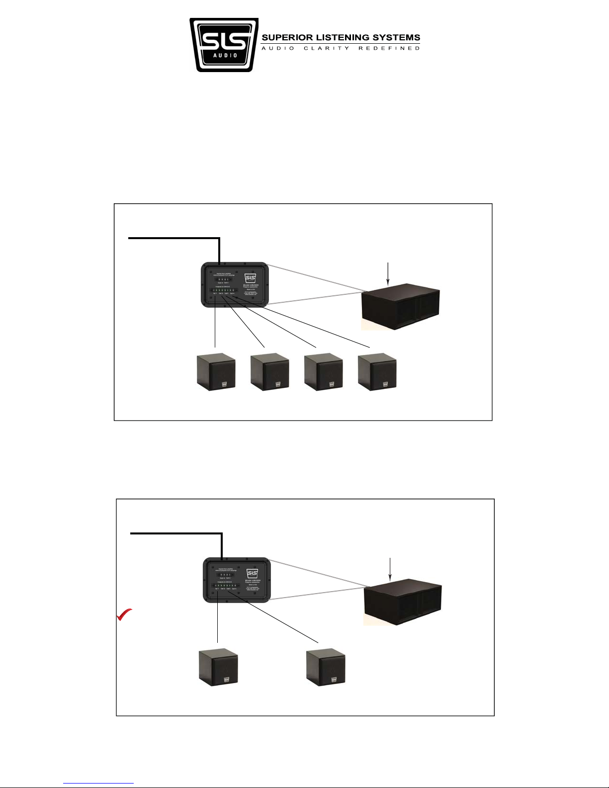
Congratulations on your purchase of the CM208W series subwoofers. ese subwoofers feature (2) long-
throw 8” drivers capable of response down to 35Hz with a peak SPL capability of 112dB per cabinet. ese
subwoofers also feature a flexible input and output feature set that allows use with all of our wall and ceiling
mount full range speakers. is Guide serves as an overview and provides useful hints regarding your
subwoofer installation and use. Please read in its entirety before proceeding.
Safety Responsibilities and Liability
All information in this guide is meant only for the purpose of rigging using the SLS supplied hardware. All
other rigging is considered part of the venue and/or end-user supplied equipment and is not addressed in
this guide. SLS assumes that a working knowledge of accepted rigging practices and safety will be applied to
all rigging materials and practices employed. is guide is not a comprehensive source for rigging in general.
e user must assume all responsibility for the appropriate use of SLS supplied rigging hardware and follow
at a minimum all applicable laws and regulations in force for each venue.
e weakest component determines the safety of the entire rigging assembly. Prior to installing, always
inspect all hardware components for wear, deformations, corrosion and missing or damaged parts. Also
inspect the venue attachment points for wear and confirm that the points are suitably load rated for the
equipment.
No information contained in this guide is intended as a warranty on the part of SLS. Anyone using this
information assumes all liability arising from it’s use. Product abuse, use of the product not in accordance
with SLS instructions or use in an application which the product has not been designed for is not covered
under any SLS warranty nor is SLS liable for any loss or damage.
Users in other countries should not assume that local regulations are based upon North American practices.
Users should consult with local regulatory authorities for specific codes and/or guidelines.
Replacement Parts
All defective components should be replaced with an SLS approved part. Contact the factory directly at
(417) 883-4549 to obtain approved replacement parts. SLS is not responsible for problems caused by using
non SLS supplied parts for the SLS supplied portion of the rigging.
Page 2 of 11

CM208W Series Wiring Schemes
e following diagrams show the different options available for incorporating the CM208W series subwoof-
ers into your installations. e diagrams show our CM141CC surface mount speaker connected to the
high-pass outputs but any 8 ohm speaker model can be used with the subwoofer. Best results will be
obtained by using SLS satellites however as the internal crossover in the CM208W series subwoofers are
optimized for SLS wall and ceiling speakers.
Stand Alone Subwoofer w/rigging points (CM208W shown)
or
Tile Bridge Subwoofer (CM208W-TB)
or
Sheetrock Subwoofer (CM208W-SR)
Speaker Level Full Range (8 ohm load, 400W Recommended)
Standard Configuration with Subwoofer & 4 Satellites
(4) 8 ohm Satellites
Stand Alone Subwoofer w/rigging points (CM208W shown)
or
Tile Bridge Subwoofer (CM208W-TB)
or
Sheetrock Subwoofer (CM208W-SR)
Speaker Level Full Range (8 ohm load, 400W Recommended)
Configuration with Subwoofer & 2 Satellites
(2) 8 ohm Satellites
Satellites must be
connected to either
outputs 1&3 or 2&4
Page 3 of 11

CM208W Series 70V Wiring Schemes
Stand Alone Subwoofer w/rigging points and optional transformer
or
Tile Bridge Subwoofer with optional transformer
or
Sheetrock Subwoofer with optional transformer
70V Output (60W Loading)
70V Configuration with Subwoofer & 4 Satellites
(with optional internal 70V transformer)
(4) 8 ohm Satellites
Stand Alone Subwoofer w/rigging points and optional transformer
or
Tile Bridge Subwoofer with optional transformer
or
Sheetrock Subwoofer with optional transformer
70V Output (60W Loading)
(2) 8 ohm Satellites
Satellites must be
connected to either
outputs 1&3 or 2&4
70V Configuration with Subwoofer & 2 Satellites
(with optional internal 70V transformer)
Page 4 of 11

CM208W Series Bi-amp Wiring Schemes
Stand Alone Subwoofer w/rigging points (CM208W shown)
or
Tile Bridge Subwoofer (CM208W-TB)
or
Sheetrock Subwoofer (CM208W-SR)
Speaker Level HF (4 ohm load)
Speaker Level LF (8 ohm load)
Bi-Amp Configuration with Subwoofer & 2 Satellites
(2) 8 ohm Satellites
A 12dB Butterworth LPF set at 100Hz and
a 24dB Butterworth HPF set at 100Hz is
recommended as a starting point.
Subwoofer should have a 12dB Butter-
worth HPF set at 24Hz.
Stand Alone Subwoofer w/rigging points (CM208W shown)
or
Tile Bridge Subwoofer (CM208W-TB)
or
Sheetrock Subwoofer (CM208W-SR)
Speaker Level HF (16 ohm load)
Speaker Level LF (8 ohm load)
Alternate Bi-Amp Configuration with Subwoofer & 2 Satellites
(2) 8 ohm Satellites
Remove lnput Jumpers
A symmetrical 24dB Butterworth crossover
set at 100Hz is recommended as a starting
point.
Subwoofer should have a 12dB Butter-
worth HPF set at 24Hz.
Satellites must be
connected to either
outputs 1&3 or 2&4
Page 5 of 11

Stand Alone Subwoofer w/rigging points (CM208W shown)
or
Tile Bridge Subwoofer (CM208W-TB)
or
Sheetrock Subwoofer (CM208W-SR)
Speaker Level HF (8 ohm load)
Speaker Level LF (8 ohm load)
Bi-Amp Configuration with Subwoofer & 4 Satellites
(4) 8 ohm Satellites
Remove lnput Jumpers
A symmetrical 24dB Butterworth crossover
set at 100Hz is recommended as a starting
point.
Subwoofer should have a 12dB Butter-
worth HPF set at 24Hz.
CM208W Series Bi-amp Wiring Schemes
Stand Alone Subwoofer w/rigging points (CM208W shown)
or
Tile Bridge Subwoofer (CM208W-TB)
or
Sheetrock Subwoofer (CM208W-SR)
Speaker Level HF (4 ohm load)
Speaker Level LF (8 ohm load)
Bi-Amp Configuration with Subwoofer & 8 Satellites
(8) 8 ohm Satellites
A symmetrical 24dB Butterworth crossover
set at 100Hz is recommended as a starting
point.
Subwoofer should have a 12dB Butter-
worth HPF set at 24Hz.
Remove lnput Jumpers
Page 6 of 11

CM208W Installation Guide
e CM208W variant is a standard installation type cabinet with (16) 3/8”-16 thread fly-point locations. It
can be used in a free standing design where the subwoofer is placed along a wall or corner or it can be flown
using the fly-points. Eyebolts are not included with this model but are readily available from local hardware
stores. Four suspension points are required for flying however two connection points to the structure can be
used by employing a bridle configuration. 1/8” wire rope is the minimum recommended sizing for the
rigging materials.
e CM208W can be flown either from the top as shown or from the back so that the woofers are facing
downwards. e performance differences will be small between the two options so the venue requirements
can dictate your flying configuration.
Page 7 of 11

CM208W-TB Installation Guide
e CM208W-TB variant is designed to be installed in 2’ x 2‘ tile bridge ceilings. You will need 18.5”
(47cm) of clearance above the tile grid for installation.
- e (4) eyebolts are included in the installation ring’s box. ese should be installed first.
- At this point the installation ring can be flown into position (without the subwoofer attached). It is never
recommended that the subwoofer be placed in the grid with no additional rigging to the supporting
structure. Position the ring so that the bottom surface facing the floor is about 2.5” (64mm) from the flat
side of the tile grid (the surface where the grill will rest on). is will later need to be lowered about 1.5”
(38mm). It is highly recommended that turn-buckles be used in the rigging for this purpose and also to
make fine adjustments to the force exerted on the grill by the weight of the subwoofer to prevent the grill
from rattling. A bridle may be used so that only two attachment point are needed to the structure. At this
time it is also a good idea to confirm that the grid is well supported by hanger wire all around the subwoofer
location. At a minimum, all four corners of the grid opening selected should have a hanger wire less then 5
inches away.
- Once the installation ring is in place, lift the subwoofer up through the 2’ x 2’ tile grid opening and the
installation ring. Make sure that the cut-aways on the subwoofer cabinet and the installation ring are
aligned. Push the subwoofer sideways to engage the installation ring in-between the bottom flange of the
subwoofer and the support piece (see below). A 2nd person can be used to hold the installation ring in place
while this is done. Push the subwoofer up into position using the support piece as leverage and fasten to the
installation ring with the (6) provided screws. e subwoofer should now be flown above the grid.
- Position the ladder underneath a grid opening next to the subwoofer. Take the grill up and slide it under-
neath the flown sub into the grid opening below. You should have about 1/4” clearance to do so.
- Using the turnbuckles or by loosening your rigging, lower the subwoofer approximately 1.5” (38mm) until
the rubber feet on the bottom of the cabinet just come into contact with the grill.
Support piece Included fasteners
Matched Cut-aways
Included eyebolts
Page 8 of 11

CM208W-SR Installation Guide
e CM208W-SR variant is designed to be installed in sheetrock ceilings. It ships with a pre-installation
ring and an external white grill. You will need 16” (40.6cm) of clearance above the bottom of the ceiling
joist for installation.
Included fasteners
Included grill fasteners
Pre-installation Ring
Grill
-e pre-installation ring must be installed so that the bottom is even with the bottom of the ceiling joists.
(is will make the subwoofer face flush with a 1/2” layer of ceiling material.) ere are no pre-drilled holes
in the ring for this mounting purpose so that you can have some flexibility. Typically, strips are installed on
the joists and wood screws are used that go through the installation ring into the strips that are vertically
positioned so that the installation ring is flush with the bottom side of the joist. Make sure that the T-nuts
on the pre-installation ring are facing upwards so that the subwoofer module can fasten correctly. After
this is done, a safety line can be installed from the structure and the wiring run. It is recommended that the
wiring hang down through the installation ring so that the location of the ring can be quickly located later.
Page 9 of 11

CM208W-SR Installation Guide (cont.)
- Once the sheetrock is finished, use a spiral saw (with a bit that contains a guide) to cut away the sheetrock
from the main center hole. After this, reset the bit and route out the sheetrock from the recess for attaching
the subwoofer.
- Align the subwoofer as shown with the cut-away on the installation ring. Lift the subwoofer through the
ring and rest it on the installation ring with the support piece fastened to the body of the subwoofer.
Support piece
Matched Cut-aways
- Lift up and fix the subwoofer to the installation ring using the six provided fasteners.
- Attach your cables to the input/output plate working through the provided access hole.
- Attach the grill with the (4) provided white screws.
Page 10 of 11

Specifications
Power Handling
Sensitivity (1W/1M - 1/2 Space)
Horizontal CoverageAngle -6dB
Product Specifications
35 - 200HzOperating Range 89dB
Omni
200W RMS
112dB SPL
400Watts @ 8 ohms
8 Ohms or optional 70V 60W tap
24Hz - 2nd order BW
Dual 8”
Barrier Strip
19” L
19” W
15.75” D
13ply Baltic Birch
45 lbs
Install/mounting ring
White Grill with white trim (paintable)
Max SPL (calculated) 1 Meter
RecommendedAmp Power for Max Output
Nominal Impedance
Suggested DSP Crossover Frequency - HPF
Transducers
Input/Output
Dimensions
Enclosure
Weight
Mounting
Finish
OmniVertical Coverage Angle -6dB
100Hz - 4th order BWLPF
OptionalAccessories Internal 60W 70V transformer
Power Handling
Sensitivity (1W/1M - 1/2 Space)
Horizontal CoverageAngle -6dB
Product Specifications
35 - 200HzOperating Range 89dB
Omni
200W RMS
112dB SPL
400Watts @ 8 ohms
8 Ohms, 70V 60W tap w/optional transformer
24Hz - 2nd order BW
Dual 8”
Barrier Strip
10.6” (27cm) H
24.6” (62.5cm) W
18.1” (46cm) D
13ply Baltic Birch
48 lbs (21.77kg)
(16) Threaded inserts for 3/8” -16 eyebolts
White
Black
Max SPL (calculated) 1 Meter
RecommendedAmp Power for Max Output
Nominal Impedance
Bi-amp Suggested xover Frequency - HPF
Transducers
Input/Output
Dimensions
Enclosure
Weight
Mounting
Finish Options
OmniVertical Coverage Angle -6dB
100Hz - 4th order BWLPF
OptionalAccessories Internal factory installed 60W 70V xformer
CM208W
CM208W-TB / CM208W-SR
Page 11 of 11
This manual suits for next models
2
Table of contents