CABASSE 30ND40 User manual

SANTORIN
notice d’installation des caissons de graves
subwoofers operating instructions
subwoofers gebrauchsanweisung
30
www.cabasse.com
Cab no ice San orin30B.qxd:Cab no ice Sub-03.qxd 11/05/09 15:26 Page1

TSA 500 P
A4 A5 A6 A7
A1 A2 A3
1
fr a n ç a i s - e n g l i s h - d e u t s c h
Cab no ice San orin30B.qxd:Cab no ice Sub-03.qxd 11/05/09 15:26 Page2

fr a n ç a i s - e n g l i s h - d e u t s c h
TP1 TP2
TP3
TP4
TP5
TP6
RC1
RC3
RC2
RC4
RC5 RC6
2
3
a
écran LCD - LCD display - LCD-Anzeige
Cab no ice San orin30B.qxd:Cab no ice Sub-03.qxd 11/05/09 15:26 Page3

f r a n ç a i s - e n g l i s h - d e u t s c h
4
5
6
Cab no ice San orin30B.qxd:Cab no ice Sub-03.qxd 11/05/09 15:26 Page4

en g l i s h
SAFETY INSTRUCTIONS
Explanation of graphical sym-
bols -
The lightning flash with
arrowhead symbol, within an
equilateral triangle, is inten-
ded to alert you to the presence of
uninsulated “dangerous voltage”
within the product’s enclosure that may be of sufficient magnitu-
de to constitute a risk of electric shock to persons.
The exclamation point within an equilateral triangle is intended
to alert you to the presence of important operating and
maintenance (servicing) instructions in the literature accom-
panying the appliance.
Instructions -
Carefully read through all the safety and oper-
ating instructions before switching on any device for the first
time.
Keep these instructions in mind -
They will be constant-
ly referred to through this manual.
Pay special care to warnings -
All the warning labels on the
product or warning notes in the user’s manual must be followed.
Follow the instructions -
ollow carefully all the installation
and operation instructions.
Cleaning -
Always remove the power cord before cleaning the
device. Do not use cleaning solvent, whether liquid or air spray.
Using a soft damp cloth is recommended.
Accessories -
To avoid incidents, only use accessories express-
ly recommended by Cabasse.
Water and moisture -
The product shall not be used in
damp or wet locations, such as humid basements, next to a bath-
tub, sink, swimming pool or any other similar conditions.
Carts and Stands - The appliance should be used
only with a cart or stand that is recommended by the
manufacturer.
> Portable cart warning
Installation on a piece of furniture and stands -
Do not
place this device on an unsteady surface, i.e. a stand, tripod,
table, shelf, etc. It may fall and cause serious injury to a nearby
child or adult.
Ventilation outlets -
The device shall not be placed in a posi-
tion that restrains the operation of its fans. Avoid installing the
device on a bed, couch, blanket or other similar surfaces that
may prevent the appropriate air flow. Do not install the device in
a confined space, such as a book shelf or other piece of furniture,
that could prevent sufficient air from flowing freely.
Power -
The device shall only be connected to a source of pow-
er compliant to the one described in this manual or on relevant
printed labels on the product. If you are not sure of the type of
power available, please contact your reseller or the local power
company.
Power cords -
The power cords must be laid out in such a way
that they cannot be walked on, pinched, bent under
other devices. Also pay special attention to the matching of the
plugs and the connection of the cord to the device.
Plastic bags -
Keep them away from children to prevent any
risk of suffocation.
Lightning -
or better protection against lightning or if the
device must remain unused for long stretches of time, unplug
the power cord and antenna jack. This minimises potential dam-
ages due to lightning or line surges.
Overloads -
Avoid overloading the power plugs, extension
cords or power relays. This could result in fire or electric shocks.
Foreign bodies and liquids -
Avoid letting foreign materi-
als or liquids enter the device. They could cause fire or electric
shocks. Never spill any liquid on the device.
Maintenance -
Users must never attempt to maintain the
device on their own, except for those maintenance operations
described in this manual. Any task beyond regular user mainte-
nance must be performed by qualified service operators.
Troubleshooting -
You must unplug your device from the
power supply and have it checked by a qualified technician if:
■The power supply or the plug is damaged.
■oreign bodies or liquid penetrated the device.
■The device was exposed to dripping or splashing.
■The device does not seem to work correctly under normal oper-
ating conditions. Only operate the controls described in this
manual. Any other operation could damage the device and require
on-site visit of a qualified technician.
■The device has fallen or its housing is damaged.
■The performances of the device are strongly altered.
Spare parts -
If spare parts are needed to repair the device,
make sure that the technician followed the manufacturer’s rec-
ommendations or that the replacing parts feature the same spec-
ifications as the original ones. Non-compliant parts can result in
multiple damages, including fire or electric shocks.
Checks -
After any servicing of the device, ask the technician to
perform appropriate testing to make sure that the device works
safely.
Exposure to high temperatures -
The device should be kept
away from heating sources, such as radiators, heaters, ampli-
fiers or any other similar item likely to make the operating tem-
perature rise excessively.
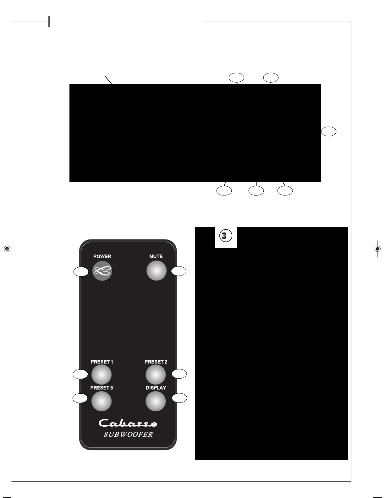
UNPACKING
The system is delivered in 2 cartons.
The larger packing includes one Santorin 30 subwoofer, a set of 4
decoupling cones, a power cable, the guarantee card and the owner's
manual.
The smaller packing contains a measurement microphone, a tabletop
microphone stand, a microphone amplifier with its power supply ,
2 XLR-XLR cables.
After opening the carton flaps of the main packing, fold them right
back and invert the carton contents.
After opening the top carton flaps, remove the grille. Then fold the car-
ton flaps right back and invert the carton contents.
Lift the carton clear of the contents and remove the inner packaging
from the speakers. We suggest you to retain the packing for future use.
hank you very much for choosing Cabasse speakers.
Please read these instructions carefully before setting up your speakers.
Caution ! o prevent electric shock, match wide blade plug to wide
slot, insert fully.
Applicable for USA, Canada or where approved for usage
Cab no ice San orin30B.qxd:Cab no ice Sub-03.qxd 11/05/09 15:26 Page10

e n g l i s h
POSITIONING
Speakers positioning
Our speakers have been designed to function in a vertical position.
The majority of our models are delivered with a set of decoupling
spikes or cones, these accessories are to be screwed in the inserts
under the cabinets. These accessories ensure the stability of the
speaker while limiting resonance coming from certain types of
grounds like wood floors.
Powerful drivers generate magnetic fields that can extend beyond
the boundaries of the speaker cabinet. We recommend you keep
magnetically sensitive articles (TV, computer screen, computer
discs, audio and video tapes, swipe cards...) at least 1.5 ft (50 cm)
away from the speaker. Cabasse centre speakers or the ones mar-
ked «TV» are not concerned with this, being magnetically shielded.
Positioning speakers in a room
Optimal positioning for a 2.1
or stereo with a subwoofer system
or a stereo listening with 2 speakers or 2 satellites and 1 sub-
woofer, we recommend you to place the subwoofer in the front lis-
tening area. The placement of the subwoofer against a wall reinforces
the low frequencies and limit the reflections from 80 to 200 Hz.
However to obtain the best results, it is always necessary to carry out
tests according to the acoustic of the room.
Optimal positioning for a 5.1
or home theatre system
Setting up a multi-channel Audio-Video system requires great care
when positioning the specific AV speakers.
■The centre speaker should be placed as close as possible to the
screen and where it sounds best from your listening spot while offe-
ring the optimal picture/dialogue cohesion. Theoretically, the screen
should be located within a virtual triangle formed by the acoustical
centres of the main speakers and the centre speaker. Practically
speaking, this means that the principal speaker should be placed abo-
ve the screen if the main speakers are below it, and below the screen
if the main speakers are above. The centre speaker should also, if pos-
sible, be set slightly back from the others, so that it is located at the
same distance from the listener as the main speakers.
■The rear speakers or surround should be placed against the side
walls, at listening height. They should not be positioned far behind
the listening zone.
■The subwoofer should be placed in the front listening area, its posi-
tion against a wall reinforces the extreme low register and limits
the reflections between 80 and 200 Hz. However to obtain the best
result, it is always necessary to carry out tests according to the
acoustics of the room.
Your AV processor enables the adjustment in level and delay of
each of the 5/6/7 channels of your system. ine-tuning is necessa-
ry to obtain a perfect sound stage.
Turn off all the amplifiers before connecting them to the loud-
speakers. In order to connect loudspeakers properly, it is most
important to keep in mind the following two factors: cable section
and phase.
CONNECTION
Cable section
To get the full sonic poten-
tial of Cabasse loudspea-
kers and avoid power
losses, the cables connec-
ting the speakers to the
power amplifier must have
the lowest possible electri-
cal resistance. To help you
in choosing the correct cable gauge, follow diagram.
Phase
In order to maintain the phase relationship and frequency balance of the
loudspeaker system, both loudspeakers must be properly connected to
the power amplifier. When properly connected, the cones of the drivers
of both loudspeakers will move in the same direction when driven by the
same signals. If the cones move in opposite directions, the resulting out
of phase signals will create a perceptible power loss, particularly in the
low frequencies. The stereophonic message will also be degraded. Ampli-
fier and speaker manufacturers typically indicate connection polarity
in one of two ways: red and black or plus and minus. In either case, always
connect red or plus to red or plus and black or minus to black or minus.
Connections should be identical for both channels. To check that the
speakers are in correct phase, switch the system to mono while music
is being played. if the amplifier does not have a phase inversion switch,
it will be necessary to change over the connections on one only of the loud-
speakers. If in correct phase, the image should be distinctly located bet-
ween the loudspeakers with a slight loss of bass and low midrange level.
If the image is confused and not centrally located and there is a drastic
loss of bass and low midrange level, recheck your connections.
Power management
Select the right voltage with the 115 V –
230 V switch and connect the
plug to the mains with a 700 W or more
power chord cable (3 A / 230 V, 6 A /
115 V). Then power on the amplifier
with the switch. inally press the
POWER key of the remote control or
any key on the front pad to get the sys-
tem on play mode. The display will be
activated after 3 to 4 seconds.
SETTINGS
I) THE AJUSTABLE PA AMETE S
USE O THE RONT PANEL PAD:
The 5 keys on the front panels of the Santorin 30 give access to all the
here-under adjustable parameters.
Use the “←“ and “ →“ (TP6 et TP3) keys to select the parameters,
then select the right option or value thanks to the “←“ et “→“ (TP6
et TP3) keys. The “ENTER” (TP1) key must be pressed down to confirm
a setting and/or answer to “ENTER ?” and “ VALIDATE ?”.
A3A1
A2
Attention,
before operating the unit,
be sure that the
operating voltage
of your unit is identical
with that of your local
power voltage.
Lenght between recommended
amplifier and loudspeakers section
4.5 m 1.5 mm2
6 m 2 mm2
7.5 m 2.5 mm2
9 m 3 mm2
12 m 4 mm2
Cab no ice San orin30B.qxd:Cab no ice Sub-03.qxd 11/05/09 15:26 Page11

e n g l i s h
A) PARA ETERS ADJUSTABLE ONLY BY EAN OF THE FRONT
PANEL :
- SOURCE : selection of the type of input/output being used :
■RCA+HL: RCA “LOW LEVEL INPUTS” inputs and
« HIGH LEVEL INPUTS » ( speaker cable terminals). These 2
types of inputs can be used simultaneously depending on
configuration.
■XLR : XLR inputs
- CHANNELS : selection of the input channels being used :
■R : right channel
■L : left channel
■R+L : right and left channels
- VOLUME : adjustment of the subwoofer sound level, -30 dB to +6
dB, pressing the “+” and “-“ keys in 1 dB increments.
- LOW PASS ILTER: adjustment of the subwoofer’s low-pass frequen-
cy, 30 Hz to 200 Hz, pressing the “+” and “-“ keys in 1 dB increments.
- PHASE: setting of phase of the subwoofer output signal, 0 to 180
degrees, pressing the “+” and “-“ keys in 1 dB increments.
- AUTO ACQUISITION: automatic setting of the subwoofer parametric
filters. It requires the use of the microphone and the microphone pream-
plifier delivered with the Santorin 30.
- PARAMETRIC 1 – PARAMETRIC 2 – PARAMETRIC 3: these 3 para-
metric modules allow the room adaptation of the subwoofer response
in order to decrease the acoustical defaults of the listening room in low
frequencies. They can either be activated manually or with the AUTO
ACQUISITION process.
The manual setting implies the adjustment of the following parameters
listed in the “PARAMETRIC 1 – PARAMETRIC 2 – PARAMETRIC 3 “sec-
tions:
■CENTER: it determines the middle frequency of the correction: it is
adjustable between 30 and 200 Hz in 1 dB increments.
■BAND WIDTH: width of the correction, from 1/8 of an octave up
to 2 (16/8) octaves in 1/8 of an octave increments.
■GAIN: intensity of the correction, adjustable from -12 dB to +4 dB
in 1 dB increments.
- POWER : Power management
■ON: the subwoofer is ready for activation either by pressing down
the “POWER” key on the remote control or by pressing down any key of
the front panel.
■O : the subwoofer is no longer activated. Activation requires to posi-
tion the POWER section on “ON” or “AUTO”
■AUTO: automatic power management with activation of the sub-
woofer when audio signal is received by the subwoofer. This is the set-
ting we advise to be used after the correct setup has been achieved. The
remote control can be stored until new setting becomes necessary.
- DELAY: compensation of the time delay when the subwoofer is placed
between the listening spot and the main speakers. It is adjustable bet-
ween 0 and 6.8 meters in 0.34 meter increments.
B) PARA ETERS ADJUSTABLE WITH THE FRONT PANNEL AND/OR
THE RE OTE CONTROL
- POWER : on and off switch of the subwoofer
- MUTE :
■MUTE ON : the sound signal is cut off, the subwoofer remains
powered and all the parameters can be adjusted.
■MUTE O : the subwoofer is on play mode
- PRESET 1, PRESET 2, PRESET 3: access to the end-user presets
- DISPLAY : Screen display : press this key to switch on or off the LCD dis-
play
EMOTE CONT OL KEYBOA D :
- POWER (RC1) : subwoofer’s power switch
- MUTE (RC2) :
■MUTE ON: the sound signal is cut off, the subwoofer remains
powered and all the parameters can be adjusted.
■MUTE O : the subwoofer is on play mode.
- PRESET 1, PRESET 2, PRESET 3 (RC4,RC5,RC6) : activation of the end-
user presets
- DISPLAY (RC7): Screen display : press this key to switch on or off the
LCD display
II) CONNECTIONS AND CONFIGU ATION :
The Santorin 30 has been designed for optimum results in almost eve-
ry audio and video application. These are the instructions for the main
domestic configurations:
2.1 CONFIGURATION : 2 satellites + 1 Santorin connected to a ste-
reo amplifier
Connect the right (R) and left (L) HI LEVEL inputs of the Santo-
rin to the loudspeakers’ output terminals of your amplifier with loud-
speaker cable. Be careful not to invert polarity and/or channels, the red
(+) terminals of the amplifier must be connected to the red (+) terminals
of the amplifier, and right amplifier’s output to the right inputs of the
subwoofer.
Connect the right (R) and left (L) HI LEVEL outputs of the San-
torin to the terminals of both satellite speakers. Respect polarities
and left and right when connecting the speaker cable between the
subwoofer and the satellites.
Connect the Santorin 30 to the mains and power it on.
Set the « SOURCE » and « CHANNELS » parameters as follow:
SOURCE = RCA + HL
CHANNELS = R+L
5.1 CONFIGURATION: 5 loudspeakers + 1 Santorin connected to an
AV-amplifier
Connect either the right(R) or the left (L) LOW LEVEL INPUT (A7) of
the subwoofer to the SUBWOO ER / L E output with an RCA/RCA
cable. If the amplifier or preamplifier is also fitted with a XLR output
for SUBWOO ER/L E we advise to choose it and connect it to one of
the (A6) BALANCED INPUTS of the Santorin 30.
Connect the Santorin 30 to the mains and power it on.
Set the « SOURCE » et « CHANNELS » parameters as follow :
■SOURCE = RCA + HL or XLR if BALANCED INPUT is being used
■CHANNELS = R or L
III) SANTO IN SET-UP P OCEDU E
Once the above connections have been fully done and the subwoofer
connected to the mains and switched on and activated with the
“POWER” of the remote control or any of the front keys, proceed to the
following set-ups using the front panel of the subwoofer.
A5
A4
A6
A7
A5
Attention ! he subwoofer might hum in such a configuration, depen-
ding on the ground specs of the other components. If so, the problem is
cancelled by joining the electrical grounds of the subwoofer and the
preamplifier with a RCA-RCA cable connected to one of the RCA inputs
of the subwoofer and to one available RCA input of the preamplifier.
Cab no ice San orin30B.qxd:Cab no ice Sub-03.qxd 11/05/09 15:26 Page12

e n g l i s h
A) SELECTION O THE SOURCE : check in « SOURCE » that the
inputs and outputs being listed are the ones being used:
■RCA+HL : RCA INPUTS and/or HI-LEVEL INPUTS/OUTPUTS
■XLR : XLR BALANCED INPUTS2)
B) INPUT CHANNEL SELECTION: check in « CHANNELS » the chan-
nel(s) being used :
a. R : Right channel
b. Left channel
c. R+L : both Left and Right channels
C) DELAY SET-UP: if the subwoofer is placed between the main spea-
kers and the listening spot or at a shorter distance to the listening spot
than the main speakers, the adjustment of the DELAY will improve the
sound result by entering in DELAY the difference between two distances.
The distance d1 is the radius of the circle passing by both main speakers
tweeters, the listening spot being its centre, d2 being the distance bet-
ween the sweet spot and the subwoofer ((4) scheme). The result r= d1-
d2 is the value to enter in the DELAY section if positive. If d2 is higher
than d1, then leave DELAY on “0” and go to the PHASE SECTION for
precise setting.
D) SELECTION O THE LOW PASS ILTER REQUENCY
The upper limit of the subwoofer’s frequency depends upon the type of
use of the subwoofer, the main speakers’ characteristics and the setting
possibilities offered by the AV-amplifier involved in the system:
5.1, 6.1, 7.1 set-up for single L E channel reproduction with full range
speakers for the other channels. The L E channel is monitored by the pro-
cessor of the AV amplifier, we therefore advise to set the low-pass filter
of the Santorin 30 on 200 Hz to avoid overlapping of both filters.
Multichannel set-up with satellites speakers requiring back-up of a sub-
woofer for reproduction of the bottom-end frequencies: adjust the low-
pass filter of the Santorin 30 on 200 Hz, then go in the SET-UP menu
of the AV amplifier, set the speakers sizes on SMALL when required
and set the cross-over frequency between subwoofer and satellites spea-
kers as close as possible to the characteristics of each satellite. Regarding
Cabasse speakers, select the frequency in the above table. If not listed
here, this frequency is available on the spec sheets of the products and
on www.cabasse.com
When the SET-UP menu allows only one cross-over frequency and
satellites with different roll-off frequencies are being used, then select the
highest frequency.
Stereo use with a stereo amplifier :
In this configuration the subwoofer and a pair of Cabasse satellites
speakers are connected to a stereo amplifier. Select the low pass frequency
in the above table and enter it into the set-up menu of the subwoofer.
An experienced installer will be able to select after measurements on site
other values than the ones we determined in our anechoic chamber,
taking into account the acoustical specifications of the listening room.
E) VOLUME ADJUSTMENT :when the set-up includes satellites spea-
kers, we recommend to first adjust the volume between the subwoo-
fer and the main speakers in stereo mode with a selection of music
rich in low frequencies. Once this set-up is achieved, adjust the L E level
in the set-up menu of the AV amplifier. urther L E levels adjustments
should be done in the AV amplifier and not in the subwoofer software.
) PHASE ADJUSTMENT: it allows if necessary to flatten the fre-
quency response around the cross-over point. If the subwoofer is clo-
ser to the listening point than the main speakers, then leave the PHA-
SE on the 0° and adjust the DELAY. The right setting is the one giving
the highest perceived level of low frequencies. Try first 0°, then 180°
and 90°. Other values should be used by experienced installers with
the help of measuring equipment. Readjust the phase each time you
move the subwoofer or the main speakers and each time you select a
new cross-over frequency.
G) PARAMETRIC ILTERS:
Thanks to our long experience in digital sound processing, we have
developed for the Santorin 30 unique room corrections modules. When
a graphic filter proposes volume adjustments on fixed bandwidth, our
parametric filters offer more precise and more natural settings, being per-
fectly focused on the critical zones. Sometimes the room acoustics
requires the use of only one parametric filter where a graphic filter will
in any case be active all along the bandwidth of the subwoofer and
create phasing shifts.
G1) AUTOMATIC ROOM EQUALISATION (5) (6)
1) Check that all the above settings are done and recorded.
2) Select « PRESET 2 » for the first adjustment in order to keep « PRE-
SET 1 » as a reference.
3) Unpack the measurements tools delivered with the subwoofer: micro-
phone, microphone-preamplifier, stand, power-supply, 2 cables
4) Place the microphone at the height of the listening point (P1 on dra-
wing (6)), connect it to the microphone-preamplifier “INPUT” with the
supplied XLR-XLR cable.
5) Connect the preamplifier to the Santorin by connecting its out-
put XLR « OUTPUT » to the input XLR « RIGHT » .
6) Set the « GAIN » and « OUTPUT » levels of the microphone’s
preamplifier at 12 o’clock and press down the 48V key. Power the
preamplifier by connecting the power supply to the 9 VAC input and
to a mains plug
7) In the subwoofer set-up :
a. Select « RCA+HL » as « SOURCE » in order to prevent any risk of
Larsen effect (whistling)
b. « CHANNELS »+ « VOLUME »: The software automatically selects
the right XLR input as the microphone input and runs the level control.
c. In «AUTO ACQUISITION », press enter to confirm the measurement
process.
d. « Start Acq. 1 ? » :
d1.Check that the microphone is right in the height of the listening
spot (P1).
d2. Press « ENTER » to launch the measurements acquisition 1
A5
A5
- ormentera : 80 Hz
- Minorca: 60 Hz
- aro: 50 Hz
- Riva: 45 Hz
- iO2 : 120 Hz
- Ki: 100 Hz
- Linea: 80 Hz
- Riga: 100 Hz
- Baltic Evolution : 80 Hz
Attention
if « no signal input » comes out on the LCD screen,
check all the connections and above setups and start
“AU O ACQUISI ION” again.
Cab no ice San orin30B.qxd:Cab no ice Sub-03.qxd 11/05/09 15:26 Page13
- ormentera : 80 Hz
- Minorca: 60 Hz
- aro: 50 Hz
- Riva: 45 Hz
- iO2 : 125 Hz
- Ki: 100 Hz
- Linea: 80 Hz
- Riga: 80 Hz
- Baltic Evolution : 65 Hz

e n g l i s h
e. « Start Acq. 2 ? » :
e1.Place the microphone around 1 m aside the (P1) position (left
or right, as for as possible from the walls), somehow in front of (P1)
and around 60 cm above initial position (P2)
e2.Press « ENTER » to launch the measurements acquisition 2
f. « Start Acq. 3 ? » :
f1.Place the microphone around 60 cm away from (P1) position,
opposite side of (P2) , somehow in front of (P2) and around 60
cm above initial position (P3)
f2.Press « ENTER » to launch the measurements acquisition 3
g. " inished!»: the automatic room compensation is achieved . Vali-
date the recording for the selected PRESET with “OK”. It is then pos-
sible to record other compensations in another PRESET with other
microphone positions.
Before starting listening tests: Select « XLR» as « SOURCE » if neces-
sary and unplug the microphone preamplifier from the subwoofer.
Check and if necessary set the “VOLUME” of the subwoofer, as the EQ-
process might have modified the sound level around the low-pass
frequency.
Unplug and store carefully the measurement equipment for eventual
further use after having completed the set-up of the subwoofer.
G2) MANUAL ROOM EQUALISATION
This way of setting up might bring better results than the Cabasse auto-
calibration system only if skilled people with specific measurement
equipment are involved. It can also be used to slightly modify some
auto-calibration values for audio comparisons of different PRESETS
((RC6) keys) or use of sources with different sound balances.
1) Select PRESET ( 1, 2 or 3)
2)Use the « » and « » keys (TP6 et TP3) of the control pad , then
« ENTER »to select one of the parametric modules : PARAMETRIC 1,
PARAMETRIC 2, PARAMETRIC 3.
3)« CENTER »: choose the middle frequency of the bandwidth to be
modified, between 30 and 200 Hz in 1 Hz increments.
4) « BAND »: select the width of the correction, , from 1/8 of an octa-
ve up to 2 (16/8) octaves in 1/8 of an octave increments.
5) GAIN: adjust intensity of the correction, adjustable from -12 dB to
+4 dB in 1 dB increments.
6) Validate the above 3 values : press the ENTER key (P1) on « EXIT ».
7) Proceed the same way for the other parametric modules if they are
to be used.
H) USE O PRESET1,PRESET2,PRESET3:
The factory setup is with PRESET 1 on. The gains of the 3 parametric
modules are set on 0 dB, bandwidth being on 1 Octave. The frequen-
cies are preset on 50 Hz for PARA 1, 60 Hz for PARA 2, 70 Hz for PARA
3.
1) Recording of a PRESET»: it is fully automatic, any new modifica-
tion of a parametric module is immediately recorded in the last selec-
ted PRESET.
2) Access to the PRESETS:
Direct access with the PRESET1, PRESET2, and PRESET 3 keys of the
remote control.
In the menu of the control pad: select « PRESET » with the « ←»
et « →» keys (TP6 et TP3) then PRESET1, PRESET2, or PRESET 3 with
the « ↓» et « ↑» keys (TP4 et TP2).
I) DISPLAY MODE
Press the « DISPLAY » key on the remote to control to get the display
“ON “ or “ O ”. The display mode can also be modified in the setup
menu using the keypad of the subwoofer.
SPECIFICATIONS &
TECHNICAL DATA
Santorin 30
Active subwoofer : 30 cm ø - model 30ND40
Frequency response : 22-200 Hz in semi-reverberating chamber
Maximum sound pressure level : 111 dB RMS
Maximum output power : 500 W RMS
Peak power : 1000 W
Lowpass cut-off frequency : 30 to 200 Hz in 1 Hz increments
Phase adjustment : 0° to 180° in 1° increments
Power requirements : 115 / 230 V AC - 50 / 60 Hz
Maximum power consumption : 625 W
Dimensions (h x w x d) : 43 x 36 x 68 cm - 16.9" x 14.2" x 26.8"
Weight : 28 kg - 62 lbs
Useable temperature range : +5°C to +35°C
Storage temperature : -5°C to +40°C
Useable humidity range : 40% to 70%
Because of technical improvements already under way in our constant
search for optimum quality, Cabasse reserves the right to modify all
the models presented in specification sheets, advertising materials
and manuals without prior notice.
Battery replacement: take the remote control in your hand with the key
side facing the floor. Press the locker and pull out the battery-tray
(picture 3a). Remove the dead battery and replace it with another 3V
lithium one, type CR2025. Dispose of the old battery according to
these instructions.
Disposal of battery packs / batteries
Do not dispose of battery pack/batteries into
house hold waste, fire or water. Battery
packs/batteries should be collected, recycled
or disposed of in an environmental friendly man-
ner.
Only for EC countries:
Defective or dead out battery packs/batteries must be recycled accor-
ding the guideline 91/157/EEC. or more detailed information about
recycling of this product, please contact your local city office, your hou-
sehold waste disposal service or the shop where you purchased the pro-
duct.
Cab no ice San orin30B.qxd:Cab no ice Sub-03.qxd 11/05/09 15:26 Page14

Cabasse SA - 210, rue René Descartes - BP 10 - 29280 Plouzané
Tel +33 (0)2 98 05 88 88 - Fax +33 (0)2 98 05 88 99
www.cabasse.com
NOT 0247
Cab no ice San orin30B.qxd:Cab no ice Sub-03.qxd 11/05/09 15:26 Page20
Other manuals for 30ND40
1
Table of contents
Other CABASSE Subwoofer manuals

CABASSE
CABASSE SANTORIN 21 User manual

CABASSE
CABASSE Furio User manual

CABASSE
CABASSE SANTORIN 30-200 User manual

CABASSE
CABASSE SANTORIN 30 I - User manual

CABASSE
CABASSE SANTORIN 21 User manual

CABASSE
CABASSE Santorin 30-500 User manual

CABASSE
CABASSE SANTORIN 30 I - User manual

CABASSE
CABASSE SANTORIN 30 I - User manual

CABASSE
CABASSE SANTORIN 30 I - User manual