Package contents
• One Supermicro Motherboard
• Four SATA Cables
• One I/O Shield
• One S-Connector
• One Quick Reference Guide
• One Driver CD
• Two Antennas (C9Z490-PGW only)
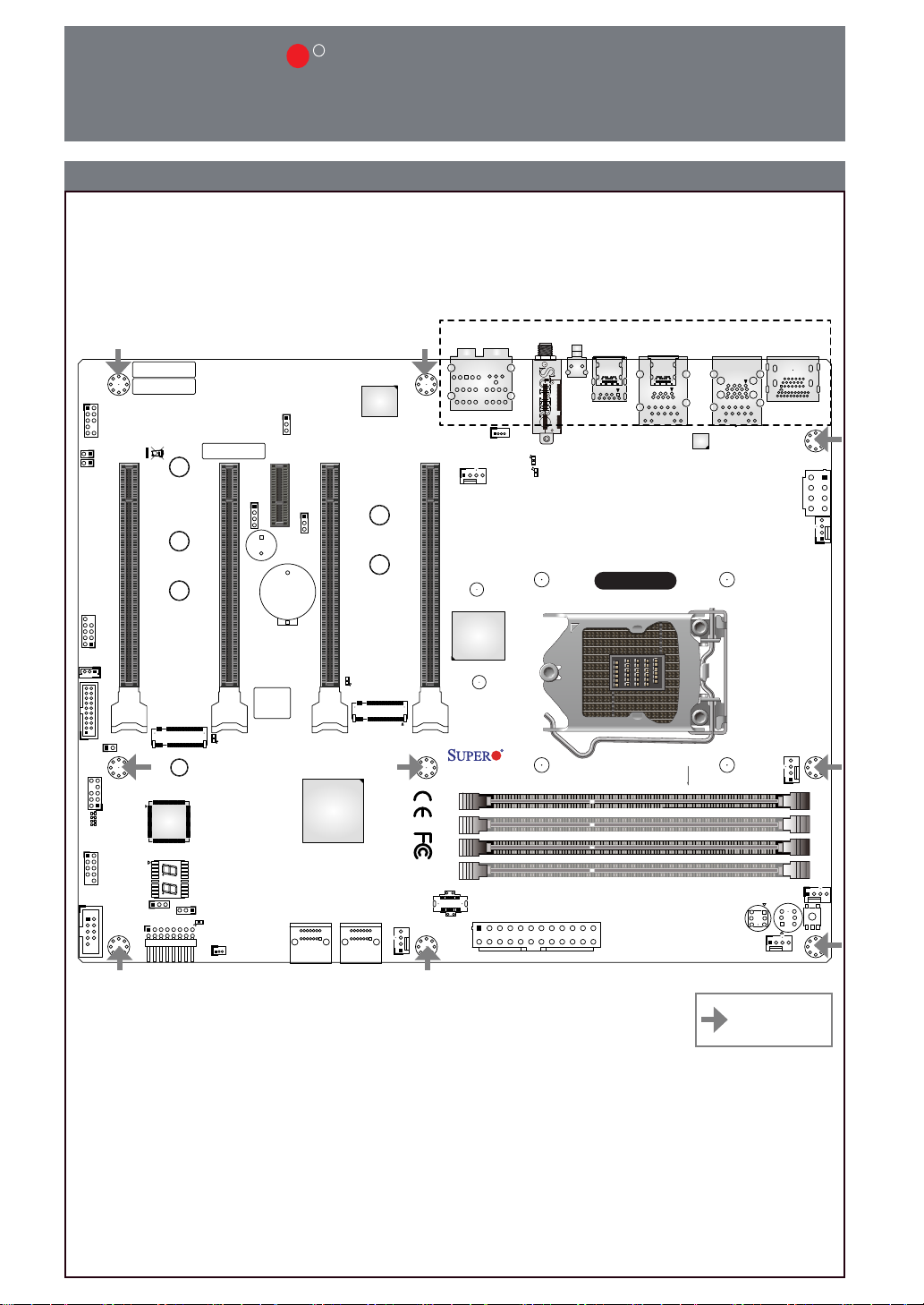
Connectors
Connector Description
12V_PUMP_PWR1 12V 4-pin Power Connector for CPU Liquid Cooling Pump
AUDIO FP Front Panel Audio Header
B1 Onboard Battery
COM1 COM1 Header
CPU_FAN1 ~ CPU_FAN2 CPU Fan Headers
CPU SLOT1/CPU SLOT5 PCI-E
3.0 x8 (IN x16)
PCIe 3.0 x16 Slots (PCIe 3.0 x8 Link )
*CPU Slot1/Slot5 PCIe 3.0 x8 (IN x16) slot shares PCIe x16 link with CPU Slot3/Slot7 PCIe 3.0 x16 slot,
therefore CPU Slot3/Slot7 PCIe 3.0 x16 link will change to PCIe 3.0 x8 link when one graphics card is
installed in CPU Slot1/Slot5 PCIe 3.0 x8 (IN x16) slot.
CPU SLOT3/CPU SLOT7 PCI-E
3.0 x16
PCIe 3.0 x16 Slots (PCIe 3.0 x16 Link)
*Always plug in one graphics card in CPU Slot3/Slot7 PCIe 3.0 x16 slot rst to maximize performance.
DP/HDMI Back Panel DisplayPort/High Denition Multimedia Interface
HD AUDIO High Denition Audio Ports
I-SATA0~3 (Intel Z490) Serial ATA (SATA 3.0) Ports 0~3 (6Gb/sec)
JD1 Speaker/Buzzer (Pins 1~4: External Speaker, Pins 3~4: Buzzer)
JF1 Front Control Panel Header
*Please align the printed indications on the S-Connector with the corresponding pins on JF1 when plugging in.
JL1 Chassis Intrusion Header
JLED1 Power LED Indicator Header
JPW1 24-pin ATX Main Power Connector (Required)
JPW2 +12V 8-pin CPU Power Connector (Required)
JRLED1 4-pin Connector for a White Light LED Board (Pre-installed) Inside the I/O cover
JSD1 SATA DOM (Disk-On-Module) Power Connector
JSTBY1 Standby Power Header
JTPM1 Trusted Platform Module (TPM)/Port 80 Header (Supports TPM 2.0 only)
LAN1/LAN2 RJ45 10GbE/5GbE LAN Ports
PCIE M.2-E1 WiFi 6+BT 5.1 (Pre-installed, for C9Z490-PGW only)
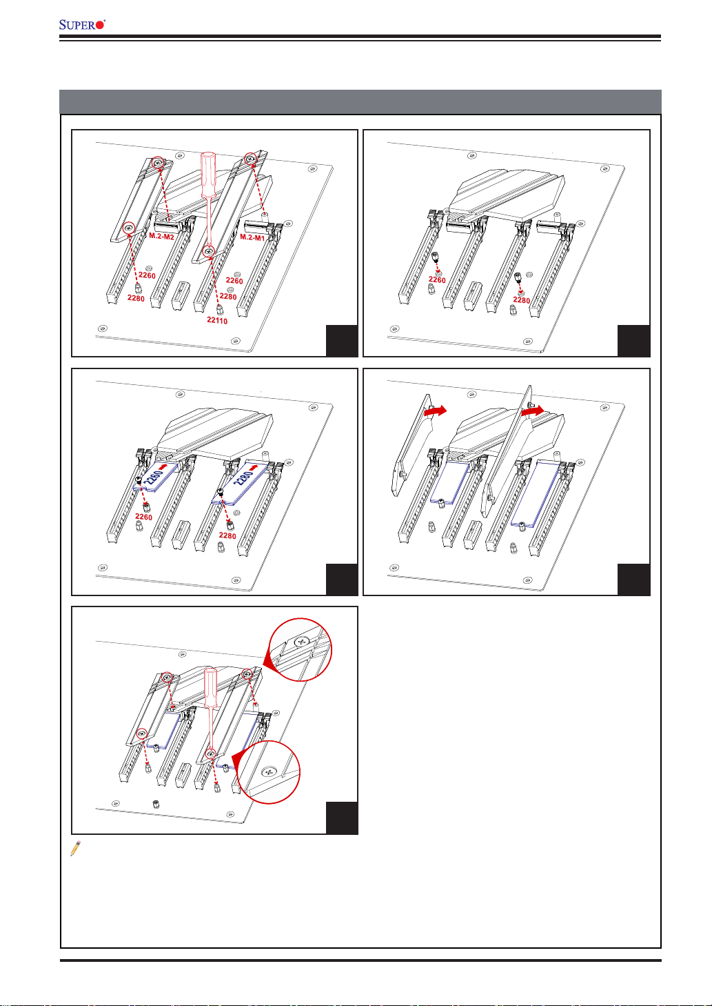
PCIE M.2-M1/M.2-M2
PCIe M.2 M Key Sockets. Small Form Factor Devices and Other Portable Devices for High
Speed NVMe SSDs
*Support RAID 0,1.
PCH SLOT4 PCI-E 3.0 x1 PCIe 3.0 x1 Slot (PCIe 3.0 x1 Link)
SP1 Internal Speaker/Buzzer
SYS_FAN1 ~ SYS_FAN3 System Fan Headers
USB 0/1, 2/3 Front Panel Accessible USB 2.0 Headers
USB 4/5 Back Panel USB 3.2 Gen 1 Ports (Type A)
USB 6 Back Panel USB 3.2 Gen 2 Port (Type A)
USB 7 Back Panel USB 3.2 Gen 2 Port (Type C)
USB 8 Back Panel USB 3.2 Gen 2 Port (Type A)
USB 9 Back Panel USB 3.2 Gen 2x2 Port (Type C)
USB 10/11 Front Panel Accessible USB 3.2 Gen 1 Header
USB 12 Front Panel Accessible USB 3.2 Gen 2 20-pin Connector
Jumpers and Connectors
Jumpers
Jumper Description Default
CLEAR CMOS Clear CMOS Switch Push Button Switch
JI2C1/JI2C2 SMB to PCIe Slots Open (Off): Disable
JPAC1 Audio Enable/Disable Pins 1-2 (Enable)
JPME2 Intel Manufacturing Mode Pins 1-2 (Normal)
JWD1 Watch Dog Function Enable Pins 1-2 (RST)
POWER BUTTON Internal Power Button Push Button Switch
RESET BUTTON Onboard System Reset Button Push Button Switch
SW1 Back Panel Clear CMOS Switch Push Button Switch