Sur-Gard MLR2E User manual

Installation and
Operation Manual
version 1.4
WARNING: This manual contains information on limitations regarding
product use and function and information on the limitations as to
liability of the manufacturer. The entire manual should be carefully read.
Sur-Gard MLR2E
Multi-Line Digital Receiver

Table of Contents
Section 1 - Introduction .................................................. 1
1.1 CPM2 ................................................................. 1
1.2 DRL2E ................................................................ 1
1.3 Supervision ......................................................... 1
1.4 CPM2 Outputs/Inputs ......................................... 1
1.5 System Overview ................................................ 1
1.6 Virtual Receiver Architecture ................................ 2
1.7 Number of Line Cards Supproted ........................ 2
1.8 Approvals ........................................................... 2
Section 2 - Quick Start ................................................... 6
2.1 Receiver Setup and Operation without
Programming ...................................................... 6
Section 3 - Installation .................................................. 7
3.1 Mounting the Receiver ........................................ 7
3.2 Printer Connections ............................................ 7
3.3 Computer Connections ....................................... 7
3.4 Telephone Line Connections ............................... 7
3.5 Grounding .......................................................... 7
3.6 Power Supply ..................................................... 7
3.7 Battery Charging Current ..................................... 7
Section 4 - DRL2E Digital Receiver Line Card ................ 8
4.1 General information ............................................ 8
4.2 DRL2E Features ................................................... 8
4.3 DRL2E Controls .................................................. 8
Section 5 - DRL2E Operating Mode ................................. 9
5.1 DRL2E Standby Mode ......................................... 9
5.2 DRL2E Cold Boot............................................... 10
5.3 Communications in Progress ............................. 11
Section 6 - Profiles ...................................................... 12
6.1 Introduction ..................................................... 12
6.2 DRL2E Programming Commands ...................... 13
6.3 Static Options: [00] - [2F] ................................. 14
6.4 Dynamic Options: [30] - [FF] ........................... 16
Section 7 - DRL2E Communication Formats ................. 23
7.1 Common Formats .............................................. 23
7.2 Sur-Gard DTMF Formats .................................... 23
7.3 Ademco Contact ID ........................................... 23
7.4 Ademco Express ............................................... 23
7.5 Scantronics ....................................................... 23
7.6 Ademco Super Fast (High Speed Format) ........... 23
7.7 DMP FSK ........................................................... 23
7.8 FBI Super Fast Format ........................................ 24
7.9 ITI Format ......................................................... 24
7.10 Modem II, Modem IIE, Modem IIIa² and
BFSK Formats 25
7.11 SIA FSK ............................................................. 25
7.12 Silent Knight FSK1, FSK2 .................................... 26
7.13 Silent Knight FSK2 Protocol ................................ 26
7.14 SESCOA SUPER SPEED ...................................... 27
7.15 DRL2E Predefined Library Decoding and
Event Codes Table ............................................. 27
Section 8 - CPM2 Central Processing Module ............... 28
8.1 General Information .......................................... 28
8.2 Feature .............................................................. 28
8.3 CPM2 Controls ................................................. 28
8.4 CPM2 Operating Mode ..................................... 29
8.5 Message Priorities ............................................. 34
8.6 CPM2 Utility Modes .......................................... 35
8.7 CPM2 EPROM Programming .............................37
Section 9 - Automation Protocols ................................ 38
9.1 Data Byte protocol ............................................ 38
9.2 Acknowledgment of the Signal ........................... 38
Appendix A - DRL2E Communication Formats .............. 39
Appendix B - ASCII Character Chart ............................. 40
Appendix C - Decimal - HEX - Binary Conversion Chart 41
Appendix D - Printer Words: Options [60-6F] ............... 42
Appendix E - Default Static Options ............................. 44
Appendix F - Default Dynamic Options [30] - [AF] ....... 45
Appendix G - Event Code Classifications ...................... 46
FCC Compliance Statement
CAUTION: Changes or modifications not expressly approved by Digital Security Controls Ltd. could void
your authority to use this equipment.
This equipment has been tested and found to comply with the limits for a Class B digital device, pursuant
to Part 15 of the FCC Rules. These limits are designed to provide reasonable protection against harmful
interference in a residential installation. This equipment generates, uses and can radiate radio frequency
energy and, if not installed and used in accordance with the instructions, may cause harmful interference to
radio communications. However, there is no guarantee that interference will not occur in a particular
installation. If this equipment does cause harmful interference to radio or television reception, which can
be determined by turning the equipment off and on, the user is encouraged to try to correct the interference
by one or more of the following measures:
Re-orient the receiving antenna.
Increase the separation between the equipment and receiver.
Connect the equipment into an outlet on a circuit different from that to which the receiver is connected.
Consult the dealer or an experienced radio/television technician for help.
The user may find the following booklet prepared by the FCC useful: “How to Identify and Resolve
Radio/Television Interference Problems”. This booklet is available from the U.S. Government Printing
Office, Washington D.C. 20402, Stock # 004-000-00345-4.
IMPORTANT INFORMATION
This equipment complies with Part 68 of the FCC Rules. On the side of this equipment is a label that con-
tains, among other information, the FCC registration number and ringer equivalence number (REN) for
this equipment. If requested, this number must be provided to the Telephone Company.
FCC Registration Number: 1VDCAN-35164-AL-N
REN: 0.1A
USOC Jack: RJ11C
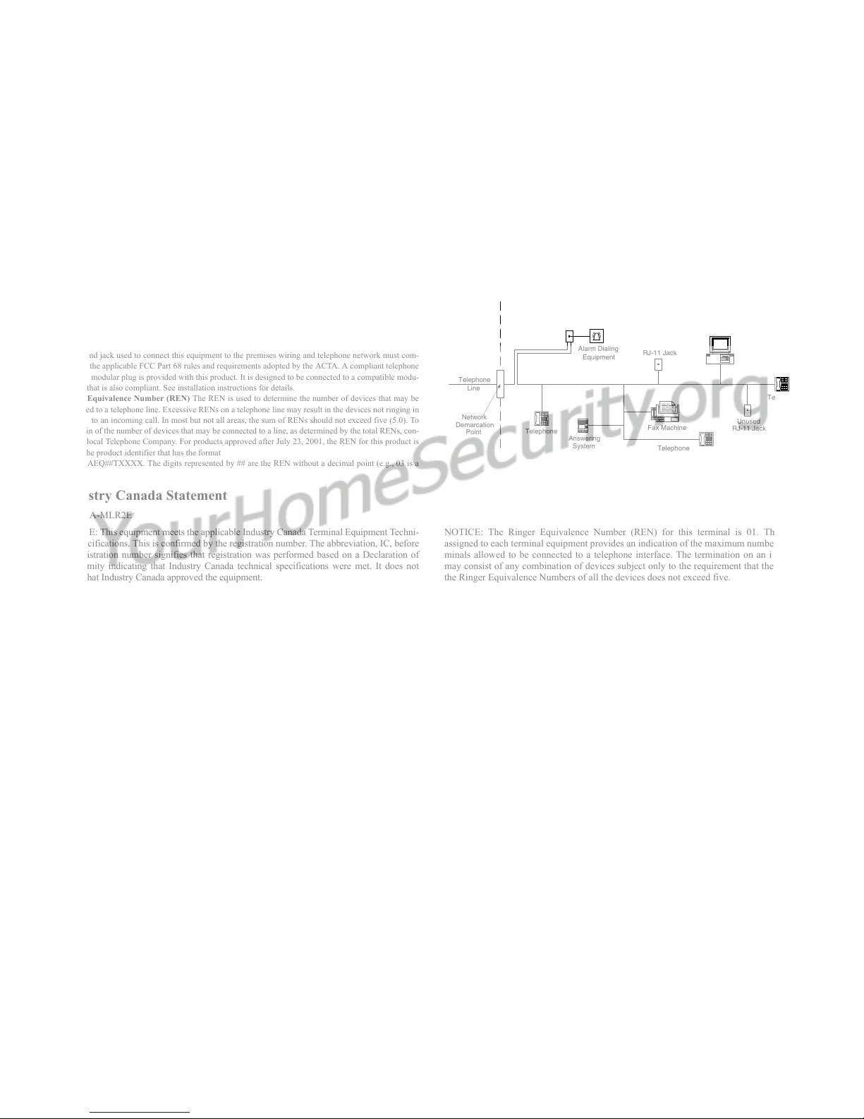
Telephone Connection Requirements
A plug and jack used to connect this equipment to the premises wiring and telephone network must com-
ply with the applicable FCC Part 68 rules and requirements adopted by the ACTA. A compliant telephone
cord and modular plug is provided with this product. It is designed to be connected to a compatible modu-
lar jack that is also compliant. See installation instructions for details.
Ringer Equivalence Number (REN) The REN is used to determine the number of devices that may be
connected to a telephone line. Excessive RENs on a telephone line may result in the devices not ringing in
response to an incoming call. In most but not all areas, the sum of RENs should not exceed five (5.0). To
be certain of the number of devices that may be connected to a line, as determined by the total RENs, con-
tact the local Telephone Company. For products approved after July 23, 2001, the REN for this product is
part of the product identifier that has the format
US: AAAEQ##TXXXX. The digits represented by ## are the REN without a decimal point (e.g., 03 is a
REN of 0.3). For earlier products, the REN is separately shown on the label.
Incidence of Harm If this equipment Sur-Gard MLR2E causes harm to the telephone network, the tele-
phone company will notify you in advance that temporary discontinuance of service may be required. But
if advance notice is not practical, the Telephone Company will notify the customer as soon as possible.
Also, you will be advised of your right to file a complaint with the FCC if you believe it is necessary.
Changes in Telephone Company Equipment or Facilities The Telephone Company may make changes
in its facilities, equipment, operations or procedures that could affect the operation of the equipment. If
this happens the Telephone Company will provide advance notice in order for you to make necessary mod-
ifications to maintain uninterrupted service.
Equipment Maintenance Facility If trouble is experienced with this equipment Sur-Gard MLR2E, for
repair or warranty information, please contact the facility indicated below. If the equipment is causing
harm to the telephone network, the Telephone Company may request that you disconnect the equipment
until the problem is solved. This equipment is of a type that is not intended to be repaired by the end user.
Simplex Time Recorder Co. 100 Simplex Drive, Westminster MA 01441-0001 USA, Tel: (978) 731-2500
Additional Information Connection to party line service is subject to state tariffs. Contact the state public
utility commission, public service commission or corporation commission for information.
If your home has specially wired alarm equipment connected to the telephone line, ensure the installation
of this equipment Sur-Gard MLR2E does not disable your alarm equipment. If you have questions about
what will disable alarm equipment, consult your telephone company or a qualified installer.
Industry Canada Statement
IC: 160A-MLR2E
NOTICE: This equipment meets the applicable Industry Canada Terminal Equipment Techni-
cal Specifications. This is confirmed by the registration number. The abbreviation, IC, before
the registration number signifies that registration was performed based on a Declaration of
Conformity indicating that Industry Canada technical specifications were met. It does not
imply that Industry Canada approved the equipment.
NOTICE: The Ringer Equivalence Number (REN) for this terminal is 01. The REN
assigned to each terminal equipment provides an indication of the maximum number of ter-
minals allowed to be connected to a telephone interface. The termination on an interface
may consist of any combination of devices subject only to the requirement that the sum of
the Ringer Equivalence Numbers of all the devices does not exceed five.
Telephone
Computer
Telephone
Telephone
Fax Machine
Alarm Dialing
Equipment
RJ-31X
Jack Unused
RJ-11 Jack
Telephone
Line
Network
Service
Provider's
Facilities
Customer Premises Equipment and Wiring
Unused
RJ-11 Jack
Network
Demarcation
Point Answering
System

1
Section 1 - Introduction
The MLR2E is a multi-line, multi-format digital receiver for
commercial fire and burglary. The basic unit consists of up
to 15 individual line card modules (DRL2E) and 30 telco
lines connected to a CPM2. The MLR2E can decode a vari-
ety of popular and widely used communication formats.
Refer to Appendix A, DRL2E Communication Formats for a
list of the available communication protocols.
The MLR2E’s real-time clock and calendar stamps all infor-
mation received with the time and date, and all information
can be printed and/or forwarded to a computer. To ensure
security, adjustment of the clock, calendar and other pro-
gramming is password-protected.
1.1 CPM2
The CPM2 Central Processing Module oversees oper-
ation of the line cards. Along with its built-in keypad
and LCD message screen, the CPM2 features one par-
allel printer port, and two COM Ports.
1.2 DRL2E
Each DRL2E module can monitor two telephone lines.
The line card module is equipped with a 256-event
non-volatile memory buffer to record events and cor-
responding telephone numbers. Caller Source capabil-
ity is built-in and telephone numbers can be printed
out, sent to automation and stored in memory. Events
and information stored in memory can be printed at
any time. Each line card also features flash EPROM
uploads through the Debug port for software
upgrades or options programming.
1.3 Supervision
The standby battery voltage and connections are
supervised. The line cards are also continuously
supervised to ensure uninterrupted communication
with the CPM2. Any trouble conditions are reported
on the LCD screens and sent to the printer and the
computer.
The DRL2E line card module also verifies communica-
tions with the CPM2. In the event of a malfunction,
the operator will be advised with a visual indication
and the line cards will continue to function. Each line
card will continue to receive information.
The printer is supervised for loss of power, off-line,
paper out and other trouble conditions. The commu-
nication link to the computer through the RS-232 port
is monitored by the supervisory “heartbeat” test
transmissions.
1.3.1 Compatibility
Central station automation software packages such as
M.A.S., DICE, SIMSII, S.I.S., GENESIS and MICROKEY
support the MLR2E Sur-Gard interface. Compatibility
with the automation software in a system used at a
central station is intended to be handled under a sep-
arate UL 1981 software package and/or site certifica-
tion evaluation.
1.4 CPM2 Outputs/Inputs
The CPM2 features three switched-negative outputs.
One output labeled “OPTION” has a corresponding
LED on the CPM2 front panel; the factory default pro-
gramming slowly flashes the OPTION LED when the
“OPTION” output is activated. Switched negative out-
puts are also provided for the Acknowledge and Trou-
ble LEDs.
1.5 System Overview
• Patented Caller Identification (Call Display) capability
• Patent pending DNIS identification
• Battery backed up RAM on each DRL2E line card
module for programming and event buffers.
• Fast communication between line cards and CPM2
• Flash upload for software upgrades
• Up to 64 different options set (profiles per line)
• Patented Virtual configurations
• 4/2 formats with or without parity, 4/1, 3/1 without
parity at 10, 14, 20, or 40 Baud
• 4/1, 4/2, 4/3, and 4/3 with checksum DTMF for-
mats
• Optional* formats: 3-2, 4/2 extended, 3/1 parity
• Contact ID (DTMF) format
•Super Fast or High Speed DTMF format, with or
without parity
• DTMF 4/1 Express format optional*, 4/2 Express
format
• FBI Super Fast format with or without parity
• RADIONICS Modem II, Modem IIE, Modem IIIa2
and BFSK formats
• SIA format: 110 and 300 Baud, tone and data
acknowledgment
• SK FSK1, FSK2
• Any handshake frequencies by increment of 100
Hz from 300 Hz to 3400 HZ, Dual Tone, SIA FSK,
Modem IIx, Double Dual Tone and ITI selected by
configuration commands.
• Up to 8 different handshakes per profile with indi-
vidual duration control.
• Large, easy to read 2-line, 16-characters-per-line,
Liquid Crystal Display screen
• All modules function individually to help ensure
uninterrupted operation during hardware or soft-
ware upgrades
• Inputs on CPM2 for UPS supervisory
• 30 lines maximum per receiver
• 256-event memory buffer on each individual line
card
• Real-time clock
• CPM2 features 16-bit microcontroller
• 1 parallel printer port and 2 serial RS-232 ports
• Programmable serial port configurations
• Programmable system functions: computer and
printer
• Fast transmission of multiple alarms to the com-
puter and printer to ensure operator’s quick
response
• Continuous verification of the computer-receiver
links with the “heartbeat” function
*All formats noted as optional are selected using configuration commands.

2
• Switched-negative outputs on CPM2 (special appli-
cations)
• AC-lost detection and standby battery supervision
• Low battery detection and automatic low battery
disconnect to prevent deep-discharge damage to
battery
• Operator Acknowledge option
• Telephone line supervision and reporting
1.6 Virtual Receiver Architecture
The most novel feature of the DRL2E is its ability to
use the telephone company information delivered as
DNIS (Dialed Number Information Service) or Caller
ID. This allows the Sur-Gard Format Expert System to
handle on the fly each received call. With this feature,
dedicated line pool hardware is eliminated. Instead,
the DNIS or Caller ID information allows dynamic
options that set up virtual line pools to identify secu-
rity formats and extend account numbers.
Standard DNIS is supported up to 10 digits. Each
dialed number should be assigned to a virtual receiver.
Multiple Caller ID numbers can be assigned to a single
virtual receiver. Each dialed number would formerly
have been a line pool on conventional line cards.
1.7 Number of Line Cards Supported
The system will support a maximum of 15 line card
modules concurrently connected.
1.8 Approvals
1.8.1 Agency Listings
• UL 864 Control Units for Fire-Protective Signaling
Systems
• UL 1610 Central Station Burglar Alarm Units
This equipment should be installed in accordance with
the requirements of NFPA72, NFPA70, UL827 and the
local authority having jurisdiction.
1.8.2 UL Manual Mode
For UL manual mode, each event will activate the
internal buzzer to be acknowledged manually. Each
event will also be sent automatically to the connected
printer.
For Central Station applications, the signaling perfor-
mance of each DACT (Digital Alarm Communication
Transmitter) shall be manually tracked. Failure to
receive a signal from a DACT over a 24 hour period
shall be handled as a trouble signal.

3
Figure 1, MLR2E Backplane Connection
Figure 2, Connection for DML2E Line Card Expansion
P
6
MV3 MV2
P
5
P4 P2
R13
R11
R4
R6
R7
R12
Battery
12V Rechargeable
lead-acid
35Ah
Transformer
16 VAC, 175 VA
For 120VAC Mains For Model
SG-MLR2E CE*
120VAC
60Hz
* Model MLR2E CE is not UL approved.
4
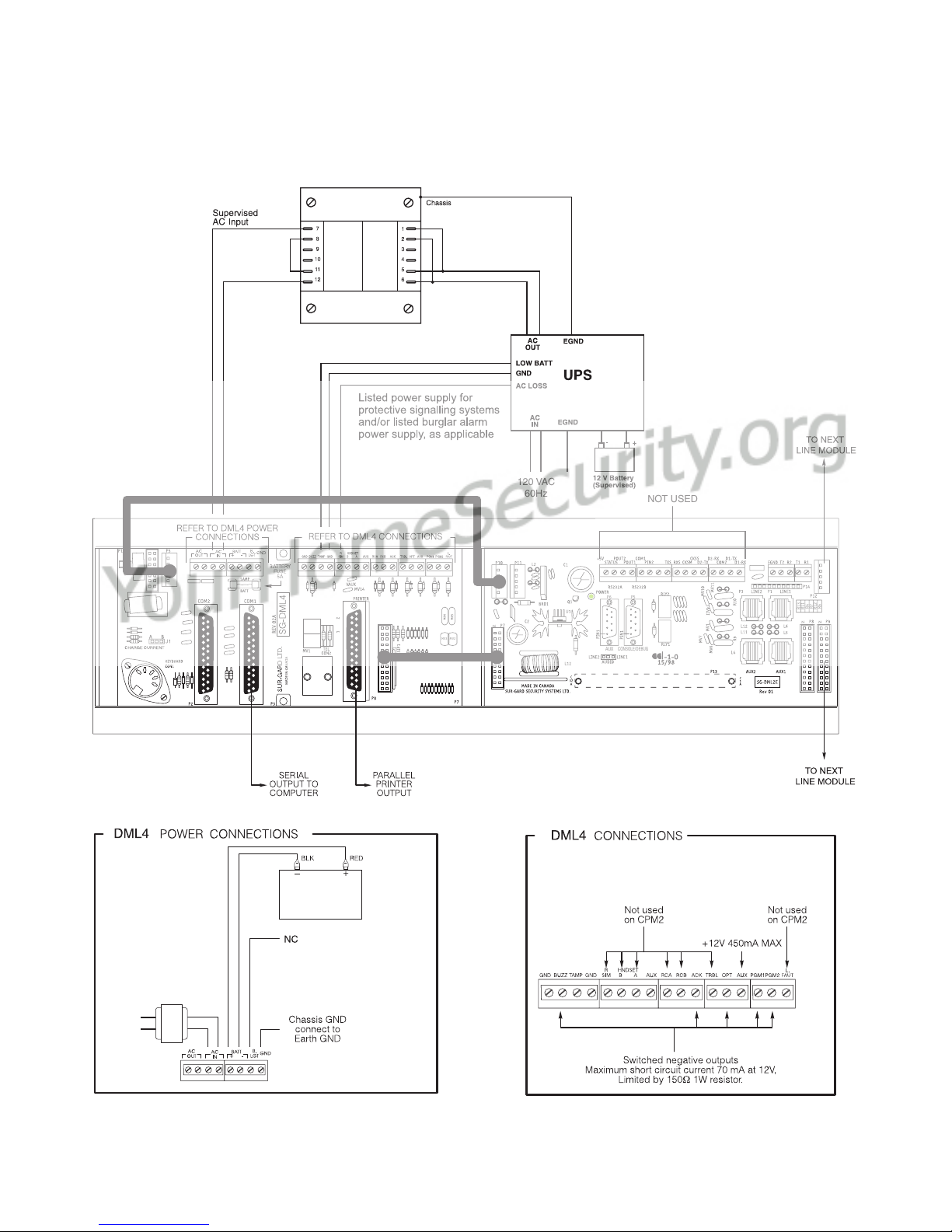
Figure 3, MLR2E UL UPS Connection, 120 VAC Mains
P
6
MV3 MV2
P
5
P4 P2
R13
R11
R4
R6
R7
R12
Battery
12V Rechargeable
lead-acid
35Ah
120 VAC
60Hz
120 VAC
60Hz
Transformer
16 V , 175 VA
AC
120 V /16 V , 60 Hz, 175 VAAC AC
TRANSFORMER
NOT USED
AUX
CONSOLE/DEBUG

5
Figure 4, Model MLR2E CE UPS Connection, 240 VAC Mains*
* Not to be used in UL Listed Installations. Use only with Model SG-MLR2E CE (not UL Listed).
P
6
MV3 MV2
P
5
P4 P2
R13
R11
R4
R6
R7
R12
240 V /16 V , 50 Hz, 175 VAAC AC
TRANSFORMER
240 VAC
50 HZ
12 V Battery
upervised(S )
NOT USED
AUX
CONSOLE/DEBUG
Battery
12V Rechargeable
240 V
50 Hz
AC
lead-acid
35Ah
Transformer
16 V , 175 VA
AC
GROUND CONNECTION
Tighten nut to break paint
and make a good connection
to the cabinet
Ground
wire from
building
electrical
installation
Nut
Star washer
Lock washer
Lock washer
Nut
Cabinet
Bolt
6
Section 2 - Quick Start
2.1 Receiver Setup and Operation without
Programming
2.1.1 Unpacking
Carefully unpack the receiver and inspect for shipping
damage. If there is any apparent damage, notify the
carrier immediately.
2.1.2 Bench Testing
It is suggested that the receiver be tested before
actual installation; becoming familiar with the connec-
tions and setup of the unit on the workbench will
make final installation more straightforward.
The following items are required:
•16V
AC, 175VA transformer
•2telephonelines
• One or more dialers or digital dialer control panels
Dialers and control panels using an optocoupler
phone line interface will require a connection method
providing a DC current for direct connection testing.
2.1.3 Power Up
When power is applied, the receiver will beep and will
indicate any trouble conditions on the LCD message
screen. If the line cards do not have telephone lines
connected, the DRL2E modules will beep and their
“Line Fault” LEDs will FLASH.
Press the flashing [ACK] button to silence the buzzer.
If there is no computer or printer connected, a trouble
message will be displayed on the CPM2 LCD and the
“ACK” light will FLASH. Press the [ACK] button to
silence the CPM2 buzzer.
2.1.4 Operation with Default Programming
Without any changes to the factory default program-
ming, the receiver operates as follows:
• Answers incoming calls on the first ring
• Sends SIA FSK as the first handshake
• Sends 1400 Hz as the second handshake
• Sends double dual tone as the third handshake
• Sends 2300 HZ tone as the fourth handshake
• Sends Modem II tone as the fifth handshake
• Sends ITI, Modem IIE, Modem IIIa2 tone as sixth
handshake
• The following formats can be manually selected: 3/
2, 4/1 express, 4/2 extended, 4/2 checksum and 3/
1 checksum.
Signals can be displayed on the debug output as they
are received. The signals are then sent to the parallel
printer and computer connected to serial port COM1.
The default event codes described in the “DRL2E
Library Decoding and Event Codes Table” will be used
with the Sur-Gard Automation Communication Proto-
col to send signals to the computer, if connected.
If a computer is not connected, press the [ACK] but-
ton on the CPM2 module to silence the buzzer.
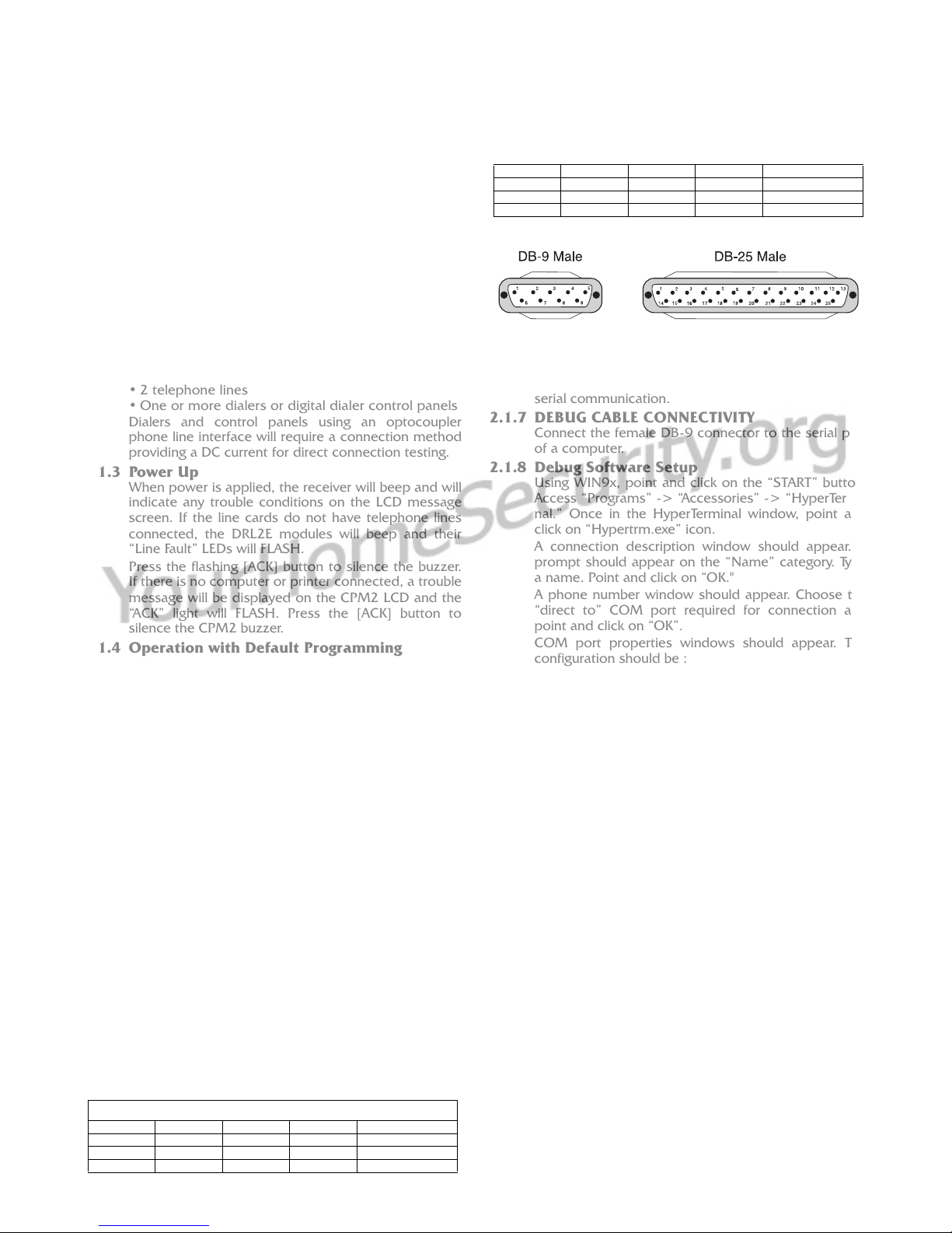
2.1.5 Serial Laplink Cable for Debug/Console
For Debug/Console data transfer between a PC and
the DRL2E, a serial data transfer cable is used to con-
nect either the DB9 male or DB25 male serial ports on
a computer to the DB9 male serial (Debug/Console)
port on the DRL2E.
Figure 5, Seral Laplink Cable (on cable)
2.1.6 DEBUG OUPUT
The debug output is another means of accessing the
line card’s programmed options and diagnostics fea-
tures. A null modem cable is required to connect by
serial communication.
2.1.7 DEBUG CABLE CONNECTIVITY
Connect the female DB-9 connector to the serial port
of a computer.
2.1.8 Debug Software Setup
Using WIN9x, point and click on the “START” button.
Access “Programs” -> “Accessories” -> “HyperTermi-
nal.” Once in the HyperTerminal window, point and
click on “Hypertrm.exe” icon.
A connection description window should appear. A
prompt should appear on the “Name” category. Type
a name. Point and click on “OK."
A phone number window should appear. Choose the
“direct to” COM port required for connection and
point and click on “OK”.
COM port properties windows should appear. The
configuration should be :
• Bits per second: 19200
• Data bits: 8
•Parity:None
•Stopbits:1
•Flowcontrol:None
Point and click on the “OK” button after setting the
configuration.
The HyperTerminal window should appear. Press any
button. The debug menu will be displayed.
2.1.9 Button commands
CCold boot
DThis button will initiate the download of a file to the
line card.
OThis button will enable the user to dump the cur-
rent programmed options of the line card or set
an option to a particular value.
VTo view software version information
2.1.10Downloading steps
Press the “D” button to initiate downloading of the
binary file. The HyperTerminal will display:
Ready to download.
CCCC
Point and click at “Transfer” on the HyperTerminal
menu and access the “Send File” category (you also
have right-click access with the mouse). The “Send
File” window should appear. Change the protocol to
“X-modem” and place the correct path and file name
of the binary file to be uploaded. Point and click on
the “Send” button and the downloading status win-
dow should appear.
The line card will restart automatically after a success-
ful upload.
Serial Laplink Cable
from DB9 from DB25 to DB9 to DB25 Signal
2323Receive-Transmit
3232Transmit-Receive
4 20 6 6 DTR - DSR
5775Ground - Ground
6 6 20 4 DSR - DTR
7458RTS-CTS
8547CTS-RTS

7
Section 3 - Installation
3.1 Mounting the Receiver
Install the MLR2E in a closed 19" / 48cm rack or cabi-
net with a locking rear access door. Cover all unused
spaces with blank metal plates. The LCD screens on
the receiver are designed to be viewed below eye
level. If the unit must be mounted where the screens
are above eye level, angle the unit downwards to
improve visibility. The following items can be supplied
for a complete installation:
3.1.1 Stand-up Unit (61.25" / 1.55cm tall up to 30
telephone lines)
Part # MLR2-CL
•Rack
• Door with lock and ventilation
• Blank plates 21" / 53cm (2)
• Blank plate 5.25" / 13.3cm (3)
•Screws
• Washers
• Clipnuts
• FROST 16V/175VA transformer
P/N FT3304
• AC utility box
• AC cable clamps (2)
• 8' / 2.4m battery cables
• 3-Gauge conductor AC cable
• Secondary non-replaceable fuse, 15A, 125 VAC
NOTE: If 30 telephone lines are not used, cover
each unused location with a blank plate.
3.1.2 Desk-mount Unit (28" / 71cm tall up to 14
telephone lines)
Part # MLR2-CM
•Rack
• Louvered door back plate
• Blank Plate 1.75" / 4.45cm
• Back Plate 7" / 17.8cm
• Blank Plates 5.25 (4)
•Screws
• Washers
• Clipnuts
• FROST 16V/175VA
• AC utility box
• AC cable clamp for 3/8" / 1cm cable
• 8' / 2.4m battery cable
• 18 gauge 3-conductor AC cable
• Secondary non-replaceable fuse, 15A, 125 VAC
NOTE: If 18 telephone lines are not used, cover
each unused location with a blank plate.
3.2 Printer Connections
Connect the parallel printer to the MLR2E printer out-
put port using a standard parallel printer cable.
For UL Listed applications, the following UL Listed
printers can be used with the MLR2E:
• Sur-Gard CPU-1150
• Sur-Gard CPU DMP-206
•DMPSCS-PTR
IMPORTANT: Do not use a printer cable that has
only 1 common ground wire.
3.3 Computer Connections
Connect the computer to the MLR2E RS-232 port
using a serial cable to COM1. IMPORTANT: Do not
use a null modem cable.
Figure 6, MLR2E COM1/COM2 Automation Computer Con-
nection
3.4 Telephone Line Connections
With 6-pin modular cables, connect each line module
jack (line 1 or 2) to its corresponding telephone line.
3.5 Grounding
For maximum resistance to static and electrical noise,
the 19"/48cm rack frame should be connected to
earth ground through the AC utility box.
3.6 Power Supply
Ensure that all electrical connections are made cor-
rectly. After verifying all connections, connect the RED
and BLACK leads to a 12VDC sealed rechargeable bat-
tery. Be sure to observe polarity when connecting the
battery. When the battery is connected, test the sys-
tem under battery power only. CAUTION: Connect-
ing a positive (+) terminal to a negative (-) terminal
may cause a fire and possibly serious personal
harm.
For 4-hour standby a 12-volt 35 Ah rechargeable bat-
tery should be used in conjunction with an engine-
driven power generator.
3.7 Battery Charging Current
The maximum battery charging current is factory set at
1A.
Receiver RS-232
25-pin connector
Computer RS-232
25-pin connector
Receiver RS-232
9-pin connector
111
223
332
775
8
Section 4 - DRL2E Digital Receiver Line Card
The DRL2E acts as an interface between the digital alarm
transmitter and the CPM2. Different communication for-
mats can be used to transmit the information.
The main functions of the line cards are to continuously
monitor the telephone line, receive calls from digital dialers
or control panels, and to report alarms to the CPM2. In
addition, each line is capable of functioning independently
when communication is lost between the line card and the
CPM2. Each line card can record 256 different alarm mes-
sages and 255 Caller-ID telephone numbers.
4.1 General information
The receiver is capable of processing signals from dig-
ital communicators in a variety of formats. The type of
signal (alarm, trouble, restore, cancel and so on) can
be printed.
4.2 DRL2E Features
• Operator selection of communication formats and
handshake priority
• 64 profiles per line, up to 30 lines.
• Flash Download for software upgrades.
• Records up to 256 messages.
• Records up to 256 Caller ID phone numbers. This
feature helps to locate and identify the source of
the device in communication and assists in trouble-
shooting.
• Multiple alarms are forwarded to the computer and
printer through the CPM2 with minimum delay
• The DRL2E monitors the telephone line connec-
tion, and line faults will result in reports to the
computer and the printer
• DRL2E automatically goes into standalone mode in
case of CPM2 failure
• “Watchdog” timer continually monitors receiver
operation
• “Cold boot” option allows receiver’s configuration
to be reset to factory default programming
• DSP processing to reduce data receiving errors,
and to help for weak and noisy signals
• Gain boost available to amplify weak signals
• Serial link for troubleshooting and easy software
upgrade
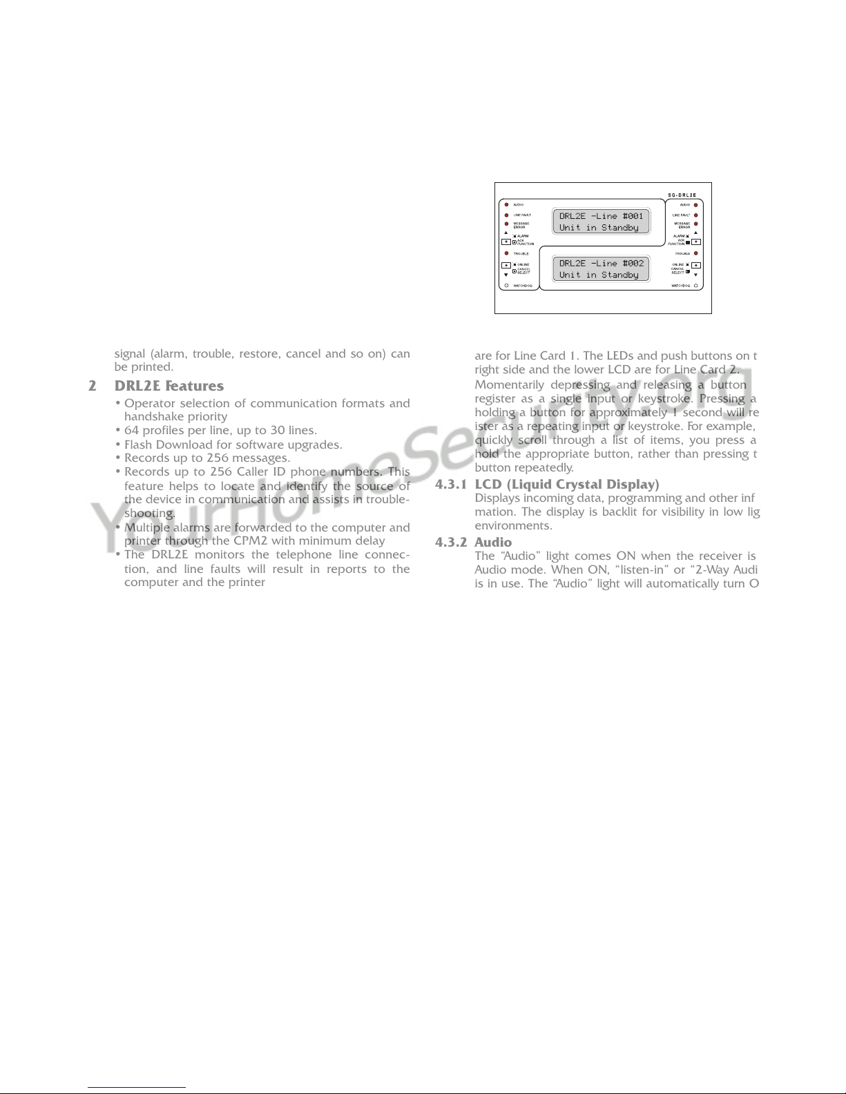
4.3 DRL2E Controls
Figure 7, DRL2E Faceplate
Each DRL2E Module features 2 line cards. The LEDs
and push buttons on the left side and the upper LCD
are for Line Card 1. The LEDs and push buttons on the
right side and the lower LCD are for Line Card 2.
Momentarily depressing and releasing a button will
register as a single input or keystroke. Pressing and
holding a button for approximately 1 second will reg-
ister as a repeating input or keystroke. For example, to
quickly scroll through a list of items, you press and
hold the appropriate button, rather than pressing the
button repeatedly.
4.3.1 LCD (Liquid Crystal Display)
Displays incoming data, programming and other infor-
mation. The display is backlit for visibility in low light
environments.
4.3.2 Audio
The “Audio” light comes ON when the receiver is in
Audio mode. When ON, “listen-in” or “2-Way Audio”
is in use. The “Audio” light will automatically turn OFF
at the end of the timed period or when the [CANCEL]
button is pressed.
4.3.3 Line Fault
The “Line Fault” light will come ON if the telephone
line is disconnected. The “Line Fault” light will turn OFF
automatically when the telephone line is restored.
4.3.4 Message Error
The “Message Error” light will come ON when faulty
data is received (for example, if the round pair does
not match, or if the checksum is incorrect). Press the
[ACK] button to acknowledge the error; the “Message
Error” light will be shut OFF.
4.3.5 [ACK/FUNCTION] Button
Press this button to acknowledge an alarm in emer-
gency manual mode. In the normal mode, press this
button to access the line card menu.
4.3.6 Alarm
The “Alarm” light is located inside the [ACK/FUNC-
TION] button. The “Alarm” light will flash if an alarm is
received. The “Alarm” light will be shut OFF when the
alarm is successfully communicated to the CPM2, or
when the operator acknowledges the alarm by press-
ing the [ACK/FUNCTION] button.
4.3.7 Cancel Select
While on-line, press this button to drop the line. In nor-
mal mode, press this button to select the current item.
4.3.8 Watchdog
The "Watchdog" light will FLASH once every 4 seconds
to indicate that line card operation is being monitored.

9
Section 5 - DRL2E Operating Mode
5.1 DRL2E Standby Mode
When the line card is operating normally, this message
will be displayed:
DRL2E–Line #D
Unit in Standby
5.1.1 Line Fault
The DRL2E verifies the telephone line voltage every 10
seconds. The “Line Fault” light will come ON after two
successive line verifications indicate irregular tele-
phone line voltage. This message will be displayed:
DRL2E-Line #D
<<-Line Fault->>
If the Line Check option is enabled, the following
information will be transmitted to the printer and
computer:
Printer:L01-0000-PHONE-LINE-TROUBLETIME:DATE
(printer option set to 03)
Computer: 0RRL[#0000 | NLTRRL]
NOTE: The first RRL is subject to the line card
length option. The second RRL is the receiver and
line card number, both in HEX.
If the Line Check option is disabled, the DRL2E will
not send the report to the printer or computer. Refer
to “DRL2E Programmable Features” for information on
enabling the Line Check option.
When the line condition returns to normal, the “Line
Fault” LED will be shut OFF.
If the Line Check option is enabled and the telephone
line returns to normal, the following information will
be transmitted to the printer and computer:
Printer:L01-0000-PHONE-LINE-RESTORALTIME:DATE
Computer: 0RRL[#0000 | NLRRL]
NOTE: The first RRL is subject to the line card
length option. The second RRLL is the receiver and
line card number, both in HEX.
5.1.2 CPM2 Error; Display Alarm Messages
If the DRL2E cannot detect CPM2 polling and there
are no alarm events in the event buffer, this message
will be displayed:
DRL2E–Line #D
<<-CPM ERROR->>
If alarm messages cannot be sent to the CPM2
because of the error, the DRL2E will display the oldest
message which has not been manually acknowledged.
The “Alarm” light will FLASH and the sounder will beep
if the “Mute Buzzer” option is programmed as [00],
[02] or [03].
When a CPM2 error is present, each alarm must be
manually acknowledged. Press the [ACK/FUNCTION]
button to acknowledge the alarm and silence the line
card sounder. If several alarms have been received but
cannot be sent to the CPM2, they will have to be indi-
vidually acknowledged; when all alarms are acknowl-
edged, the line card sounder will be silenced.
Up to 128 alarm messages for the printer and com-
puter will be retained in the CPM2 event buffer. When
the event buffer is full, the oldest messages will be
deleted as new events are recorded.
When the CPM2 error condition is corrected, the
alarm messages in the event buffer will be transmitted
to the CPM2.
5.1.3 Keep Last Alarm Message
The DRL2E may be programmed to leave the last
alarm message on the display screen until a new mes-
sage is received. A typical alarm message is shown
below:
0000–PHONE LINE
TROUBLE 28
“0000” is the “internal” account code.
“28” is the event’s location in the event buffer.
5.1.4 Line Card Menu Mode
When the unit is not on line, pressing the [ACK/FUNC-
TION] button will display the first function menu:
PRINTER BUFFER
ACK:menu SEL:sel
Press the [ACK] button to scroll through the menu
items. Press the [SELECT] button to select the func-
tion displayed on the LCD screen. When a function is
selected, press [ACK] and [SELECT] together to exit
from the Menu mode. The DRL2E will automatically
exit from the Menu mode if no keys are pressed for
30 seconds.
The following functions are available in the line card
Menu mode:
• Display Printer Alarm Buffer
• Display Line Card Configuration
• Display Program Version
• Adjust LCD Contrast
•AdjustBacklight
5.1.5 Display Printer and Caller ID Alarm Buffer
PRINTER BUFFER
ACK:menu SEL:sel
With this message displayed, press the [SELECT] but-
ton; the most recent alarm message will be displayed.
If Option [12] CALLER SOURCE is selected, the corre-
sponding Caller Identification will also be displayed.
Press the [SELECT] button to scroll backwards through
alarm messages; press the [ACK] button to scroll for-
ward through alarm messages.
Press the [ACK] button to display the alarm message:
3576-312
Alarm 001
“3576” is the Account Code.
In this example, a 4/3 communication format is used.
“3” indicates an alarm, while “12” is the zone number.
“Alarm” indicates an alarm.
“001” is the event’s location in the event buffer.
The event buffer can record up to 256 alarm mes-
sages and Caller Identifications. To print these mes-
sages, a print command can be sent from the CPM2;
refer to “CPM2 Utility Mode” for information.

10
If no Caller Identification data was received from the
telephone company, the following message will be
displayed when the [ACK] button is pressed to display
the Caller Identification screen:
1234 — UnknownCall
If the Caller Identification is sent but with no tele-
phone number, one of these messages could be dis-
played:
1234 — PRIVATE NO
1234 — UNAVAILABLE
If Option [12] is disabled, the Caller Identification fea-
ture will be bypassed; only the alarm messages will be
displayed. Press [ACK] and [SELECT] together to
return to the Standby mode. If no keys are pressed,
the DRL2E will automatically return to the Standby
mode after 30 seconds.
5.1.6 Display Options
DISPLAY OPTIONS
ACK:menu SEL:sel
With this message displayed, press the [SELECT] but-
ton; the current Option Configuration will be dis-
played. Shown below is the first screen you will see,
representing profile 0. Use the ACK button to scroll
through all 64 profiles (0-63).
Select Profile 0
Ack: up SEL: sel
Press [ACK] and [SELECT] together to return to the
Standby mode.
options display
and description
5.1.7 Display Program Version
PROGRAM VERSION
ACK:menu SEL:sel
With this message displayed, press the [SELECT] but-
ton; the date and the software version number will be
displayed as shown below:
SG -DRL2E V1.4
Sep 02,2002
Press [ACK] and [SELECT] together to return to the
Standby mode.
5.1.8 Adjust LCD Contrast
Adjust CONTRAST
ACK:menu SEL:sel
With this message displayed, press the [SELECT] but-
ton to adjust the LCD screen’s contrast. When the
[SELECT] button is pressed, this message will be dis-
played:
Adjust CONTRAST
....
Press the [ACK] button to increase the contrast; press
the [SELECT] button to reduce the contrast. The dis-
play will indicate the contrast level on the second line.
Press [ACK] and [SELECT] together to return to the
Standby mode.
5.1.9 Adjust Backlight
ADJUST BACKLIGHT
ACK: up SEL: down
The [ACK] button is used to brighten the backlighting
and the [SELECT] button is used to darken it.
5.2 DRL2E Cold Boot
There are two methods of cold booting a DRL2E line
card:
5.2.1 Using the Line Card
1. Remove all four screws from the linecard.
2. Remove the line card out of the rack.
3. Replace the line card back into the rack. As you
slide the line card back in you hold the [ACK] and
[SELECT] buttons in.
4. It will then prompt you to do a cold boot. You
press the [ACK] button for yes, or the [SELECT]
button for no.
COLD BOOT?
ACK: yes SEL: no
5. Once you have pressed the [ACK] button it will
start the cold boot process on the first line.
COLD BOOTING
Channel X
6. After it has finished cold booting it will prompt you
to “Change LC Number.”
7. You select [ACK] for yes, and [SELECT] for no.
CHANGE LC NUMBER?
ACK: yes SEL: no
LINECARDNUMBER:0E
ACK: up SEL:down
8. Once you have assigned the line card a number
you press and hold the [ACK] and [SELECT] but-
tons for two seconds. This exits the cold boot pro-
cedure.
INITIALIZING
CONTRAST LOADING
During this time, the line cards will load default
options and code, and perform a low-level diagnostic
to determine the status of the system.
Once the line cards are ready, they will display a mes-
sage similar to the following:
DRL2E-Line #D
<<-Line Fault->>
9. Repeat the process for the second line.
10.After the second line has been completed tighten
the four screws.
5.2.2 Using the Debug
From HyperTerminal, press “C” to perform a cold boot
and select which channel to cold boot, either 1 or 2.
The following will appear on the display:
COLD BOOT
Which Channel?-Hit 1 or 2
Channel X
X = 1 or 2
Cold Booting

11
5.3 Communications in Progress
5.3.1 Data Reception
During data reception, a message similar to this will
be displayed:
In Communication
1234 56
If valid Caller Identification information is received, a
message similar to this will be displayed:
TEL:15145551212
1234 56
The DRL2E decodes all information received and
stores the information in its event buffer. When a valid
signal is received, the DRL2E sends a kissoff signal
and transmits the decoded alarm signal to the com-
puter and then to the printer through the CPM2.
Options [1D] and [1E] can be adjusted to allow the
DRL2E to compensate for weak signals or noisy tele-
phone lines; refer to “DRL2E Programmable Features”
for information on programming these options.
The DRL2E will send each message it receives to the
printer for review by the system operator. Two mes-
sages may be sent to the printer to indicate reception
problems: “Invalid Report” and “Communication Fail”.
5.3.2 Invalid Report Message
When this problem is encountered, the following
information is transmitted to the printer and the com-
puter:
Printer: L01- 0000-INVALID REPORT TIME:DATE
Computer: 0RRL[#0000 | NYNRRL]
NOTE: The first RRL is subject to the line card
length option.The second RRL is the receiver and
line card number, both in HEX.
This output for account code “0000” indicates that
data has been received, but is not valid (for example,
there are unmatched rounds or the wrong parity). The
following is an example of faulty data received by the
DRL2E, and the printer output generated:
NOTE: There is only 1 invalid report at the end of a
call.
5.3.3 Communication Fail
When this problem is encountered, the following
information is transmitted to the printer and the com-
puter:
Printer: L01-0000-COMMUNICATION FAIL TIME:
DATE
Computer: 0RRL[#0000 | NYCRRL]
NOTE: The first RRL is subject to the line card
length option. The second RRLL is the receiver and
line card number, both in HEX.
This output indicates that a call was received, but no
data was detected. The call may have been a wrong
number, or the calling control panel was unable to
connect with the receiver’s handshake.
5.3.4 Caller ID
If an Invalid Report or Communication Fail occurs,
and Caller ID is enabled, the printer messages will be
similar to the following:
Fault Data: “??????10 5551212”
Fault Call: “??????40 5551212”
Note that “?” represents the missing data; “5551212”
represents the originating telephone number.
5.3.5 Stopping Data Reception Manually
To cancel communications between the DRL2E line
card and the calling control panel, press the [CANCEL]
button. Pressing the [CANCEL] button will hang up the
line. This feature can be used to hang up on a control
panel that is repeatedly sending alarms.
Round Data Received Printer Output
1st 123456 [No printout]
2nd 123446 ?1234?56 Invalid
Report
3rd 123356 ?1234?46 Invalid
Report
4th 123456 ?1233?56 Invalid
Report
5th 123356 ?1234?56 Invalid
Report
?????10 Invalid Report
12
Section 6 - Profiles
6.1 Introduction
The DRL2E 'virtual receiver' will load unique 'profiles' in
order to effectively communicate with control panels.
A profile is a set of pre-programmed line card options
unique for a particular DNIS number. The 'DNIS' will
point to a particular profile, which will then be loaded
into the line card before the first handshake is sent. It
is essential that the correct option be programmed for
a profile in order to correctly communicate with the
control panel. Each 'virtual receiver' can have a maxi-
mum of 64 profiles. To change the options for a par-
ticular profile, the MLR2E Console software is
provided. This software will allow the user/operator to
edit the profiles.
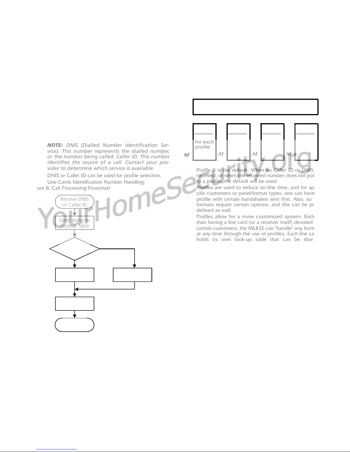
NOTE: DNIS (Dialled Number Identification Ser-
vice). This number represents the dialled number,
or the number being called. Caller ID: This number
identifies the source of a call. Contact your pro-
vider to determine which service is available.
DNIS or Caller ID can be used for profile selection.
Line Cards Identification Number Handling:
Figure 8, Call Processing Flowchart
Each profile is made up of Static Options and Dynamic
Options. The static options are the same for all pro-
files, but the dynamic options can be programmed
specifically per hunt groups, panel type, etc.
By receiving the DNIS or Caller ID, the appropriate
profile can be selected through a look-up table
"stored" on the line card.
Profile 0 is the default. When no Caller ID or DNIS is
received, or when the received number does not point
to a profile, the default will be used.
Profiles are used to reduce on-line time, and for spe-
cific customers or panel/format types, one can have a
profile with certain handshakes sent first. Also, some
formats require certain options, and this can be pre-
defined as well.
Profiles allow for a more customized system. Rather
than having a line card (or a receiver itself) devoted to
certain customers, the MLR2E can "handle" any format
at any time through the use of profiles. Each line card
holds its own look-up table that can be shared
through line pools, or shared within the entire receiver.
Two types of tables are available, but only one type can
be chosen. The first type, which consists of 10 000
entries, is used strictly with DNIS of up to 5-digits.
Table type 1:
DNIS receivedProfile # to be used
The second type is used if Caller ID is received, and
can consist of up to 10,000 entries, with up to 10 dig-
its.
Receive DNIS
or Caller ID
Send string to
Lookup Table
Point to Profile #
Use Options
from Profile
Use Profile 0
Corresponding
Profile?
Done
No
YES
Profile
0
(Default)
Profile
1
Profile
2~Profile
63
00
2F
Static Options - identical for all profiles
30 Dynamic
Options
unique
for each
profile
30 Dynamic
Options
30 Dynamic
Options
30 Dynamic
Options
~
AF AF AF AF
DNIS Received Profile# to be used
00001
00002
00003
...
99999
01
03
24
...
45
13
Table type 2:
The receiver will check through the Caller ID section if a
Caller ID number is received. If the Caller ID is received but
the Caller ID was not found, it will check in the virtual
receiver number and line number located in the dynamic
options or profiles, and use profile 0.
On a standard receiver, the Automation output would look
similar to the following:
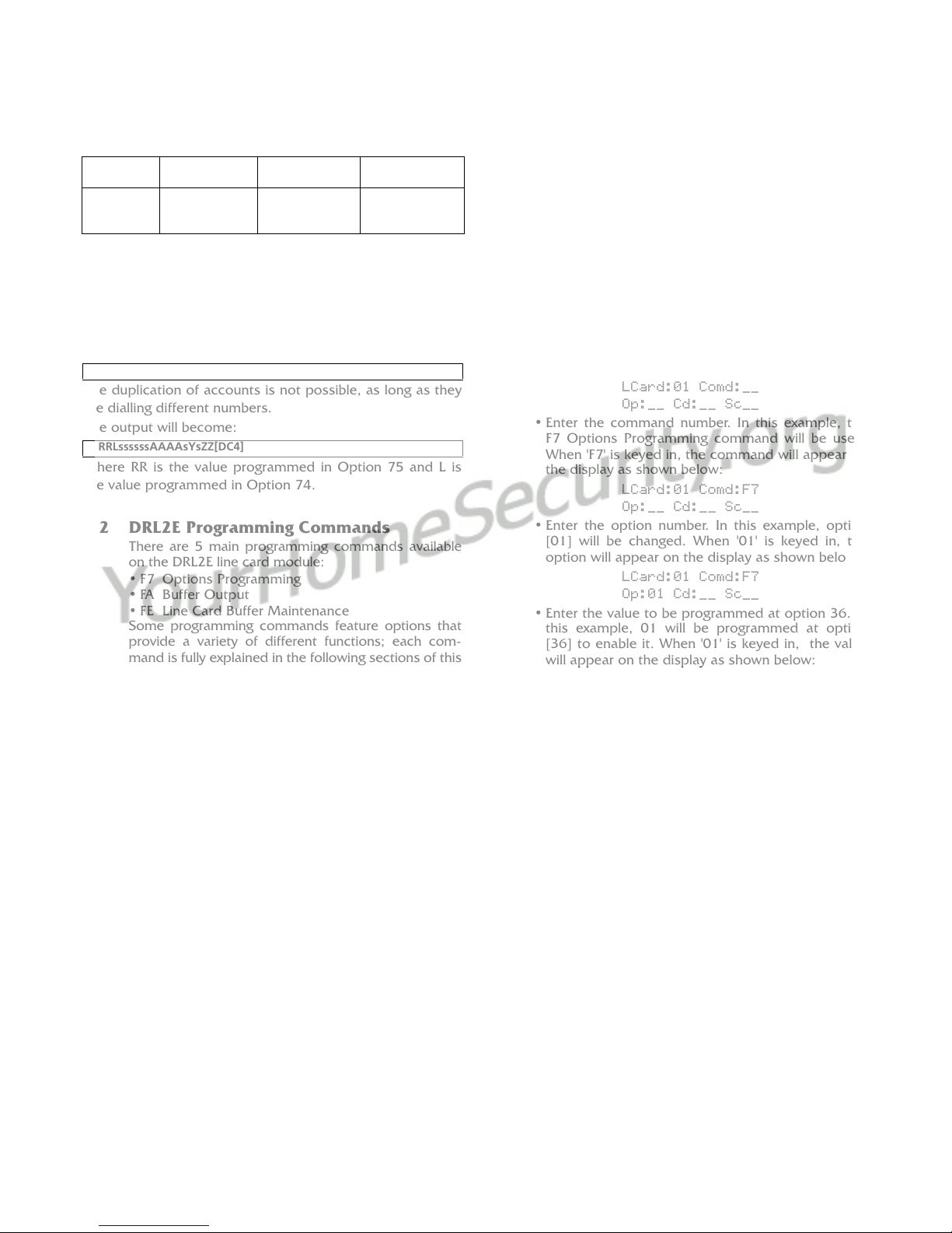
The duplication of accounts is not possible, as long as they
are dialling different numbers.
The output will become:
Where RR is the value programmed in Option 75 and L is
the value programmed in Option 74.
6.2 DRL2E Programming Commands
There are 5 main programming commands available
on the DRL2E line card module:
• F7 Options Programming
•FA BufferOutput
• FE Line Card Buffer Maintenance
Some programming commands feature options that
provide a variety of different functions; each com-
mand is fully explained in the following sections of this
manual.
Entering Commands
Commands are entered on the CPM2 keypad using
the following format:
LCard; Comd; Op; Cd; Sc
• LCard: 'Line Card' is the line card number; enter a
hexadecimal number from 01 to 0E for line cards 1
through 14
• Comd: 'Command' is the command; enter a com-
mand from the list above
• Op: 'Option' indicates a function that is part of a
command; the following sections of this manual
will explain which commands have options. Enter
a 2-digit hexadecimal number
• Cd: 'Code' is the code or value to be programmed
for the option; enter a 2-digit hexadecimal number
• Sc: 'Second Code' is a code or value that is only
used with SCADA commands; if required, enter a
2-digit hex number
Example:
The following is how to enter the programming pass-
word and program an option in the 'F7 Options Pro-
gramming' section:
Entering Data
• Press and hold the [C] button on the CPM2 until
the CPM2 displays the following message:
Enter PASS-WORD
****
The default password is 'CAFE'. Enter the password
using the CPM2 keypad.
• When the password is entered, the CPM2 will dis-
play this message:
LCard:__ Comd:__
Op:__ Cd:__ Sc__
• Enter the line card number. In this example, line
card 01 will be used. When '01' is keyed in, the
number will appear on the display as shown below:
LCard:01 Comd:__
Op:__ Cd:__ Sc__
• Enter the command number. In this example, the
F7 Options Programming command will be used.
When 'F7' is keyed in, the command will appear on
the display as shown below:
LCard:01 Comd:F7
Op:__ Cd:__ Sc__
• Enter the option number. In this example, option
[01] will be changed. When '01' is keyed in, the
option will appear on the display as shown below:
LCard:01 Comd:F7
Op:01 Cd:__ Sc__
• Enter the value to be programmed at option 36. In
this example, 01 will be programmed at option
[36] to enable it. When '01' is keyed in, the value
will appear on the display as shown below:
LCard:01 Comd:F7
Op:01 Cd:01 Sc__
Note that 'Sc' is not used and stays blank. After the
value is entered at 'Cd:', press [ACK] or [Escape] to
save the changes. NOTE: If the [Escape] button is
pressed before the value at 'Cd:' is entered, the
changes will not be saved.
Verifying Data
• To verify the changes just entered, press and hold
the [ACK] button on the DRL2E until this message
is displayed:
Display Options
ACK:menu SEL:sel
• Press the [SELECT] button to view the system con-
figuration; this message will be displayed:
L 1 Option #01
LCard NumB: 01
Press the [ACK] button to scroll forward through the
configuration displays until you reach option 36, or
press the [SELECT] button to scroll backwards through
the configuration displays. Press [ACK] and [SELECT]
together to return to the Standby mode.
Entry Num-
ber
Caller ID
Received
Represent Profile#
to be used
0001
0002
0003
14166654492
1938271623
8005764646
1-416-665-4492 01
03
24
1RRLssssssAAAAsYsZZ[DC4]
1RRLssssssAAAAsYsZZ[DC4]

14
6.2.1 F7 Line Card options Programming
Line Card-F7-Option-Code
The F7 Options Programming command is used to
change various operating parameters for the line card:
reporting codes, the line card number, buzzer opera-
tion and other features. Functions can also be changed
using the F7 command.
Refer to the example illustrated in 'Entering Com-
mands' in the 'DRL2E Programming Commands' sec-
tion of this manual.
Refer to the DRL2E Reference Sheets in the back of
this manual; be sure to record any programming
changes on these sheets.
NOTE: Options are programmed with 2 hexadecimal.
6.3 Static Options: [00] - [2F]
Option [00]: Reserved
Option [01]: Line Card Number - Default [00]
The line card Number provides a virtual identification
code for each DRL2E module. Hexadecimal numbers
'01' to 'FE' can be programmed in Option [01] to iden-
tify line cards.
Option [02]: Line Card Number Length - Default [0E]
This option is used to determine how many digits from
the line card number will be sent to the output. You
also have the option of displaying the number in hex or
decimal. Program Option 02 with one of the following:
01 Send only one Hex digit to the printer or computer
output (if you have a 2-digit line card number only
the last digit will be sent to the output)
02 Send 2 Hex digit line card number to the output
03 Send 3 Hex digit line card number to the output
(leading Zeros will be inserted prior to the line card
number)
0A Send 3-digit line card number as entered (no con-
version).
0D Send 3-digit line card number in decimal (conver-
sion from decimal to hex decimal
0E Send a 1-character line number 1-9, A-Z
Option [03]: Internal messages RS-232 - Default [01]
When this option is programmed as ‘00’, the DRL2E will
output its internal messages in the following format:
SRRL[#AAAA|Nxxyy]
If it is programmed as ’01’ internal messages will be
output as
0RRL[#AAAA|Nxxyy]
Where S, 0 (zero) = Protocol number
RR = Receiver number
L = Line number
AAAA = Account code, always 0000
Nxxyy = SIA event
Option [04]: 2-Way Audio Activation Time - Default
[00]*
Option [04] determines how long, in 10-second incre-
ments, the 2-way audio function will be active once it
is initiated. At the end of this time, the line card will
hang up the line. Program a value from "01" to "FF" for
10 seconds to 2550 seconds. Three (3) minutes is the
recommended length of time for the 2-way audio acti-
vation time. To disable the 2-way audio feature, pro-
gram Option [04] as "00".
NOTES: Enabling 2-way audio will affect NFPA 72
system loading requirements. Refer to Par. 4-5.3.2.2.2
of NFPA 72 for details.
If the alarm panel sends a listen-in code activation
request and audio is enabled for this format (Option
[7F]), the receiver will remain in two-way voice for a
period of 60 seconds even if the activation time is
not programmed.
* Use only with Model SG-MLR2E CE (not UL
listed).
Option [05]: Pre-H.S. Duration - Default [0A]
When the line card seizes the line, it will wait the time
programmed at Option [05]; then send the first hand-
shake. The value programmed (hex) at this location will
be multiplied by 100 ms. [e.g., 100 ms., 200 ms.] The
default is 0A, for 1000ms (100ms x default value).
The minimum time is 1 second. If the option is pro-
grammed with any value lower than 0A, the line card
will use a 1 second delay.
Options [06] to [0C]: Reserved
Option [0D]: Ring Select - Default [00]
Enables or disables the double ring detection. If pro-
grammed as 00, the line card will detect single ring. If
programmed as 01, the line card will detect the double
ring.
Option [0E-10]: Reserved
Option [11]: Hook-flash Enable/Disable - Default
[00]
Enables or disables ability to hookflash the phone line
and determines its duration in increments of 10 ms.
If programmed as 00, the option is disabled. If set to
anything else, you multiply the decimal equivalent of
the hex value by 10 ms and that is the duration. For
example, if hookflash time of 500 ms is wanted, pro-
gram Option 2A to 32 Hex.
Option [12]: Caller Source ID Option - Default [00]
Option [12] allows the line card to receive Caller Identi-
fication data or DNIS that is transmitted after the first
ring on the telephone line. The appropriate service must
be available and requested from the Telephone Com-
pany for this feature to be operational.
00
01
02
03
0X
Disabled
Standard Bellcore Caller ID
British Caller ID
Reserved for future use
Receive X (4 to 10) digits DTMF DNIS
15
General messages other than Caller ID or DNIS:
•Private Call: An anonymous indication is received
instead of the originating telephone number.
•No Call No.: An out-of-area or unavailable indication is
received instead of the originating telephone number.
•Unknown Call: The originating telephone number has
not been received or was not transmitted.
Option [13]: Caller Source to SG Computer - Default
[00]
Option [13] allows the transmission of the Caller Iden-
tification to the computer output. Program Option [13]
as one of the following:
00
01
02
Protocol
4RRL
URRL
Do not send to the computer
Send to the computer (North
American Caller ID)
Send to the computer (International
Caller ID)
NOTE: Option [12] must be programmed as "01" to
use Caller ID.
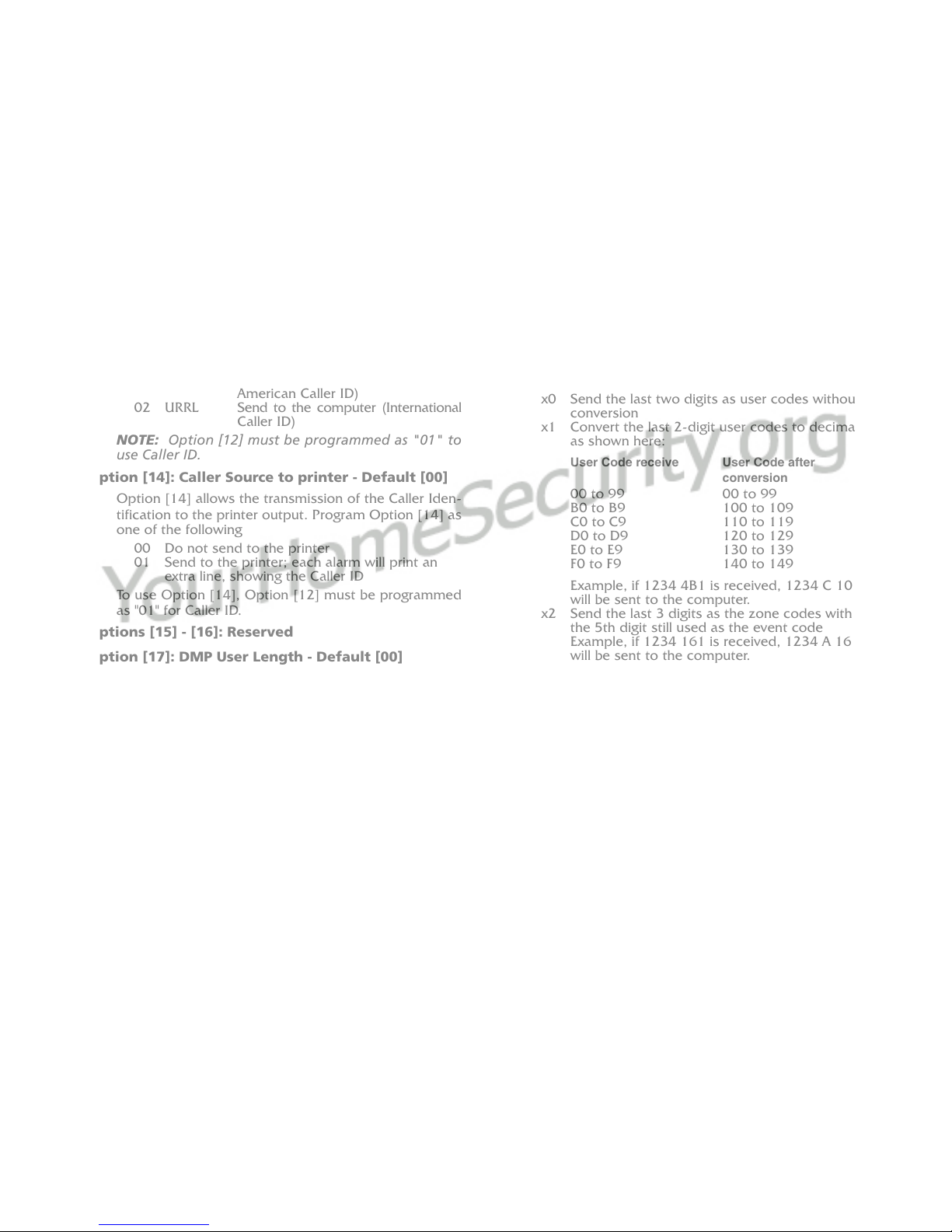
Option [14]: Caller Source to printer - Default [00]
Option [14] allows the transmission of the Caller Iden-
tification to the printer output. Program Option [14] as
one of the following
00
01 Do not send to the printer
Send to the printer; each alarm will print an
extra line, showing the Caller ID
To use Option [14], Option [12] must be programmed
as "01" for Caller ID.
Options [15] - [16]: Reserved
Option [17]: DMP User Length - Default [00]
Option 17 is for the variable length zone and user
numbers. The first digit in the option represents the
user number and the second digit represents the zone
number. For example, if Option 17 is set for 24 than
the receiver will output a 2-digit user number and a 4-
digit zone number. The default value is 00 for 2-digit
zone and 2-digit user number.
Option [18]: Sur-Gard DTMF 4/3 Format Output -
Default [00]
Each nibbles of this option controls how the 4/3 format
computer output string is formatted. The first nibble
allows for the user and group codes for openings and
closings to be combined. When programmed as “1x”,
group arming/disarming signals will be combined with
the user code into one signal which will be sent to the
computer.
Example, the following information may be sent to the
computer: (The printer output does not change)
Printer:
1234-B01 CloseGrp
1234-416 Close
1234-C02 OpenGrp
1234-532 Open
Computer:
1234 C1 16 (instead of 1234 C 01 and 1234 C 16)
1234 O2 32 (instead of 1234 O 02 and 1234 O 32)
If a user code is not received after the group opening/
closing, the message “1234 C1 FF” will be sent; “FF”
indicates that a user code was not received.
The second nibble of this option controls the user/zone
number conversion. The Sur-Gard 4/3 DTMF format is
made up of a 4-digit account code, a 1-digit event
code, and a 2-digit hexadecimal zone code or user
number. However, some central station software pack-
ages use a common event code and require decimal
user codes. This option allows the user codes to be
converted from hexadecimal to decimal to meet the
needs of the central station software. Program with
one of the following:
x0
x1
Send the last two digits as user codes without
conversion
Convert the last 2-digit user codes to decimal
as shown here:
User Code receive
00 to 99
B0 to B9
C0 to C9
D0 to D9
E0 to E9
F0 to F9
User Code after
conversion
00 to 99
100 to 109
110 to 119
120 to 129
130 to 139
140 to 149
x2
x3
Example, if 1234 4B1 is received, 1234 C 101
will be sent to the computer.
Send the last 3 digits as the zone codes with
the 5th digit still used as the event code
Example, if 1234 161 is received, 1234 A 161
will be sent to the computer.
When individual event codes are used, if 1234
401 is received, 1234 C 01 will be transmitted
to the computer. When common event codes
are used, if 1234 401 is received, 1234 Z 401
will be transmitted to the computer, where Z is
the common event code.
Send the last 3 digits as the zone codes and
convert the user codes only to decimal
NOTE: When the first nibble of the option is set to 1
the 3-digit user codes will be combined with the
group number as follows:
Code received
1234B01
12344B1
Code sent to computer
No transmission
1234 C1 101
Option [19]: Fault Call Counter - Default [00]
Option 19 is used for limiting the number of Fault Call
messages that are sent to the printer and computer.
The default setting will send a Fault Call alarm for every
10 Fault Calls. To have every Fault Call sent to the com-
puter and printer set Option 19 to 01.
Option [1A]: DNIS Input Sensitivity - Default [00]
NOTE: Do not change this option unless instructed
to do so by DSC Technical Support.
Option [1B]: Reserved

16
6.4 Dynamic Options: [30] - [FF]
Option [1C]: Busy Out - Default [00]
This option allows the line card to seize the phone line
in case of checksum error after download or when its
internal buffer is full after loss of communication with
the CPM. Program Option [1C] with one of the follow-
ing:
00
01
04
The line is seized if any of the conditions men-
tioned above occurs.
The line is NOT seized if any of the conditions
mentioned above occurs.
The line will be seized immediately
if the automation computer is absent.
NOTE: If the option is programmed to 01, the line
card will NOT buffer any new alarms once the inter-
nal buffer is full. Setting Option [1C] to 01 is NOT
RECOMMENDED.
Option [1D]: Input Sensitivity - Default [3F]
Option [1E]: Output Levels - Default [60]
Option [1F]: Debug Output - Default [00]
Set to 01 to enable. The debug mode should only be
used when required and disabled after use.
Option [20]: Reserved
Options [21] - [26]: Internal Use Only
Option [27]: Caller Source Process - Default [05]
This option determines how many digits of Caller ID or
DNIS the receiver will process.
0x - x is number of digits of DNIS or Caller ID to be
processed (range from 1 to A hex for Caller ID; range
from 1 to 05 for DNIS)
Options [28] - [29]: Reserved
Option [2A]: Hook-flash Delay - Default [00]
Time delay before hang-up option. Option value x
100ms to a maximum of 9.5 seconds.
Options [2B] - [2F]: Reserved
Options [30] - [3F]: 3/1 - 4/1 Digit 0-F
The DRL2E uses a unique Sur-Gard communication
format to transmit data through the CPM2 to the cen-
tral station computer. Event codes corresponding to
alarm codes in 10 to 40 Baud formats and DTMF 4/1
to 4/3 formats are used in this unique format to
enable the computer software to determine alarm
types.
The DRL2E will use the last digit of data received in
3/1 and 4/1 formats to determine the computer
event code. The event code will then be transmitted
to the central station computer. Refer to the DRL2E
Decoding Library for the complete set of event codes
used by the DRL2E. In Sections [30] through [3F],
program ASCII codes according to the Decoding
Library.
Do NOT use values other than 20-7F (ASCII).
Defaults: Option Value Code
30
31
32
33
34
35
36
37
38
39
3A
3B
3C
3D
3E
3F
41
41
41
41
41
41
41
41
41
52
41
4F
43
5C
52
54
A
A
A
A
A
A
A
A
A
R
A
O
C
/
R
T
Options [40] - [4F]: 3/2 - 4/2 Digit 0-F
The DRL2E will use the first digit following the
account code in 4/2, 3/1 extended or 3/2 formats to
determine the computer event code. The event code
will then be transmitted to the central station com-
puter. Refer to the DRL2E Decoding Library for the
complete set of event codes used by the DRL2E.
In Sections [40] through [4F], program ASCII codes
according to the Decoding Library. Do NOT use val-
ues other than 20-7F (ASCII).
Defaults: Option Value Code
40
41
42
43
44
45
46
47
48
49
4A
4B
4C
4D
4E
4F
41
41
41
41
41
41
41
41
41
52
41
4F
43
5C
52
54
A
A
A
A
A
A
A
A
A
R
A
O
C
/
R
T
Table of contents
Other Sur-Gard Receiver manuals

Sur-Gard
Sur-Gard SG-MLR2-E User manual

Sur-Gard
Sur-Gard SG System II User manual

Sur-Gard
Sur-Gard SG-System III User manual

Sur-Gard
Sur-Gard System Five User manual

Sur-Gard
Sur-Gard SG-System IV User manual

Sur-Gard
Sur-Gard SG-MLR2000 User manual

Sur-Gard
Sur-Gard System III User manual

Sur-Gard
Sur-Gard MLR2000 User manual

Sur-Gard
Sur-Gard System I User manual

Sur-Gard
Sur-Gard SG Security Communications MLR2-DG User manual


