SURAN ENDA EUP Series User manual
EN 60584
EN 60584
DIN 43710
EN 60584
EN 60584
EN 60584
EN 60584
EN 60584
EN 60584
EN 60751
EN 60751
°C °F
-199.9...600.0
-30.0....600.0°C
-30.0....600.0°C
-30.0...999.9°C
-30.0...400.0°C
-200...600
-30....600°C
-30....600°C
-30...1300°C
-30....400°C
-40...1700°C
-40...1700°C
°C
°C
-22.0....999.9 °F
-22.0....999.9 °F
-22.0....999.9 °F
-22.0....752.0 °F
-199.9...999.9
-22....2372 °F
-22......752
-40....3092
-40....3092
-328....1112
-22....1112 °F
-22....1112 °F
°F
°F
°F
°F
°F
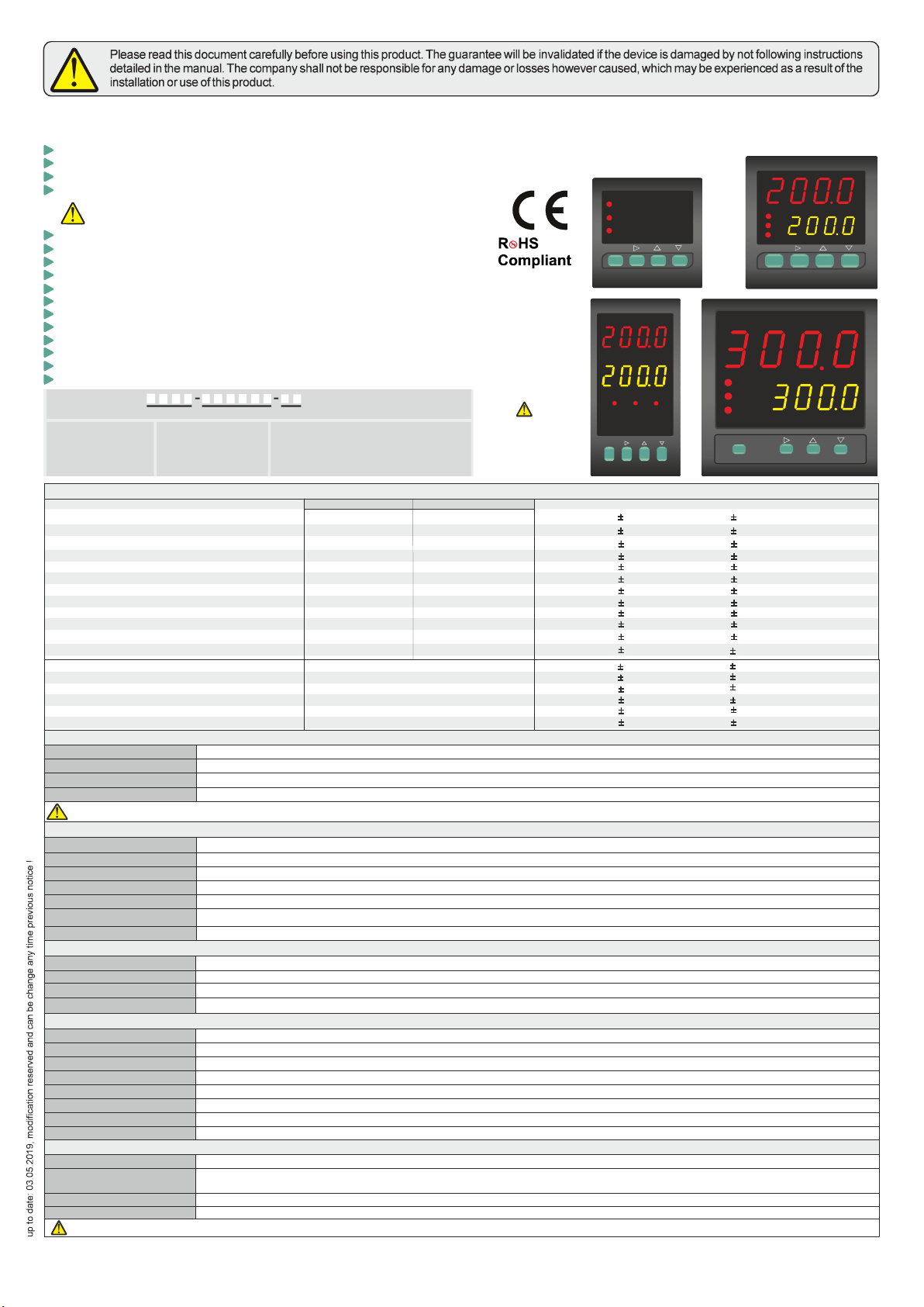
Order Code : EUP 1
1 - Size
4420.....48x48x87mm
7420.....72x72x97mm
8420.....48x96x87mm
9420.....96x96x50mm
2 -
230VAC...90 - 250V AC
SM...........9-30V DC /
7-24V AC
Supply Voltage 3 - RS..... RS-485
....
...
Blank
Modbus (Optional)
Modbus Available
(Optional / Specify at order).
N/A
202 3
4
DIN 43710
ENDA EU SERIES PID UNIVERSAL CONTROLLERP
Thank you for choosing niversal ontroller .ENDA EUP Series U C Devices
Dual setpoint value can be selected.
PT100 ,J, K, L, T, S, R sensor ( ) types can be selected.
0-20mA, 4-20mA, 0-10V, 2-10V, 0-25mV and 0-50mV input selections.
Auto calculation for PID parameters (SELF TUNE).
thermocouple
Three different feature can be assigned to digital input.
Three different feature can be assigned to F function key.
Soft-Start feature.
Analogue, SSR or Relay Output Control selection.
0-20mA and 4-20mAAnalogue Output Control selection.
Up to 16 steps Profile Control.
C/A2 Relay output can be used as second Alarm or Temperature Control output.
Heating/Cooling control selection.
.
In case of sensor failure, periodically, auto-periodically running or relay state can be selected.
Rs485 Modbus RTU communication protocol feature (Specify at order).
A1 Relay output as first Alarm or Cooling control output.programmable
Zero point input shift
Self tune for automatic PID calculation or
manually enter PID parameters if known.
Input Type Scale Range
J (Fe-CuNi) Thermocouple
L (Fe-CuNi) Thermocouple
J (Fe-CuNi) Thermocouple
L (Fe-CuNi) Thermocouple
K (NiCr-Ni) Thermocouple
K (NiCr-Ni) Thermocouple
T (Cu-CuNi) Thermocouple
T (Cu-CuNi) Thermocouple
S (Pt10Rh-Pt) Thermocouple
R (Pt13Rh-Pt) Thermocouple
PT100 Resistance Thermometer
PT100 Resistance Thermometer
0-20mA input
0-10V input
2-10V input
0-25mV input
0-50mV input
4-20mA input -1999...+9999 (max. scale range 10000)
-1999...+9999 (max. scale range 10000)
-1999...+9999 (max. scale range 10000)
-1999...+9999 (max. scale range 10000)
-1999...+9999 (max. scale range 10000)
-1999...+9999 (max. scale range 10000)
0,5% (for full scale)
0,5% (for full scale)
0,5% (for full scale)
0,5% (for full scale)
0,5% (for full scale)
0,5% (for full scale) 1 digit
1 digit
1 digit
1 digit
1 digit
1 digit
0,5% (for full scale)
0,5% (for full scale) 1 digit
1 digit
0,5% (for full scale) 1 digit
0,5% (for full scale) 1 digit
0,2% ( )for full scale 1 digit
0,2% ( )for full scale 1 digit
0,2% ( )for full scale
0,2% ( )for full scale
0,2% ( )for full scale
0,2% ( )for full scale
0,2% ( )for full scale
0,2% ( )for full scale
1 digit
1 digit
1 digit
1 digit
1 digit
1 digit
Accuracy
ENVIRONMENTAL CONDITIONS
Height
Ambient/storage temperature
Max. Relative humidity
Rated pollution degree
ELECTRICAL CHARACTERISTICS
Supply
Power consumption
Wiring
Line resistance
Data retention
EMC
Safety requirements
OUTPUTS
A1 Output
Life expectancy for relay
C/A2 Output
ANL/SSR Output
CONTROL
C typeontrol
Control algorithm
A/D converter
Sampling time
Proportional band
Control period
Hysteresis
Output power
HOUSING
Housing type
Dimensions
Weight
Enclosure material
90-250V AC, 50/60Hz or 9-30VDC / 7-24VAC %10 SMPS±
Max. 5VA
Power screw-terminal connections: 2.5mm²', Signal screw-terminal connections: 1,5mm².
EN 61326-1: 2013 (Performance criterion B satisfied for EN 61000-4-3 standard).
EEPROM (minimum 10 years)
Max. O100 hm
EN 61010-1: 2010 (Pollution degree 2, overvoltage category II)
Suitable for flush-panel mounting according to DIN 43 700.
EUP4420 : W48xH48xD87mm, EUP7420 : W72xH72xD97mm,
EUP8420 : W48xH96xD87mm, EUP9420 : W96xH96xD50mm.
Approx. 400g (250g for EUP4400) After packing.
Self extinguishing plastics
Single Setpoint and Alarm Control.
On-Off / P, PI, PD, PID (selection).
14 .bit
Min. 1 .00ms
Can be adjusted between .0 and .0 . If .0 , ON OFF c is selected.%0 %100 Pb=%0 - ontrol
Can be adjusted between and 125secs.1
Can be adjusted between 1 and 50°C/F.
Setpoint value ratio can be adjusted between %0 and %100 .
Relay : 250V AC, 8A (for resistive load), NO+NC (Control or Alarm2 Output selection).
Relay : 250V AC, 8A (for resistive load), NO (Alarm1 and Cooling Control Output selection).
Max. 2000m
0 ... +50°C/-25 ... +70°C
According to EN 60529; Front panel : IP6 Rear panel : IP205,
Max. SSR Output ; 0-20mA, 4-20mA, 24V 20mA. Max. load resistance ; 600 Ohm (12 bit 0.2% accuracy).
Relative humidity 80% for temperatures up to 31°C decreasing linearly to 50% relative humidity at 40°C.
Without load 30.000.000 switching; 250V AC, A (resistive load) 300.000 switching.8
KEEP AWAY device from exposed to corrosive, volatile and flammable gases or liquids and DO NOT USE the device in similar hazardous locations.
DO NOT clean the device with solvent (thinner, gasoline, acid etc.) and / or abrasive cleaning agents.
Please see EUPx420
Series Modbus Address
Map and Connection
Diagram Guide for
Modbus feature.
UNIVERSAL CONTROLLER
ENDA
EUP7420
C/A2
SSR
A1
PV
SV
F
C/A SET
SET
A1 DEL. A2 INS.
START STOP
UNIVERSAL CONTROLLER
ENDA
C/ASET F
SET
EUP4420
C/A2
A1
SSR PV
SV
1200
1200
START STOP
A1 DEL. A2 INS.
A1
C/A2
SSR
UNIVERSAL CONTROLLER
EUP9420
ENDA
PV
SV
SET
F
C/A SET
START STOP
A1 DEL. 2 INS.A
EUP8420
ENDA
UNIVERSAL CONTROLLER
SET
C/A SET F
C/A2
SSR
A1
PV
SV
START STOP
A1 DEL.A2 INS.
english
1. / 7
E-mail : info@suran-elektronik.de
Internet : www.suran-elektronik.de
Tel.: +49 (0)7451 / 625 617
Fax: +49 (0)7451 / 625 0650
SURAN Industrieelektronik
Dettinger Str. 9 / D-72160 Horb a.N
EUPx420-E-03052019

Ac.C.t.
25
Ac.o.t.
20
SET
C SET/A
F
F
F
F
F
C.s.Lo.
-30
C.s.Hi.
600
C. pb
4.0
C. ti
4.0
C. td
1.00
C.C.P.S.
0
C.Hys
2
C. Ct.
1
C.typ
HEAt
s.s.t.s.
0
C.E.p.s.
0
C.Ec.t.
E.PS.
Con.o.
inp.t.
J
Unit
°C
fltr.
20
C.o.sE
C-A2
offs.
0
d.Adr.
1
baud
9.60
d.in.C.
nonE
F.kE.C.
nonE
A2.S.L
-30
A2.S.H
600
A2.HY
2
A2.tP
INDE.
A2.St.
hi.
A2.Er.
ON
Al1.o. Al2.o. Conf..
A.o.Lo.
0
A.o.Hi.
100
A
A1
A2
B
A1.S.L
-30
CD
D1
D1
D3
A2
A2
A2
A2
A3
P.Con.
oFF
on
e C Selection.= Profil ontrol
=
=Standar ontrol
Profil ontrol
d c ling.
e c ling.
P.Con..
oFF
Ac.ot. = Full opening time duration
for Motorized Valve.
Can be adjusted between and 3
seconds. 2 00
Ac.C.t. =
Moto Controlling Period for
rized Valve.
Valve control output period as a
percentage of time duration. Can
be adjusted between 1% and 50%. This
parameter adjusts how often the valve is
operated, preventing unnecessary
operation.
Ac.ot.
D2
D2
D3
D4
D4
STOP
A2 INS.
STOP
A2 INS.
STOP
A2 INS.
STOP
A2 INS.
if the parameter set to
, this menu can not be
displayed (disabled).
C.O.SE.
A.Con.
If key is pressed while holding key, the "Programming Mode" is entered.
C SET/A
SET
F
ENTERING TO PROGRAMMING MODE
C.s.lo.
C.s.Hi.
= Lower limit for C/A2
Output control, setpoint value.
0Ca adjusted between andn be
C.s.Hi.
C.s.Lo.
= Upper limit for C/A2 Output
Control, setpoint value.
Can be adjusted between and
Upper scale value.
C. Pb
C.Pb
= P
for C/A2 Output 0 %
100
0.0%
roportional band value
..0
.0.%
Can be a ed
If parameter set to
, On-Off control will be accepted.
djust between and
C.Hys = H value for C/A2
O . ysteresis
utput
Can be a ed betweendjust between 1
and 50 °C. °C
C. ti
C. ti
= value for C/A2
Output Integral
.
0.0
Can be adjusted between 0.0 and 100.0
minutes. If parameter set to ,
integral will be disabled.
C. td
C. td
0.0
= /A2 Output value
0.00 25.00
C Derivative .
Asjustable between and
minutes. If parameter set to
, derivative will be disabled.
C. Ct. = A2 Output periodic time
duration.C/
1 250Adjustable between and
seconds.
C.p.st = A2 output power
percentage at A1 set value.
C/
0%
100%
Can be adjusted be andtween
.
C.E.C,t.
E.PS
C.E.P.S.
Auto
= Control type selection for
sensor failures.
If selected, controlling will be
performed to according to
proportional control parameter.
If is selected, controlling will be
performed to
before probe failure.
last recorded set value
percentage
C.E.P.s.
C.Pb 0.0
C.E.P.S. 0
C.E.P.S.
0
= A2 Output power percent
selection on probe failure.
C/
%0
%100
Can be adjusted between
If set to (On/Off
Control) and set to , output
will be OFF, on failure. If set to
different value from , output will be
ON, in case of failure.
and
.
S.S.t.S. = Soft start timer set value.
This parameter determines how
many minutes will be reached to the
setpoint value on power-up.
Can be adjusted between 0 and 250
minutes. If set to 0, the soft start
feature will be canceled and the
setpoint value will be reached
maximum speed.
C.typ. = Output controlling type
selection
HEAt.
CooL =
= Heating control
Cooling control
a1.s.l
A1.S.H
=
Can be adjusted between and0
parameter value.
Alarm1 set value lower
limit.
A1.S.H
600
a1.s.H
A1.S,L
=
Can be adjusted between and
upper scale value.
Alarm1 set value upper
limit.
A1.HY
2
a1.Hy = 1
Can be adjusted between 1 and
50°C.
Hysteresis of the Alarm
output.
A1.tP.
INDE.
A1.tp
indE.
dE.
bAnd
bAn.i
in.Co.
rE.Co
types= Alarm1 .
=
=
=
=
=
=
Six alarm types can be selected.
alarm
alarm
Independent
Deviation
Band alarm
Band with inhibition
A1 output independent
cooling control
A1 output relative cooling
control
Changes to this
parameter may cause
some parameter values to
change.
Input Type Selection Table
Resistance thermometer:
Thermocouple:
Pt.0
Pt.
PT100
P 100
with decimal
display (w.D.)
T without decimal
display (w.o.D.)
=
=
J.0
j
k.0
k
L.0
L
t.0
J Typ
J
K Typ
K
L Typ
L
T Typ
w.D.
Typ w.o.D.
w.D.
Typ w.o.D.
w.D.
Typ w.o.D.
w.D.
=
=
=
=
=
=
=
Analog output:
t
s
r
0-20
4-20
0-10
2-10
0-25
0-50
T Typ
S Typ
R Typ
0-20 mA
4-20 mA
0-10 V
2-10 V
0-25 mV
0-50 mV
=
=
=
=
=
=
=
=
=
ANNOTATIONS
A1.td
0
Onthedevicescreensshownonthispage;
-Firstlineindicatestheparametername,
-Secondlineindicatesthecurrentparameter'svalue.
Atthesametime,thevalueshowninthesecondlineis the
defaultvalueofthedevice.
ABCD
A1
A2
A3
Information tracking method
about the parameters
Parametername
Parametervalue(defaultvalue)
A1
A2
A3
B1
B2
B3
This parameter will be activated if the
parametersetto “0”. C.Pb
This parameter will be activated if the
parameterdifferentfrom“0”. C.Pb
This parameter will be activated if the
parametersetto“0”or setto
C.Pb
C.E.Ct E.P.S.
A1t.P
inC.o. rEC.o.or
Parameter can not be displayed
if is selected.
A1t.P inC.o.
rEC.o. orParameter will be activated if
is selected.
This parameter will be activated if the
parameter set to or and if the
parameter is different from “0”
A1.tp
in.Co. rE.Co.
A1.Pb
if the parameter set to
or , this menu can
not be displayed (disabled).
C.O.SE.
A.Con. C-A2
a2.s.l
A2.S.H
=
Can be adjusted between and0
parameter value.
Alarm2 set value lower
limit.
a2.s.H
A2.S,L
=
Can be adjusted between
and upper scale value.
Alarm2 set value upper
limit.
a2.Hy =
Can be adjusted between 1 and 50 °C.
Hysteresis of the Alarm2
output.
A2.tp
indE.
dE.
bAnd
2 types= Alarm .
=
=
=
Four alarm types can be selected.
alarm
alarm
Independent
Deviation
Band alarm
bAn.i = Band with inhibition
A2.st.
Hi
lo
= Status selection for Alarm2
Output
If is selected, A2 output is above
theAlarm2 set value ; ON. If is
selected, A2 Output is above the
Alarm2 set value ; OFF.
A2.Er.
on
off
= Alarm2 condition
selection on probe failure
=
=A2 Output is ON, in case of
probe failure.
A2 Output is OFF, in case of
probe failure.
inp.t. = Input Type Selection
Please see
for details at the bottom of this
page.
“Input Type Selection
Table”
Unit
°C
°F
= = °C
= °F
Selectable between and
Temperature Unit Selection.
fLtr. = Coefficient of Digital Filter.
Provides to filter for displayed value.
Adjustable between 1 and 200. If this
parameter set to 1, digital filter runs
quickly. If the parameter is set to 200,
filter runs slowly. This parameter value
shouldbe increased in interference
environments.
C.o.sE
C-A2
SSR
0-20
4-20
=
=
==
=
Control output selection.
=
C/A2 (Relay) output selection.
SSR output selection.
0-20 mA analogue output
4-20 mA analogue output
Control output selection for
motorized valve.
a.cON.
oFFS. =
The offset value is added to the
measurement value. This feature is used
to eliminate errors that may occur due to
the distance from the measuring probe to
the measuring point. Can be adjusted be-
tween -99 and 100°C. Default value is 0.
Offset Value.
D.aDr. =RS485 Connection Address.
Can be adjusted between 1 and 247.
baud =
Can be adjusted to off, 2.40, 4.80,
9.60, 19.20 and 38.40.
ModBus Baud Rate
d.in.C.
nonE
C2.S.A.
manu.
C.Ct
m.SEt
dSP.o.
= Digital input setting
parameter.
=
=
=
=
Digital input is closed.
if digital input is activated, 2nd
set value is used.
Manual mode start in case of
digital outputs are active and rational
output generated according to period
value in paremeter and
percentage value in parameter.
If the digital input is activated,
only temperature value will be indicated.
F.kE.C. =
nonE
C2.S.A.
manu.
dSP.o.
Function key setting
=
=
=
=
Function key is OFF.
2nd. set value can be used by
using function key.
Manual mode can be accessed
by using function key.
Temperature value will be
indicated by using function key.
A.o.Lo.
A.o.Hi.
= Minimum Output Percent for
Analog Output.
Can be adjusted between 0 and
A.o.Hi.
A.o.Lo.
= Maximum Analog Output
Percent for Analog Output.
Can be adjusted between and100
A1.st.
Hi
lo
= Status selection for
Alarm1 Output
If is selected, A1 output is above
theAlarm1 set value ; ON. If is
selected, A1 Output is above the
Alarm1 set value ; OFF.
A1.St.
Hi.
B1
B1 A1.Er.
on
off
= Alarm1 condition
selection on probe failure
=
=A1 Output is ON, in case of
probe failure.
A1 Output is OFF, in case of
probe failure.
A1.Er.
ON
A1.PB
0.0
B2 A1.Pb
A1.Pb
= A1 Output, proportional
band value.
Can be adjusted between % and
%.
If control will be accepted.
0
100 Parameter set to %0, On-
Off
A1.ti
0.0
B3 A1.ti
A1.ti
=
If parameter set to 0.0, integral
will be disabled.
A1 Output, integral value.
Can be adjusted between 0.0 and
100.0 minute.
A1.td
0
B3 A1.td
A1.td
=
If
Can be adjusted between 0.00 and 25.00
minutes. parameter set to
0.00, devirative will be disabled.
A1 output derivative value.
B3 A1.Ct
1
A1.Ct =
Can be adjusted between and
seconds 1 250
.
A1 Output Period Time.
B3 A1.ps
0
A1.PS = A1 output power percentage
at A1 set value.
Can be adjusted be andtween 0% 100%.
B2 A1.Ep
0
A1.EP. = A1 Output power percent
selection on probe failure.
Can be adjusted between % %0 and 100 .
Page 3
Page 3
inp.t = Input Type Selection
2. / 7
E-mail : info@suran-elektronik.de
Internet : www.suran-elektronik.de
Tel.: +49 (0)7451 / 625 617
Fax: +49 (0)7451 / 625 0650
SURAN Industrieelektronik
Dettinger Str. 9 / D-72160 Horb a.N
EUPx420-E-03052019

RUNNING MODE
Alternatively, by pressing key "Running Mode" is entered and by pressing both keys at once, settings automatically
saved and device returns to the "Running Mode" (to the home screen).
During in "Programming Mode", if no key is pressed for 20 sec, settings automatically saved and device returns to the "Running Mode" (to the
home screen).
SET
C SET/A
F
SET
C SET/A
F
F
pfa
400
____
400
400
----
No communication with
sensor. (Sensor and/or
cable broken or not
connected)
Temperature value is
higher than scale.
Temperature value is
lower than scale.
ERROR MESSAGES
F
s.t.us.
Pid.t.
25
s.tun.
s.t.us.
s.tun.
R.trs.
nonE
R.o.Lo.
-30
R.o.Hi.
600
d.P.SE.
0
u.S.Lo.
1999
-
u.S.Hi.
2000
D
E
Conf..
D5
D6
D6
D7
D7
D7
START
A1 DEL.
C/A SET
SET
STOP
A2 INS.
C/A SET
SET
C/A SET
SET
R.trS. = Control Parameter for
Retransmission Output.
Retransmission
retransmission output.
retransmissionoutput.
OFF.
0-20mA Analog
4 - 2 0 mA A n a l o g
nonE
0-20
4-20
=
=
=
R.o.Lo.
R.o.Hi.
= Lower Scale Value for
R Output.
Can be adjusted between lower scale
value and .
etransmission
R.o.Ho.
R.o.Lo.
= Output.
Can be adjusted between and
upper scale value.
Upper Scale Value for
Retransmission
d.P.SE. =
mA .
Decimal Point selection for
Inputs
Can be adjusted between 0 and 0.000
u.S.Lo.
u.S.Hi.
= mA
-1999
( - 10 )
Lower Scale Value for
Inputs.
Can be adjusted between and
.
u.S.Hi.
u.S.lo
= mA
+ 10
9999.
Upper Scale Value for
Inputs.
Can be adjusted between ( )
and
SET SET
SET
SET
C SET/A C SET/A C SET/A C SET/A
When holding key, selected parameter flashes and desired alue can be adjusted by
using keys.
v
If key is pressed and held 0.6 seconds, the value of the selected parameter changes rapidly.
If waited enough, the value increases 100 at each step. After 1 second following the realese of the
key, initial condition is returned. The same procedure is valid for the decrement key.
Parameter Setting Diagram
SET
C SET/A
s.t.us.
pid.t.
tE.hi
Pid.t.
C.Pb Ct C.dt C.Ct.
S.tun.
s.t.sc. p.yEs SECU
= Self tune Control Parameter.
If keys are pressed together, main screen
displayed and if the temperature is not high,
message flashes on display and the self tune process
starts automatically. If the initial temperature is higher to
self-tune, . message appears and waits until the
temperature goes down. Then message appears
and self tune procedure starts automatically. After the self
tune procedure, , , and values are
stored in memory and "Running mode" (main screen) is
entered. After the successful self tune completion,
menu will be removed automatically. In order to re-tune,
parameter should be set to in menu.
SET
CSET
Stopping self tune
“Programming Mode"
When the self-tune operation needs to be terminated,
should be entered by using
keys and menu should be selected.
By using key, parameter is selected and self-
tune process can be terminated by pressing with together
keys.
S.tun
S.t.uS
SET
CSET
SET
CSET
d.SEl..
1
S.num.
8
a2.P.c..
off
a1.P.c..
off
P.on.t
StoP
C.Con..
off
SE.i.P.
50
t.bAS.
Min
P.CnF..
F
F
d.sEl. = Display Selection Parameter.
Can be selected between 1 and 10. If 1 is selected, only
the process value is displayed. If 2 and up values are
selected, the step number and the process value are
displayed alternately if 2 or more segment profiles are
programmed. Entered number indicates how many
seconds "step number" will be displayed. For example, if
4 is entered, step number will be displayed for 1 second
in 4 seconds.
s.num = Number of Maximum Steps.
Can be selected between 0 and 16. The numbers 1
through 16 indicate the maximum program step to run. If
0 is selected, the thermostat and timer mode are
switched on. In this mode, when the temperature reaches
the set value, the timer is activated and the Alarm1
contact is active at the end of the time.
P.ont.
StoP
Cont.
= Behavior Selection on Power-up.
If is selected, program stops when the power is
turned off and on (restart, power loss etc.) and the
program wait for restarting.
If is selected, program will resume on power-up.
SE.i.p.
SE.i.P. C.Hi.L.
If S.num
SE.i.p.
S.num
SE.i.p.
= Step Increment Parameter.
= 1 to 8
= 0
Parameter takes values between "0" and
parameter. is selected, at the end of
time, Device waits until the difference between the
process value and the target temperature is less than or
equal to value and then passes to the next step.
If is selected, timer is stopped and LED
flashes until the difference between the target
temperature and the process value is less than or equal
to
t.bas.
sEC. min.
SEC.
min.
= .Time Units
=
=
Can be selected as or
Second-time unit selection.
Minute-time unit selection.
C.Con.
off
on
= Continuous Control Selection.
=
=
Temperature control is switched off at the end of
the profile.
Temperature is kept constant at the last set
value at the end of the profile.
A1.p.c.
off A1.tP.
on
= A1 Output Control Profile.
=
=
A1 output runs according to parameter
selection.
A1 output runs as programmed in profile steps.
STOP
A2 INS.
if the parameter set to
, this menu can not be
displayed(disabled).
P.Con.
oFF
A2.p.c.
off A2.tP.
on
= A2 Output Control Profile.
=
=
A2 output runs according to parameter
selection.
A2 output runs as programmed in profile steps.
F
Co.sc.
p.yEs
a.1..sc.
p.yEs
a.2.sc.
p.yEs
Cn.sC.
p.yEs
S.t.sc.
p.yEs
S.Cod.
0
SECU.
D1
D2
D4
G
D3
D5
D6
D7
STOP
A2 INS.
p.C.sC.
p.yEs
This parameter availble in RS485-Modbus
devicesonly.
This parameter can be displayed if the
parametersetto “0-20”or“4-20”.
CoSE.
This parameter can be displayed if the
parametersetto “ ”.
CoSE.
C-A2
This parameter can be displayed if the
parameter set to “ ” and if the
parametersetto “0-20”or“4-20”.
CoSE.
RtrSC-A2
This parameter can be displayed if the
parametersetto “ ”,“mA” or“V”.
inPt
mV
This parameter can be displayed if the
Parametersetto
C.o.SE
A.con.
S.Cod = Security menu access code.
442To accessing security menu, should be entered.
While code ( , by
held down the key and by pressing
key for 4 seconds, message
appears and default mode is entered.
0S.Cod S.Cod 0
dEfP
= )
SET
Cosc. CoN.o
nonE
P.yEs
P. no
=
=
=
=
Security Access for Parameter.
Menu invisible.
Modification can be done.
Only visible.
a.1.sc. al1.o.
nonE
P.yEs
P. no
= Security Access Level for
Parameter.
=
=
= Only visible.
Menu invisible.
Modification can be done.
a.2.sc. al2..o.
nonE
P.yEs
P. no
= Security Access for Parameter.
=
=
= Only visible.
Menu invisible.
Modification can be done.
Cn.sC. Conf.
nonE
P.yEs
P. no
= Security Access for Parameter.
=
=
= Only visible.
Menu invisible.
Modification can be done.
S.t.Sc.. S.tun...
nonE
P.yEs
= Security Access for Parameter.
=
= Menu invisible.
Modification can be done.
P.C.SC. PCnF.
nonE
P.yEs
P. no
= Security Access Level for
Parameter.
=
=
= Only visible.
Menu invisible.
Modification can be done.
Changes to this parameter may cause some
parametervaluestochange.
Please see EUPx420 Series Modbus
Address Map and Connection
Diagram Guide for Modbus feature.
P. 2
re-transmission ( ):Measured value forwarding
Input signal transmittered to analogue output.
Page 2
3. / 7
E-mail : info@suran-elektronik.de
Internet : www.suran-elektronik.de
Tel.: +49 (0)7451 / 625 617
Fax: +49 (0)7451 / 625 0650
SURAN Industrieelektronik
Dettinger Str. 9 / D-72160 Horb a.N
EUPx420-E-03052019

250
400
C1.SE.
400
C2.SE.
400
a1.SE.
500
a2.SE.
500
m.SEt
50
C1.SE.
400
C2.SE.
400
a1.SE.
500
a2.SE.
500
m.SEt
50
C1.SE.
399
C2.SE.
399
a1.SE.
499
a2SE.
499
m.SEt
49
START
A1 DEL.
START
A1 DEL.
START
A1 DEL.
START
A1 DEL.
START
A1 DEL.
STOP
A2 INS.
STOP
A2 INS.
STOP
A2 INS.
STOP
A2 INS.
STOP
A2 INS.
SET
C SET/A
SET
C SET/A
SETTING OPTIONS IN RUNNING MODE
SETTING UP ALARM CONTROL AND SETPOINT VALUES
if the parameter set to
, this menu can be
displayed.
P.Con.
oFF
3 seconds
later
If one of the or
parameters are set
to the value, this
parameter can be displayed.
d.in.c.
f.kE.c.
C2.S.A.
If the parameter is
set to SSR out, this
parameter can be displayed.
C.O.SE.
If one of the or
parameters are set
to the and if
is different from 0, this
parameter can be displayed.
d.in.c.
f.kE.c.
mAnu. C. Pb
250
400
C.SEt.
200
timE
60
C.SEt
200
timE
60
C.SEt
199
timE
59
START
A1 DEL.
START
A1 DEL.
STOP
A2 INS.
STOP
A2 INS.
SET
C SET/A
SET
C SET/A
SETTING UP TIMER/THERMOSTAT SETPOINT VALUES
A2.os.
C.o.SE
SSr 0-20 4-20 A2.P.c.
A2.os. on
Parameter :
This parameter appears if the
parameter set to , or and whith the parameter is
set to on. If is set to , A2 output state becomes on. At the end of
the duration or if STOP key is pressed, A2 state will be off (this parameter is
described in PC16 coils at ModBus address map).
A2.oS.
on
A2.os.
on
A2.os.
off
START
A1 DEL.
STOP
A2 INS.
if the parameter set to or
, this
menu can be displayed.
P.Con. ON
S.num. parameter set to 0
Red LED indicators for C and outputs.ontrol,Alarm1 Analog/SSR
( 7 ) Status Indicators
( 3 ),( 4 ),( 5 ),( 6 ) Keypads
Mi ro switchc
( 2 ) Timer Indicator
PV 7 4 , SV 7 4 LED display. Character height : PV and SV display 7.2MSegment digits red LED Segment digits yellow
( 1 ) PV SVand indicators
( 6 ) Parameter set key in “Programming Mode”Control and Alarm set key in “Runnig Mode”.
( 5 ) “Running Mode”. Menu selection key in “Programming Mode”.Selectable function key
( 4 ) .Decrement key By pressing this key in “Running Mode”, software version can be displayed.
Parameter selection key in “Programming Mode”.
( 3 ) Increment key in “Running and Programming Mode”. Parameter selection key in “Programming Mode”.
( 1 ) Indicates measured value and set values in “Running Mode”. Indicates the parameters and names in
“Programming Mode”.
( 2 ) Lights up, if timer is displayed and flashes while timer is running.
TERMS AND DISPLAY
Indicates during the timer displayed and flashes while timer running in “Profile Mode”.
( 7 )
UNIVERSAL CONTROLLER
ENDA
SV
A1
PV
AN/SSR
C/A2
EU 442P 0
C/A SET
F
SET
START STOP
A1 DEL. A2 INS.
1200
1200
ADJUSTING PROFILE STEP PARAMETERS
tE.16
500
ti.16
40
tE.01 = Target temperature value for 1st step.
By hold down to key, desired value can be adjusted with and keys.
tE.16 = Targettemperaturevaluefor16thstep.
Byholdingdownto key,desiredvaluecanbeadjustedbyusing navigationkeys.
If key is pressed in "Running Mode", step programming menu can be entered.
Programming Mode
C/A2
C/A2
AN/SSR
AN/SSR
A1
A1
The procedure for further ramp steps is repeated as described above.
If parameter is , this
section can be entered.
p.co. on
ti.01
40
sg.01
AL-S.
sg.01
AL-S.
sg.01
AL-S.
C/A2 C/A2 C/A2 C/A2
AN/SSR AN/SSR AN/SSR AN/SSR
A1 A1 A1 A1
F F F
START
A1 DEL.
STOP
A2 INS.
START
A1 DEL.
STOP
A2 INS.
START
A1 DEL.
STOP
A2 INS.
START
A1 DEL.
STOP
A2 INS.
500
40.
tE.01
500
ti.01
40
C/A2
C/A2
C/A2
AN/SSR
AN/SSR
AN/SSR
A1
A1
A1
START
A1 DEL.
STOP
A2 INS.
START
A1 DEL.
STOP
A2 INS.
SET
C SET/A
SET
C SET/A
SET
C SET/A
SET
C SET/A
SET
C SET/A
F
F
SET
C SET/A
Con.o.
START
A1 DEL.
STOP
A2 INS.
ti.01 = Time value for 1st step.
By hold down to key, desired value can be adjusted with and keys.
SET
C SET/A
START
A1 DEL.
STOP
A2 INS.
ti.16 = Timevaluefor16thstep.
Byholdingdownto key,desiredvaluecanbeadjustedbyusing navigationkeys.
START
A1 DEL.
STOP
A2 INS.
SET
C SET/A
Attention !
In order for the alarm
outputs to function as set
in the profile steps,
and parameters
must be set to before
applying the profile.
A1.P.c.
A2.P.c.
on
pfa
400
____
400
400
----
No communication
with sensor. (Sensor
and/or cable broken
or not connected)
Temperature value is
higher than scale.
Temperature value
is lower than scale.
ERROR MESSAGES
3 seconds
later 3 seconds
later 3 seconds
later
ti.01
60
C/A2
AN/SSR
A1
Sg.01
C/A2
AN/SSR
A1
sg.01
dEl.
C/A2
AN/SSR
A1
Hold down
for
2 seconds
Release
the
keys
FFF
START
A1 DEL.
START
A1 DEL.
If key is pressed, upper display indicates the step number and lower display indicates the message. In this point by hold
down to key, Al1 output can be set to on or off with key. Also, Al2 output can be set to on or off with key.
AL-S.
START
A1 DEL.
STOP
A2 INS.
F
F
If key is hold down for 2 s , step number flashes at the upper display. During holding down the key and by pressing to key,
message displayed and current profile will exited and next step value shifted up. Or, if key is pressed, message appears
and the next steps are shifted to the next and a new step is inserted. When keys are released, new values of the step are displayed.
.
dEl.. inS.
FF
START
A1 DEL.
STOP
A2 INS.
Delete or insert from
ramp steps:
4. / 7
E-mail : info@suran-elektronik.de
Internet : www.suran-elektronik.de
Tel.: +49 (0)7451 / 625 617
Fax: +49 (0)7451 / 625 0650
SURAN Industrieelektronik
Dettinger Str. 9 / D-72160 Horb a.N
EUPx420-E-03052019

ALARM1 AND ALARM2 OUTPUT TYPES
A1.St. Hi=
A1.St. lo=
=A1.St. Lo
=A1.St. Hi
ASV
SV SV
SV
SV+ASV
SV+ASV
SV-ASV
OFF
OFF
OFF
OFF
-300
300
+300
300
ON
ON
ON
ON
a1,Hy A1.Hy
A1.Hy
A1.Hy
PROFILE CONTROL OUTPUT DIAGRAMS
TIMER / THERMOSTAT OUTPUT DIAGRAMS
SNuM 1= SNuM 1=
C.Con on= C.Con off=
tE.01 tE.01
ti.1 ti.1
ti.1 ti.1
Temperature
sE.i.P. sE.i.P.
S.num must be set to 1 for single step program.
SV
A1 OUTPUT
(VALVE CLOSE)
Full opening time
C/A2 OUTPUT
(VALVE OPEN)
The minimum time between two contact
outputs can be as long as the value.Ac.C.t
Power ON
Motorized valve connection must be applied as shown figure above (if the motorized valve electrical values are incompatible with EUPx420 contact output values, an
additional contactor must be connected).And parameter in the EUPx420 must be selected as . Full opening time of the motorized valve connected to the
deviceisenteredin parameterasseconds.Fullopeningtimemustbeenteredto parameteraspercentageformotorizedvalverunning-uptime.
C.o.SE. A.con.
Ac.o.t. Ac.C.t
17
A1 AC 250V 2A
RESISTIVE LOAD
(VALVE CLOSE)
CLOSE
16
C/A2
AC 250V 2A
RESISTIVE LOAD
(VALVE OPEN)
15
14
13
OPEN NL
MOTORIZED VALVE CONNECTION AND SETTINGS
Independent Alarm
A1.tp. indE=Deviation Alarm
= A1.tp dE.
Band
=
Alarm
A1.tp. bAnd
SV = CONT output set value ASV = Alarm output set value
(ASV min. =-300, ASV maks. = +300)
(ASV min. = beginning of scale
ASV max. = end of scale) (ASV min. = 0, ASV ma . = +300)x
SV =CONT set ASV = setoutput value A1 output value
=
Band Alarm With Inhibition
A1,tp. bAn.i
ON
OFF
Beginning Band alarm is possible
SV
SV+ASV
SV-ASV
ON
OFF
Band alarm is possible
Beginning
SV
SV+ASV
SV-ASV
SV =Set point of CONT output ASV = Set point of A1 output (ASV min. = 0, ASV max. = 300 )
Time
Time
Temperature
START
Key
Time
Time
START
Key
Temperature
Time
Time
S.NuM 0= S.NuM 0=
C.Con on= C.Con off=
C.SEt C.SEt
A1 Out
A2 Out A2 Out
A1 Out
timE tiME
timE+Hold timE
timE timE
START
key START
key
START
key START
key START
key
STOP
key STOP
key
Hold
sE.i.P. sE.i.P.
A2 Output runs if the
parameter is set
to , or
and with the
parameterissetto
C.o.SE
SSr, 0-20 4-
20 A2.P.c.
on
Temperature
Time
Time
START
key STOP
key START
key START
key STOP
key
6. / 7
E-mail : info@suran-elektronik.de
Internet : www.suran-elektronik.de
Tel.: +49 (0)7451 / 625 617
Fax: +49 (0)7451 / 625 0650
SURAN Industrieelektronik
Dettinger Str. 9 / D-72160 Horb a.N
EUPx420-E-03052019

18
29
716 17
615
310
413
514
ENDA
INDUSTRIAL ELECTRONICS
EUP 309420-2 VAC
PID CONTROLLERUNIVERSAL
-
8 680407 725755
Made in Turkey
11 12
18
29
716 17
615
310
413
514
-
11 12 18
29
716 17
615
310
413
514
ENDA
INDUSTRIAL ELECTRONICS
EUP 309420-2 VAC-RS
PID CONTROLLERUNIVERSAL
-
8 680407 725762
Made in Turkey
11 12
18
29
716 17
615
310
413
514
-
11 12
INDUSTRIAL ELECTRONICS INDUSTRIAL ELECTRONICS
EUP 2
ID UNIVERSAL
44 0-230VAC
P CONTROLLER EUP 2 -RS
ID UNIVERSAL
44 0-230VAC
P CONTROLLER
ENDA ENDA
SN: XXXXXXXXX SN: XXXXXXXXX
C/A2 C/A2
A1 A1
AC 250V A
RESISTIVE LOAD
8AC 250V A
RESISTIVE LOAD
8
AC 250V A
RESISTIVE LOAD
8AC 250V A
RESISTIVE LOAD
8
ANL/SSR
OUT ANL/SSR
OUT
DIN
mA,mV, V mA,mV, V
DIN
16 16
88
17 17
99
10 10
11 11
11
12 12
22
13 13
33
14 14
44
15 15
55
66
77
++
--
90-250V AC ±10%
50/60Hz 5VA 90-250V AC ±10%
50/60Hz 5VA
-
-
+
+TC
TC
PT100
PT100
-
+
RS- 485 A
B
RS-485 COM.
ENDA INDUSTRIAL ELECTRONICS
EUP 7420 230
UNIVERSAL
- VAC
PID CONTROLLER
V AC +10% -20%
50/60Hz 7VA
90-250
C / A2
AC 250V A
RESISTIVE
LOAD
8
A1
AC 250V A
RESISTIVE
LOAD
8
11
12
13
14
15
16
17
SN: XXXXXXXXX
8 680407 725632
Made in Turkey
SSR
OUT
+
-
TC
-
Pt 100
9
8
5
4
3
2
1
10
7
6DIN
ENDA INDUSTRIAL ELECTRONICS
EUP 7420 230 - RS
UNIVERSAL
- VAC
PID CONTROLLER
V AC +10% -20%
50/60Hz 7VA
90-250
C / A2
AC 250V A
RESISTIVE
LOAD
8
A1
AC 250V A
RESISTIVE
LOAD
8
11
12
13
14
15
16
17
SN: XXXXXXXXX
8 680407 725649
Made in Turkey
-
+
RS-485
COM.
RS- 485
SSR
OUT
A
B
+
-
TC
-
Pt 100
9
8
5
4
3
2
1
10
7
6DIN
+ mA,mV,V
+ mA,mV,V
+ mA,mV,V + mA,mV,V
SSR
OUT
+
-
SN: XXXXXXXXX
15
16
17
18
19
20
21
V AC +10% -20%
50/60Hz 7VA
90-250
C / A2
AC 250V A
RESISTIVE
LOAD
8
A1
AC 250V A
RESISTIVE
LOAD
8
TC
-
Pt 100
11
10
7
6
5
4
3
12
8 680407 725694
Made in Turkey
9
8DIN
-
+
RS-485
COM.
RS- 485
SSR
OUT
A
B
+
-
SN: XXXXXXXXX
15
16
17
18
19
20
21
V AC +10% -20%
50/60Hz 7VA
90-250
C / A2
AC 250V A
RESISTIVE
LOAD
8
A1
AC 250V A
RESISTIVE
LOAD
8
TC
-
Pt 100
11
10
7
6
5
4
3
12
8 680407 725700
Made in Turkey
9
8DIN
MULTI-STEP PROFILE CONTROL OUTPUT GRAPHICS
If set toC.Con on
If set toC.Con oFF
30
20
100°C
200°C
300°C
60 60
40
tE.01 100=
ti.01 = 30 ti.02 = 20 ti.03 60= ti.04 = 40 ti.05 = 60
tE..02 100= tE..03 300= tE..04 300= tE..05 100=
ti.S.1 ti.S.2 ti.S..3 ti.S..4
ti.S.5
Time (minute or sec)
Step1
Step1 Step2 Step3 Step4 Step5
Step2 Step3 Step4 Step5
Program returns to the beginning at this
point and stops. Waits for the START
buttontobepressedagain.
A2
A1
ON
A1
Target Temperature
Time OFF OFF
S.num should be set to 5
for five step program.
OFF
ON
OFF
A2 ON OFF OFF
ON
9
10
6
8
EUP4420 EUP7420 EUP8420
EUP4420 EUP7420 EUP8420 EUP9420
9
10
9
10 12
11
11
12
10
9
10
8
EUP9420
8
9
9
10
8
PT100 PT100 PT100 PT100
EUP4420 EUP7420 EUP8420 EUP9420
Fuse
F 100 mA
250V AC
Supply
230V AC or 24V AC
184-253V AC
or
21.6-26.4V AC
50/60Hz 5VA
Anahtar
CONNECTION DIAGRAM
NOTE :
SUPPLY VOLTAGE
Line
Neutral
Fuse should
be connected.
Cable Size : 1,5mm²
SENSOR INPUT:
ForJ-K-T-SandR Thermocouples:
Use the correct compensating cable. Do
not make any supplement to cables.
Connect the thermocouple cables to the
rightplacesat theinputterminal.
Forresistance(PT100)Sensor:
In order to using 2-wire resistance sensors
(PT100), 8th and 9thterminals must be short
circuited on EUP4420, EUP7420 and
EUP9420 devices. Also on EUP8420
devices, 10th and 11th terminals must be
short circuited. Please check connection
diagramscarefully.
Logic output of the instrument is not electrically
insulated from the internal circuits. Therefore, when
using a grounding thermocouple, donot connect the
logicoutputterminalstotheground.
1)
2)
Mainssupplycordsshallmeettherequirementsof
IEC60227orIEC60245.
In accordance with the safety regulations, the
power supply switch shall bring the identification of
the relevant instrument and it should be easily
accessiblebytheoperator.
Note :
Holding screw
0.4-0.5Nm
Equipment is protected throughout
by DOUBLE INSULATION.
MODBUS CONNECTION
PleaseseeEUPx420SeriesModbusAddressMapandConnectionDiagramGuideforModbusfeature.
* MODBUS CONNECTION DIAGRAM
120 Ohm
Master Slave - 1 Up to 127 slave devices
can be controlled.
Slave - 2 Slave - 127
A
BA
B
A
BA
B
Termination should be accomplished by
attaching 120 Ohm resistors to the start
andattheend ofthecommunicationline.
* Applies todeviceswithModbusfunction.
5. / 7
E-mail : info@suran-elektronik.de
Internet : www.suran-elektronik.de
Tel.: +49 (0)7451 / 625 617
Fax: +49 (0)7451 / 625 0650
SURAN Industrieelektronik
Dettinger Str. 9 / D-72160 Horb a.N
EUPx420-E-03052019
for more information see additional sheets for Modbus command list

EUP9420
EUP7420 EUP8420
EUP4420
98mm
DIMENSIONS
50mm
2
1
UNIVERSAL CONTROLLER
ENDA
C/A SET F
SET
EUP4420
C/A2
A1
SSR PV
SV
1200
1200
START STOP
A1 DEL. A2 INS.
UNIVERSAL CONTROLLER
ENDA
EUP7420
C/A2
SSR
A1
PV
SV
F
C/A SET
SET
A1 DEL. A2 INS.
START STOP
A1
C/A2
SSR
UNIVERSAL CONTROLLER
EUP9420
ENDA
PV
SV
SET
F
C/A SET
START STOP
A1 DEL. 2 INS.A
Depth
Connection
Cables Flush mounting
clamp
Ambient temperature
sensor
Depth
Connection
Cables
Flush mounting
clamp
Gasket
Panel
Panel
Ambient
temperature
sensor
Connection
Cables
Flush mounting
clamp
Gasket
Panel
Ambient
temperature
sensor
Depth
To removing the device from the panel:
- and .
While pressing both side of the device
in direction , push it in direction
To removing the device from the panel:
- and .
While pressing both side of the device
in direction push it in direction
To removing the device from the panel:
- and
While pressing both side of the device
in direction push it in direction
1
2
112
1
2
12
1
2
12
To removing the device
from the panel :
-
and .
While pressing both side
of the device in direction
push it in direction 1
2
Depth
Gasket
Panel
Flush
mounting
clamp
ENDA Series PID Temperature
Controllers
EUPx420
are intended for installation in
control panels. Make sure that the device is
used only for intended purpose. The shielding
must be grounded on the instrument side.
During an installation, all of the cables thatare connected
to the device must be free of energy. The device must be
protected against inadmissible humidity, vibrations,
severe soiling. Make sure that the operation temperature
is not exceeded. All input and output lines that are not
connected to the supply network must be laid out as
shielded and twisted cables. These cables should not be
closeto the powercablesorcomponents.Theinstallation
and electrical connections must be carried on by a
qualified staff and must be according to the relevant
locallyapplicableregulations.
PANEL CUT-OUT
1) While panel mounting, additional distance
required for connection cables should be
considered (except EUP9420).
Note :
2) Panel thickness should be maximum 9mm
.
3) If there is no free space at back side of the device, it would be difficult to remove
it from the panel.
E 4420 = 100mm, E 8420 = 90mm, 9420 = 60mm.
for EUP4420, 10mm for EUP7420,
8mm for EUP8420 and 6mm for EUP9420
Required minimum free spaces ;
UP UP UPEUP7420 = 90mm, E
EUP8420
ENDA
UNIVERSAL CONTROLLER
SET
C/A SET F
C/A2
SSR
A1
PV
SV
START STOP
A1 DEL. A2 INS.
7. / 7
E-mail : info@suran-elektronik.de
Internet : www.suran-elektronik.de
Tel.: +49 (0)7451 / 625 617
Fax: +49 (0)7451 / 625 0650
SURAN Industrieelektronik
Dettinger Str. 9 / D-72160 Horb a.N
EUPx420-E-03052019
Word
Word
Word
Word
Word
Word
Word
Word
Word
Word
Word
Word
Word
Word
Word
Word
Word
Word
Word
Word
Word
Word
Word
Word
Word
Word
Word
Word
Word
Word
Word
Word
Word
Word
Word
Word
Word
Word
Word
0000d (0000h) 400
0
600
4
2
40
100
20
0
0
0
400
500
0
600
600
100
500
0
2
2
5
0
0
20
0
0
0
0
0
1
3
10
0
0
0
0
20
20
000 d (000 h)1 1
000 d (000 h)2 2
000 d (000 h)3 3
000 d (000 h)4 4
000 d (000 h)5 5
000 d (000 h)6 6
000 d (000 h)7 7
000 d (000 h)8 8
000 d (000 h)9 9
00 d (000 h)10 A
00 d (000 h)11 B
00 d (000 h)12 C
00 d (000 h)13 D
00 d (000 h)14 E
00 d (000 h)15 F
00 d (00 0h)16 1
00 d (00 h)17 11
00 d (00 h)18 12
00 d (00 h)19 13
00 d (00 h)20 14
00 d (00 h)22 16
00 d (00 h)21 15
00 d (00 h)23 17
00 d (00 h)24 18
00 d (00 h)25 19
00 d (00 h)26 1A
00 d (00 h)27 1B
00 d (00 h)28 1C
00 d (00 h)29 1D
00 d (00 h)30 1E
00 d (00 h)31 1F
00 d (00 h)32 20
00 d (00 h)33 21
00 d (00 h)34 22
00 d (00 h)35 23
00 d (00 h)36 24
00 d (00 h)37 25
00 d (00 h)38 26
1.1 Memory Map for Holding Registers
H1
H0
H2
H3
H4
H5
H6
H7
H8
H9
H10
H11
H12
H13
H14
H15
H16
H17
H18
H19
H20
H21
H23
H22
H24
H25
H26
H27
H28
H29
H30
H31
H32
H33
H34
H35
H36
H37
H38
Holding Register
dres
De imal (Hex)
A s
c
Parameter
Number
Data
Type
Default
Value
Parameter
Name
R/W
R/W
R/W
R/W
R/W
R/W
R/W
R/W
R/W
R/W
R/W
R/W
R/W
R/W
R/W
R/W
R/W
R/W
R/W
R/W
R/W
R/W
R/W
R/W
R/W
R/W
R/W
R/W
R/W
R/W
R/W
R/W
R/W
R/W
C1.SE.
C2.SE.
C.S.Lo.
C.S.Hi.
C. Pb.
C.HyS..
C. ti.
C. td.
C. Ct.
C.C.p.S.
C.E.p.S.
S.St.S.
A1.SE.
A1.S.l.
A1.S.H.
A1.Pb.
A1.Hy.
A1.ti.
A1.td.
A1.Ct.
A1.P.S.
A1.E.P.
A1.tP.
A2.SE.
A2.S.L.
A2.S.H.
A2.Hy.
A2.tP.
inP.t.
d.Adr.
baud.
Fltr.
C.o.SE..
A.o.Lo..
A.o.Hi..
oFFs.
Ac.o.t..
A.c.Ct..
----
Analog output minimum out percentage
ATTENTION !! H42 parameter will be 0 if this parameter set to different from 0.
Data Content
Read Write
Permission
/
Control output, temperature setpoint value
Alarm1 output temperature setpoint value
Control output, time period setpoint value (Adjustable between 1 and 125 second)
Control output, soft start value
Control output, 2nd temperature setpoint value
Alarm1 output type selection Values can be given from 0 to 4 Independent alarm
Deviation alarm Active alarm after in band time
Alarm1 output, cooling control selection
( ) (0 = ,
1 = , 2 = Band alarm, 3 = ,
4 = )
Alarm2 output type selection Values can be given from 0 to 3 Independent alarm
Deviation alarm Active alarm after in band time
( ) (0 = ,
1 = , 2 = Band alarm, 3 = )
ModBus device address (Adjustable between 1 and 247)
Modbus communication speed (Baudrate) (0 = Modbus cancel, 1 = 2400 bps, 2 = 4800 bps,
3 = 9600 bps, 4 =19200 bps, 5 = 38400 bps)
Analog output maximum out percentage
Controlling Period for Motorized Valve.
Can be set between 1% to %50 by dependent on H37 parameter.
Offset value
Function control parameter.
( 23040d ( 5A00h ) self tune stops when this value is entered )
( 23041d ( 5A01h ) self tune starts when this value is entered )
( 23042d ( 5A02h ) returns to factory defaults when this value is entered)
Control output, minimum setpoint value
Alarm1 output minimum setpoint value limit
Control output, maximum setpoint value
Alarm1 output maximum setpoint value limit
Control output, proportional band setpoint value % % (Adjustable between 0 and 100 ).0 .0
Alarm1 output proportional band set value % %(Adjustable between 0 and 100 ).0 .0
Control output, set value power ratio (Adjustable between 0% and 100%)
Control output, hysteresis value or1 °C °F(Adjustable between and 50 )
Alarm1 output hysteresis value or1 °C °F(Adjustable between and 50 )
Control output, integral time minute0.1 100.0(Adjustable between and )
Control output, derivative time minute0.01 10.00(Adjustable between and )
Input selection number (0 = 1 = 2 =
3 = 4 = 5 = 6 = 7 =
8 = 9 = 10= 11 =
PT100 Decimal, Pt100 Non-decimal, J Decimal,
J Non-decimal, K Decimal, K Non-decimal, L Decimal, L Non-decimal,
T Decimal, T Non-decimal, S Non-decimal, R Non-decimal, 12 = 0-20mA,
13 = 4-20mA, 14 = 0-10V, 15 = 2-10V, 16 = 0-25mV, 17 = 0-40mV
Alarm1 output, integral time minute0.1 100.0(Adjustable between and )
Alarm1 output, derivative time minute0.01 10.00(Adjustable between and )
Alarm1 output, time period setpoint value (Adjustable between 1 and 125 second)
Alarm1 output, set value power ratio (Adjustable between 0% and 100%)
Alarm1 output, set value power ratio in case of sensor failure (Adjustable between %0 %100)and
Alarm2 output, temperature setpoint value
Alarm2 output minimum setpoint value limit
Alarm2 output maximum setpoint value limit
Alarm2 output, hysteresis value or1 °C °F(Adjustable between and 50 )
Full opening time duration for Motorized Valve. Can be adjusted between 2 and 300 seconds.
Digital filter coefficient Adjustable between and , = filter is disable( 1 200 1 )
Control output, selection value ( C/A2 Control output selection,0 = 1 =
2 = 3 = SSR/ANL is SSR,
SSR/ANL is 0-20mA, SSR/ANL is 4-20mA.
ENDA PID CONTROLLEREUPx420 SERIES TEMPERATURE
MODBUS PROTOCOL ADDRESS MAP
Control output energy percentage in case of sensor error (can be set between 0% to 100%)
1. / 5
E-mail : info@suran-elektronik.de
Internet : www.suran-elektronik.de
Tel.: +49 (0)7451 / 625 617
Fax: +49 (0)7451 / 625 0650
SURAN Industrieelektronik
Dettinger Str. 9 / D-72160 Horb a.N
EUPx420-E-Modbus-03052019

ENDA PID CONTROLLEREUPx420 SERIES TEMPERATURE
MODBUS PROTOCOL ADDRESS MAP
1.1 Memory Map for Holding Registers (continue)
Word
Word
Word
Word
Word
Word
Word
Word
Word
Word
Word
Word
Word
Word
0
0
0
0
1
1
1
1
1
1
00 d (00 h)40 28
00 d (00 h)43 2B
00 d (00 h)44 2C
00 d (00 h)46 2E
00 d (00 h)45 2D
00 d (00 h)47 2F
00 d (00 h)48 30
00 d (00 h)49 31
00 d (00 h)50 32
00 d (00 h)51 33
00 d (00 h)52 34
00 d (00 h)53 35
00 d (00 h)41 29
00 d (00 h)42 2A
H41
H43
H44
H45
H47
H46
H48
H49
H50
H51
H52
H53
H40
H42
C0
C1
C2
C3
C4
C5
C6
C7
C8
C9
Bit
Bit
Bit
Bit
Bit
Bit
Bit
Bit
Bit
Bit
(0000)h
(0001)h
(0002)h
(0003)h
(0004)h
(0005)h
(000 )h6
(000 )h7
(000 )h8
(000 )h9
Coil Address
1
0
1
0
0
0
0
0
0
0
9999
600
0
0
Word
0000d (0000h)
I0 Word
000 d (000 h)1 1
I1
Word
000 d (000 h)2 2
I2
I3 Word
000 d (000 h)3 3
Word
000 d (000 h)4 4
I4 Word
000 d (000 h)5 5
I5
000 d (000 h)6 6
I6 Word
Parameter Description
R/W
R/W
R/W
R/W
R/W
R/W
R/W
R/W
R/W
R/W
R/W
R/W
R/W
R/W
R/W
R/W
R/W
R/W
R/W
R/W
R/W
R/W
R/W
R/W
R
R
R
R
R
R
R
d.in.C.
F.kE.C.
R.trS.
R.o.Lo.
R.o.Hi.
d.P.SE.
u.S.Lo.
u.S.Hi.
Co.Sc.
A.1.Sc.
A.2.Sc.
Cn.Sc.
S.t..Sc.
P.C.Sc.
A2.st.
A2.Er.
A1.St.
A1.Er.
C.tyP.
unit
C.E.c.t.
----
----
----
Bit
Bit
Bit
Bit
(0000)h
(0001)h
(0002)h
(000 )h3
D0
D2
D3
D1
R
R
R
R
Discrete nput
d res
I
A d s
Holding Register
dres
De imal (Hex)
A s
c
Parameter
Number
Data
Type
Default
Value
Parameter
Name
Data Content
Read Write
Permission
/
Digital input control parameter ( 0 = Digital input off, 1 = 2nd set value can be selected by digital input,
2 = Manual mode can be entered via digital input, 3 = Can be switched to display mode via digital input)
Control output menu, security parameter ( 0 = Menu invisible,
1 = Menu programmable, 2 = Menu only visible )
Alarm1 output menu security parameter ( 0 = Menu invisible,
1 = Menu programmable, 2 = Menu only visible )
Alarm2 output menu, security parameter ( 0 = Menu invisible,
1 = Menu programmable, 2 = Menu only visible )
Function key control parameter ( 0 = Function key off, 1 = 2nd Set value can be selected by function key,
2 = Manual mode can be entered by using function key, 3 = Can be switched to display mode by using function key)
Configuration menu, security parameter ( 0 = Menu invisible,
1 = Menu programmable, 2 = Menu only visible )
Self tune menu, security parameter ( 0 = Menu invisible,
1 = Self tune can be done)
Retransmission output control parameter:
If this parameter is , Retransmission output; off
If this parameter is Analog output; 0-20mA Retransmission output
If this parameter is Analog output; 4-20mA Retransmission output
0
1,
2,
ATTENTION!! To setting up this parameter, H32 parameter must be set to 0.
User defined upper scale value for 0-20mA, 4-20mA, 0-10V and 2-10V input selections
Retransmission output lower scala value.
Retransmission output upper scala value.
Decimal Point selection for mA anv V inputs.
User defined lower scale value for 0-20mA, 4-20mA, 0-10V and 2-10V input selections
Profile configuration menu, security parameter ( 0 = Menu invisible,
1 = Menu programmable, 2 = Menu only visible )
1.2 Memory Map for Coils
Parameter
Number
Data
Type
Default
Value
Parameter
Name
Read Write
Permission
/
Alarm2 (0 = A Low ,1 = High)condition ctive Active
Alarm2 condition selection on probe failure (0 = , 1 = )Off On
( 0 = ; 1 = )Control output configuration Heat Cool
Temperature unit (0 = °C ; 1 = °F)
Control outputs active Only display mode (0 = Control outputs active, 1 = )
Controlling according to 2nd temperature setpoint If is if is( C7 = 0 H0, C7 = 1 H1)
Auto/Manual selection (0 = , 1 = Manual "Running mode".Automatic "Running mode" In this mode,
output generated according to H39 parameter.)
Control format in case of probe failure proportional control according to percentage value
Error found before the setpoint control is done with the value of the proportional control
(0 = H10 ,
1 =
Alarm condition (0 = A Low ,1 = High)1 ctive Active
Alarm1 condition selection on probe failure (0 = , 1 = )Off On
1.3 Memory Map for Input Registers
Parameter
Number
Input
A s
c
Register
dres
De imal (Hex)
Data
Type Parameter Description
Read Write
Permission
/
Measured temperature
Analog output percentage
Measurement error codes
0 = No error, 1 = Sensor short circuit, 2 = Lower scale error,
3 = Upper scale error, 4 = Sensor connection lost, 5 = Wrong input selection.
Self tune condition codes
0 = No error, 1 = ,
2 = , 3 =
Initial temperature is higher than 60% setpoint value
Calculating PID parameters Calculating power set parameters
Current (active) temperature setpoint.
Current (active) decimal point value No decimal point Decimal point is tenths(0 = , 1 = 0.0
Reserved
1. Memory Map for Discrete input4
C/A2 Control output status (0 = OFF ,1 = ON)
A1 Output status (0 = OFF , 1 = ON )
SSR Output status (0 = OFF ,1 = ON)
Digital input status (0 = OFF ,1 = ON)
Parameter
Number
Data
Type Parameter Description
Read Write
Permission
/
2. / 5
E-mail : info@suran-elektronik.de
Internet : www.suran-elektronik.de
Tel.: +49 (0)7451 / 625 617
Fax: +49 (0)7451 / 625 0650
SURAN Industrieelektronik
Dettinger Str. 9 / D-72160 Horb a.N
EUPx420-E-Modbus-03052019
R/W
R/W
R/W
R/W
R/W
R/W
R/W
R/W
R/W
R/W
R/W
R/W
R/W
R/W
R/W
R/W
R/W
R/W
R/W
R/W
R/W
R/W
R/W
R/W
R/W
R/W
R/W
R/W
R/W
R/W
R/W
R/W
R/W
R/W
R/W
R/W
R/W ----
----
----
R/W
R/W
Word
Word
Word
Word
Word
Word
Word
Word
Word
Word
Word
Word
Word
Word
Word
Word
Word
Word
Word
Word
Word
Word
Word
Word
Word
Word
Word
Word
Word
Word
Word
Word
Word
Word
Word
Word
Word
Word
Word
0 d (00 h)100 64 0
200
200
200
200
200
200
200
200
200
200
200
200
200
200
200
200
60
60
60
60
60
60
60
60
60
60
60
60
60
60
60
60
0
0
0
0
0
0
0 d (00 h)103 67
0 d (00 h)104 68
0 d (00 h)105 69
0 d (00 h)106 6A
0 d (00 h)107 6B
0 d (00 h)108 6C
0 d (00 h)109 6D
0 d (00 h)110 6E
0 d (00 h)101 65
0 d (00 h)102 66
0 d (00 h)138 8A
0 d (00 h)111 6F
0 d (00 h)112 70
0 d (00 h)113 71
0 d (00 h)114 72
0 d (00 h)115 73
0 d (00 h)116 74
0 d (00 h)117 75
0 d (00 h)118 76
0 d (00 h)119 77
0 d (00 h)120 78
0 d (00 h)121 79
0 d (00 h)122 7A
0 d (00 h)123 7B
0 d (00 h)124 7C
0 d (00 h)125 7D
0 d (00 h)126 7E
0 d (00 h)127 7F
0 d (00 h)128 80
0 d (00 h)129 81
0 d (00 h)130 82
0 d (00 h)131 83
0 d (00 h)132 84
0 d (00 h)134 86
0 d (00 h)133 85
0 d (00 h)135 87
0 d (00 h)136 88
0 d (00 h)137 89
PH1
PH2
PH38
PH3
PH4
PH5
PH6
PH7
PH8
PH9
PH10
PH11
PH12
PH13
PH14
PH15
PH16
PH17
PH18
PH19
PH20
PH21
PH22
PH23
PH24
PH25
PH26
PH27
PH28
PH29
PH30
PH31
PH32
PH33
PH34
PH35
PH36
PH37
PH0
Profile time base set value. (0 = 0000s,1 = 00m59s, 2 = 0000m, 3 = 99m59s)
Maximum number of steps can be adjusted between and . If set to , runs on
h e ( 0 16 0
timer/t ermostat mod )
1st-Step target temperature set value (can be adjusted between H2 and H3 parameter)
If PH1 parameter set 0, temperature setpoint for Timer/Thermostat mode.
AL1 Output control bits in steps.
AL2 output control step bits. (Set such as PH35 parameter).
Step control parameter (holding registers of PC32-PC38 step control coils)
See chapter 2.2 coil descriptions for bit significations.
AL1 Output will be activated when related step bits are set.
B0
PC33 PC32PC34PC35PC36PC37PC38
—
—— — — — — — —
B1
B2
B3
B4
B5
B6
B7
B8
B9
B10
B11
B12
B13
B14
B15
2.1 Memory Map for Profile Control Holding Registers
Display selection parameter: It can take between 1 and 10 values. When 1 is selected, only the
process value is displayed. When 2 and up values are selected, the step number and the process
value are displayed alternately if 2 or more step profiles are programmed. The entered number
indicates the number of seconds to display the step number. For example, if 4 isentered, the step
numberisdisplayedfor1secondin4seconds.
Target temperature difference for increasing the step. (It can be set between 0 and H3 parameter. If
the step time is reached before the target temperature is reached when the profile is checked, then
the difference between the target temperature and the measured temperature isexpected to be less
than or equal to this parameter value and then proceed to the next step. If the difference is smaller
thanorequaltothisparameter,thetimerisswitchedon.SeeDrawing-4/page4onusermanual).
t.bAS.
S.num.
SE.i.P.
d.SEL.
tE.01
C.SEt
tE.02
tE.03
tE.04
tE.05
tE.06
tE.07
tE.08
tE.09
tE.10
tE.11
tE.12
tE.13
tE.14
tE.15
tE.16
ti.01
timE
ti.02
ti.03
ti.04
ti.05
ti.06
ti.07
ti.08
ti.09
ti.10
ti.11
ti.12
ti.13
ti.14
ti.15
ti.16
ENDA PID CONTROLLEREUPx420 SERIES TEMPERATURE
MODBUS PROTOCOL ADDRESS MAP
Parameter
Number
Data
Type
Default
Value
Parameter
Name
Data Content
Read Write
Permission
/
Holding Register
dres
De imal (Hex)
A s
c
1st-Time value can be set from 0 to 9999 seconds or minutes (changes with the depending
on PH0 parameter). If PH1 parameter set 0, time setpoint for Timer/Thermostat mode.
2nd-Step target temperature set value (can be adjusted between H2 and H3 parameter)
2nd-Time value can be set from 0 to 9999 seconds or minutes (changes with the depending
on PH0 parameter).
3rd-Step target temperature set value (can be adjusted between H2 and H3 parameter)
3rd-Time value can be set from 0 to 9999 seconds or minutes (changes with the depending
on PH0 parameter).
4th-Step target temperature set value (can be adjusted between H2 and H3 parameter)
4th-Time value can be set from 0 to 9999 seconds or minutes (changes with the depending
on PH0 parameter).
5th-Step target temperature set value (can be adjusted between H2 and H3 parameter)
5th-Time value can be set from 0 to 9999 seconds or minutes (changes with the depending
on PH0 parameter).
6th-Step target temperature set value (can be adjusted between H2 and H3 parameter)
6th-Time value can be set from 0 to 9999 seconds or minutes (changes with the depending
on PH0 parameter).
7th-Step target temperature set value (can be adjusted between H2 and H3 parameter)
7th-Time value can be set from 0 to 9999 seconds or minutes (changes with the depending
on PH0 parameter).
8th-Step target temperature set value (can be adjusted between H2 and H3 parameter)
8th-Time value can be set from 0 to 9999 seconds or minutes (changes with the depending
on PH0 parameter).
9th-Step target temperature set value (can be adjusted between H2 and H3 parameter)
9th-Time value can be set from 0 to 9999 seconds or minutes (changes with the depending
on PH0 parameter).
10th-Step target temperature set value (can be adjusted between H2 and H3 parameter)
10th-Time value can be set from 0 to 9999 seconds or minutes (changes with the depending
on PH0 parameter).
11th-Step target temperature set value (can be adjusted between H2 and H3 parameter)
11th-Time value can be set from 0 to 9999 seconds or minutes (changes with the depending
on PH0 parameter).
12th-Step target temperature set value (can be adjusted between H2 and H3 parameter)
12th-Time value can be set from 0 to 9999 seconds or minutes (changes with the depending
on PH0 parameter).
13th-Step target temperature set value (can be adjusted between H2 and H3 parameter)
13th-Time value can be set from 0 to 9999 seconds or minutes (changes with the depending
on PH0 parameter).
14th-Step target temperature set value (can be adjusted between H2 and H3 parameter)
14th-Time value can be set from 0 to 9999 seconds or minutes (changes with the depending
on PH0 parameter).
15th-Step target temperature set value (can be adjusted between H2 and H3 parameter)
15th-Time value can be set from 0 to 9999 seconds or minutes (changes with the depending
on PH0 parameter).
16th-Step target temperature set value (can be adjusted between H2 and H3 parameter)
16th-Time value can be set from 0 to 9999 seconds or minutes (changes with the depending
on PH0 parameter).
B0
Step1
Step2
Step3
Step4
Step5
Step6
Step7
Step8 Step9
Step10
Step11
Step12
Step13
Step14
Step15
Step16
B1
B2
B3
B4
B5
B6
B7
B8
B9
B10
B11
B12
B13
B14
B15
3. / 5
E-mail : info@suran-elektronik.de
Internet : www.suran-elektronik.de
Tel.: +49 (0)7451 / 625 617
Fax: +49 (0)7451 / 625 0650
SURAN Industrieelektronik
Dettinger Str. 9 / D-72160 Horb a.N
EUPx420-E-Modbus-03052019

2.2 Memory Map for Step Control Bits
PC32
PC33
PC34
PC35
PC36
PC37
PC38
PC16-PC31
PC0-PC15
PD0
PD1
PD2
PD3
PD4
PD5
Bit
Bit
Bit
Bit
Bit
Bit
Bit
Bit
Bit
Bit
Bit
Bit
Bit
Bit
Bit
Coil d resA d s
0
0
0
0
0
0
0
0
0
Depending on set control or profile control selection.
(PC32=0 thermostat mode, PC32=1 profile control mode)
A1 alarm output programming coils in profile steps ;
If PC0=1, A1 output is ON at 1st step.... If PC15=1,A1 output will be ON at 16th step.
If PC33 = 0, in profile mode, the profile is stopped and the first step is returned.
If PC33 = 1, the profile is started in profile mode.
If PD0=1, profile is in constant temperature step.
If PD1=1, profile is in heating step.
If PD2=1, profile is in cooling step.
If PD3=1, profile terminated..
If PD4=1, profile step timer is 0.
PD5=1, profile step timer is running.
If PC34 = 0, the profile continues to run.
If PC34 = 1, the profile operation is put on hold (Hold mode).
If PC35 = 0, the control process is finished when the profile is finished (Control outputs are OFF).
If PC35 = 1, the control is continued according to the last set value when the profile is finished.
If PC37 = 0, output A1 is controlled according to H22 parameter.
If PC37 = 1 and PC32 = 1, outputA1 is controlled at each step according to PH35 parameter.
If PC38 = 0, output A2 is controlled according to H27 parameter.
If PC38 = 1 and PC32 = 1, output C /A2 is controlled at each step according to PH36 parameter.
If PC36 = 0, the profile stops and returns to 1st step if power-off.
If PC36 = 1, In case of power-off or restarted and the current step value of the temperature
setpoint(s) are not configured for resuming, returns to the 1st step and the profile stops.
0 d (00 h)132 84
0 d (00 h)116 74
0 d (00 h)131 83
0 d (00 h)100 64
0 d (00 h)115 73
0 d (00 h)100 64
0 d (00 h)101 65
0 d (00 h)102 66
0 d (00 h)103 67
0 d (00 h)104 68
0 d (00 h)105 69
0 d (00 h)133 85
0 d (00 h)134 86
0 d (00 h)135 87
0 d (00 h)137 89
0 d (00 h)138 8A
0 d (00 h)136 88
2.4 Memory Map for Step Control Status Indicator Bits
Discrete nput
dre s
I
Ad s
2.3 Memory Map for Step Control Input Registers
Input
Ad s
Register
dre s
Desimal (Hex)
Word
0 00d (00 h)1 64
PI0 Word
0 0 d (00 h)1 1 65
PI1 Word
0 0 d (00 h)1 2 66
PI2
The number of the active step.
Remaining time indicator of the active step.
Target temperature value of the active step.
3.1 Memory Map for Software Revision Input Registers
Software
Revision
61472d (F020h)
14
Word
Software name and update is read in ASCII format and as 14 word.
Memory Formats
: EU4420-01 03 Feb 2016.
:
For example
NOTE :
To view each word correctly by changing the byte sequences should be displayed as ASCII TEXT
Word
1
UE
Word
2
44
Word
3
02
Word
4
0-
Word
5
1
Word
6Word
7Word
8Word
9
30
Word
10
F
Word
11
be
Word
12
2
Word
13
10
Word
14
.6
R/W
R/W
R/W
R/W
R/W
R/W
R/W
R/W
R/W
R
R
R
R
R
R
R
R
R
R
p.Con.
C.Con.
P.on.t.
A1.P.c.
A2.P.c.
ENDA PID CONTROLLEREUPx420 SERIES TEMPERATURE
MODBUS PROTOCOL ADDRESS MAP
Parameter
Number
Data
Type
Data Content
Read Write
Permission
/
Parameter
Name
Default
Value
C/A2 alarm output programming coils in profile steps ;
If PC16=1, C/A2 output is ON at 1st step.... If PC31=1, C/A2 output will be ON at 16th step.
Parameter
Number
Data
Type Parameter Description
Read Write
Permission
/
Parameter
Number
Data
Type Parameter Description
Read Write
Permission
/
4. / 5
E-mail : info@suran-elektronik.de
Internet : www.suran-elektronik.de
Tel.: +49 (0)7451 / 625 617
Fax: +49 (0)7451 / 625 0650
SURAN Industrieelektronik
Dettinger Str. 9 / D-72160 Horb a.N
EUPx420-E-Modbus-03052019
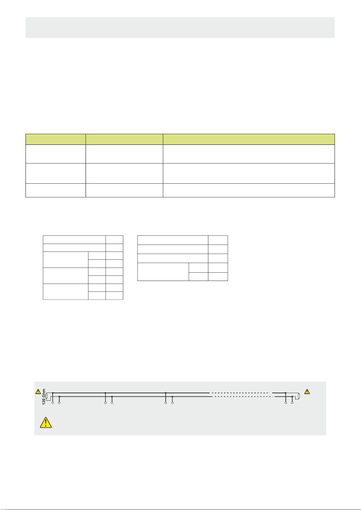
ENDA PID CONTROLLEREUPx420 SERIES TEMPERATURE
MODBUS PROTOCOL ADDRESS MAP
4.MODBUSERRORMESSAGES
Modbus protocol has two types error, communication error and operating error. Reason of the communication error is
data corruption in transmission. Parity and CRC control should be done to prevent communication error. Receiver side
checks parity and CRC of the data. If they are wrong, the message will be ignored. If format of the data is true but
function doesn’t perform for any reason, operating error occurs. Slave realizes error and sends error message. Most
significant bit of function is changed '1' to indicate error in error message by slave. Error code is sent in data section.
Masterrealizeserrortypeviathismessage.
Error Code Meaning
Name
ILLEGAL FUNCTION
ILLEGAL DATAADDRESS
ILLEGAL DATA VALUE
01
02
03
The function code received in the query is not an allowable action for the slave. If a
Poll Program Complete command was issued, this code indicates that no program
function preceded it.
The data address received in the query is not an allowable address for the slave.
A value contained in the query data field is not an allowable value for the slave.
Device Address
Function Code
Beginning address
of coils.
Number of coils (N)
CRC DATA
MSB
LSB
MSB
LSB
LSB
MSB
Structure of command message (Byte Format)
(0A)h
(01)h
(04)h
(A1)h
(00)h
(01)h
(AC)h
(63)h
Device Address
Function Code
CRC DATA
LSB
MSB
Structure of response message (Byte Format)
(0A)h
(81)h
(02)h
(B0)h
(53)h
Error Code
Message sample ;
As you see in command message, coil information of (4A1)h = 1185 is required but there isn’t any coil with 1185 address.
Thereforeerrorcodewithnumber(02)( )sends.IllegalData Address
ModBus Error Codes
* MODBUS CONNECTION DIAGRAM
120 Ohm
Master Slave - 1 Up to 127 slave devices
can be controlled.
Slave - 2 Slave - 127
A
BA
B
A
BA
B
Termination should be accomplished
by attaching 120 Ohm resistors to the
start and at the end of the
communicationline. * AppliestodeviceswithModbusfunction.
5. / 5
E-mail : info@suran-elektronik.de
Internet : www.suran-elektronik.de
Tel.: +49 (0)7451 / 625 617
Fax: +49 (0)7451 / 625 0650
SURAN Industrieelektronik
Dettinger Str. 9 / D-72160 Horb a.N
EUPx420-E-Modbus-03052019
Other manuals for ENDA EUP Series
1
Table of contents
Other SURAN Controllers manuals


Popular Controllers manuals by other brands


Sony
Sony BKSI-2440 Series installation manual

LEGRAND
LEGRAND 0 484 22 manual

Allen-Bradley
Allen-Bradley PowerFlex 400 installation instructions

Rain Bird
Rain Bird ESP-LXD troubleshooting guide

Innovative instruments
Innovative instruments AI-5481 User's operating manual

4IPNET
4IPNET WHG321 V3.30 Quick installation guide