SureShot AC2-GP User manual

AC2-GP
Multi-Sweetener Dispenser
D-19-123 RevA
Service Manual


AC2-GP
Multi-Sweetener Dispenser
FEATURES:
Easy to install –plug in, load, dispense
Easy refill and service
Accurate, preprogrammed, consistent
portions
Drink Count Data available
Clean dispense –quick cutoff avoids messy
spills
Dispenses two products
Feet are moveable to slide under
neighboring appliances
SureShot Technical Assistance Center
1-888-777-9990 or 902-865-9602
service@sureshotdispensing.com
parts@sureshotdispensing.com
www.sureshotdispensing.com
A.C. Dispensing Equipment Inc.
100 Dispensing Way
Lower Sackville, Nova Scotia
Canada B4C 4H2
TABLE OF CONTENTS
The Dispenser....................................................1
Main Components..............................................1
Specifications.....................................................1
Safety Precautions.............................................2
Operating Instructions........................................2
Service and Warranty.........................................2
Reshipment........................................................2
Troubleshooting .................................................3
Replacement Parts.........................................3
Remove and Install Components.......................8
Tools Required ...............................................8
Auger Motor....................................................8
Power Supply ...............................................11
Transition Pieces..........................................12
Repositioning or Replacing the Door............13
Door Cable Assembly...................................14
External Power Supply Connector PCB.......15
Power Entry Module and Harnesses............16
Replace Motor Cable Assemblies ................17
Reprogramming Using a FOB......................18
Accessing the Program....................................19
Appendix 1 .......................................................21
Assembly Diagram and Service Parts Lists .21
Appendix 2 .......................................................26
Wiring Diagram.............................................26

AC2-GP Multi-Sweetener •SureShot Technical Assistance Center: 1-888-777-9990 or 902-865-9602
1
AC2-GP
Dispenser may not be exactly as shown
MULTI-SWEETENER DISPENSER
SERVICE MANUAL
Important: Read this Manual now and retain it for future reference
THE DISPENSER
The SureShot Dispensing Systems® AC2-GP Multi-Sweetener Dispenser automatically
dispenses controlled portions of two dry products such as sugar and other alternative
products for use in coffee, milkshakes, hot chocolate, health drinks and other beverages.
The product is dispensed by touching selection buttons on the front of the dispenser.
The dispenser has been preconfigured to industry-standard defaults. Each button press
is preset independently to accurately dispense a specified amount of product using our
unique, state-of-the-art microprocessor technology. The products to dispense are
contained in product hoppers inside the dispenser. The auger style dispense system is
designed to work with dry products with similar consistency to sugar granules.
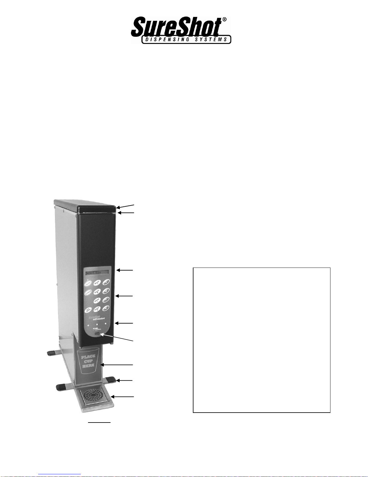
MAIN COMPONENTS
Program Mode Buttons
Program Mode
Adjustment Up
Adjustment Down
Panel Disable
LCD Display
Window
Button Panel
Infrared
Programming
Window
Program /
Maintenance
Mode Buttons
Catch Tray and
Screen
Cup Guide
(optional)
Dispenser Top
Transition Piece
(under top)
SPECIFICATIONS
Weight: 29.0 lbs/13.2 kg
(empty dispenser)
Dimensions (DxWxH): 17.75" x 4.0" x 24"
(without feet)
Dispenser height
varies with feet
selection
Hopper Capacity: Top Hopper
6.0 lbs/2.7 kg
(granular sugar)
Bottom Hopper
2.5 lbs/1.1 kg
(granular sugar)
Electrical Requirement: 100-240 VAC,
0.5 amps Max.
50-60Hz, 1 ph
Positionable
Feet

AC2-GP Multi-Sweetener •SureShot Technical Assistance Center: 1-888-777-9990 or 902-865-9602
2
SAFETY PRECAUTIONS
Always plug the dispenser into an approved electrical outlet.
The dispenser includes a microcontroller and must be operated on grounded
electrical wiring at all times.
Unless otherwise specified in the procedure, the dispenser should be unplugged from
its electrical source before servicing.
Do not immerse the dispenser in water.
Observe all safety precautions with this dispenser that you would with any electrical
appliance.
The dispense auger is powered by a motor with a turning shaft. To avoid possible
injury or equipment damage, keep hands and objects clear of the auger and shaft
when equipment is plugged in.
OPERATING INSTRUCTIONS
For all operating procedures and instructions refer to the operations manual specific to
the dispenser being serviced. For general operating instructions refer to manual D-19-
090.
SERVICE AND WARRANTY
Standard warranty is one year, on-site parts and labour (unless otherwise negotiated).
Access to USA and Canada-wide Technical Service Network.
The Warranty will be null and void if the dispenser is serviced by unqualified personnel.
Under warranty, service technicians must be approved and dispatched by the SureShot
Technical Assistance Center.
During the warrantee period, the SureShot Technical Assistance Center must be
contacted at 1-888-777-9990 or 902-865-9602 for approval of any proposed service
before commencing.
The customer is responsible for all costs not approved by SureShot Dispensing
Systems®.
Note: the Serial Number and Option Code of your dispenser are located on the Product
Identification Label on the back of the unit. Please refer to these numbers when
contacting the SureShot Technical Assistance Center. These numbers are crucial in
helping us provide prompt and effective service. This will save you time.
RESHIPMENT
No returns will be accepted without prior approval. Obtain a Return Materials
Authorization (RMA) number by contacting the SureShot Technical Assistance Center at
1-888-777-9990 or 902-865-9602.
Ensure pieces which may shift in transit are secured using masking tape.
If packaging is not available, it may be purchased from the SureShot Parts Department
by calling 1-888-777-9990 or 902-865-9602.

AC2-GP Multi-Sweetener •SureShot Technical Assistance Center: 1-888-777-9990 or 902-865-9602
3
TROUBLESHOOTING
The following trouble-shooting guide is intended to assist in tracking down some of the simpler
and/or more commonly occurring issues. Any actions or suggested replacement parts represent
possible causes and solutions only and are not guaranteed to correct the observed issue. If there
are any questions regarding either the procedures or the replacement parts required, please
contact the SureShot Technical Assistance Center at 1-888-777-9990 or 902-865-9602.
Replacement Parts
To determine replacement parts, refer to Appendix 1 on page 21.
Note: The Serial Number and Option Code of the unit must be included with the order
information for many of the replacement parts. Both are located on the Product
Identification Label on the back of the unit.
Problem
Action
Dispenser does not
turn on (LCD remains
blank after plugging in
the unit and none of
the buttons function).
The inability to turn on is an indication that either power is not reaching
the control circuit board in the door or the door itself is defective. Follow
through the steps described below to isolate the issue. Check unit
functionality after each step and repair defect or replace parts as
required.
1. Check to ensure that the wall outlet is functioning.
2. Check that all external power cord(s) are completely and securely
connected at all points.
3. On Units with an external power supply1:
a. Verify that the retaining nut on the power feed-through on the
back of the unit is fully installed. (If the nut has backed-off it may
prevent full connector engagement.)
b. Verify that the connection from the power cord to the jack on the
back of the unit is secure by trying to move the connector. If the
power comes on for any length of time then the connection is
poor. If the connector cannot be tightened further then the power
entry PCB may have to be replaced (see page 15).
c. Verify supply functionality –remove the power cord jack from the
back of the unit and using a volt-meter verify that there is 12 VDC
at the power supply by probing the connector jack. If 12 VDC is
present, re-connect to machine.
4. Check that the door cable is completely and securely connected to
the circuit board in the door. To do this:
a. Open the front door and remove door wire grommet
b. Gently tug on door cable to ensure secure connection.
5. With the unit powered on, verify power at door connector –open
door, remove door connector and confirm that voltage across pins 1
(or 2) and 4 (or 5) is 12 VDC. If there is power on the cable
connector but the door does not function when properly connected,
then the door may require replacement.
1
On units with Serial Number XXXX-003874 and lower the power supply is an external type as
shown on page 11. After that serial number the power supplies were installed inside the unit.

AC2-GP Multi-Sweetener •SureShot Technical Assistance Center: 1-888-777-9990 or 902-865-9602
4
Note: attachments to multi-meter probes may be required to access
connector contacts.
6. If there is no power at the door connector then trace back to where
the power is lost. To do this remove the right side panel (preferred) or
left side panel as viewed from the front of the unit.
7. On Units with an internal power supply:
Caution: the power supply and input connections are 110 VAC.
a. Ensure that all connections to the power supply and power entry
module are in place and secure.
b. Remove the input connector (with black and white wires) and
verify the voltage at the output of the wiring harness is 110 VAC.
If there is no voltage then either the power cord, the power entry
module or the power wire harness is defective and may need to
be replaced. Examine each further as required to find the
defective part.
c. Replace the power supply input connector and remove the output
connector on the top of the power supply. Check that the voltage
on the power supply output pins is 12 VDC. If the power is
present at the input but not at the output then the power supply
may need to be replaced.
- +
8. On Units with an external power supply:
a. Check the integrity of each connector and examine the wires for
breaks or other damage. If the integrity is unclear, replace with
new wire to see if problem is corrected. Replace as required.
b. Check the power availability of each connector in turn using the
diagram shown in step 5 as a guide. As can be seen with the
side panel removed, the wiring is a sequential series of wires
with RJ45 connectors at each end. A break in connection at any
point eliminates power (or communication) from propagating to
any points “downstream” of the break. Replace any damaged
wires or components as required.
Dispenser resets
intermittently (goes
through power-up
sequence)
The intermittent resetting of a unit is usually an indication of a faulty
connection somewhere between the power supply and the control PCB in
the door. To find the fault:

AC2-GP Multi-Sweetener •SureShot Technical Assistance Center: 1-888-777-9990 or 902-865-9602
5
1. Check all connections in line with door power (see “Dispenser does
not turn on” troubleshooting section above) and verify that they are
completely and securely connected. Repair or replace any defective
parts as required.
2. If all connections are secure and symptoms recur without any
connections being compromised then the issue is likely to be either a
faulty power supply or an intermittent connection on the PCB in the
door.
3. If possible, replace the power supply with one that is known to
function properly and verify that intermittency disappears. If it is still
present then the intermittency is likely in the door and the door may
need replacement (see Page 13).
Button panel “locks-up”
or functions
unpredictably
As the unit is controlled by a micro-controller it is possible that under
some conditions (such as power surges or brown-outs) that a part of the
program becomes corrupted. To correct this condition:
1. Reset the unit by unplugging and re-connecting power. If problem
persists then continue to next step.
2. If this is not the issue and the problem persists the unit should be re-
programmed using a FOB (see page 18).
3. If the problem is still not corrected then the issue is a likely to be a
defective PCB and the door may have to be replaced (see page 13).
LCD display is blank
(or all black squares)
but unit continues to
function normally
otherwise.
An LCD that does not display properly may be caused by either a
defective LCD module or a faulty program. To determine the likely cause:
1. Reset the unit by unplugging and re-connecting power. If the LCD
continues to show a blank including during the power-up sequence
(during Reset) then the LCD is defective and the door may need to
be replaced. If the LCD does display characters during the power-up
sequence but not once the reset is complete then continue to next
step.
2. Re-program the unit using a FOB to over-write the corrupted program
with a new one.
Unit dispenses
incorrect amount of
product.
There can be several causes for the unit to dispense incorrect amounts
of product. The following steps should be followed to diagnose and
correct this issue:
1. Ensure that unit is set up and being operated correctly:
a. Ensure that hopper contains adequate amount of product - the
hopper should be filled at least to the low level mark.
b. Ensure that the hopper is securely positioned in the unit and
properly engaged with the motor coupler (See Loading Hoppers
in Operational Manual)
c. Ensure all required selections have been made: Beverage Type,
Product Selection, Size etc.
d. Ensure that the dispense Target is set correctly (refer to
Operations Manual if required).
e. Ensure that the correct Product type has been selected in the
program (refer to Operations Manual if required).
f. Ensure that the Volume Adjust is correct. (The factory default is
zero but it may be altered to compensate for local variations of
the product - refer to Operations Manual if required).
g. Ensure that the product delivery tubes are not twisted, kinked,
pinched-off or blocked.

AC2-GP Multi-Sweetener •SureShot Technical Assistance Center: 1-888-777-9990 or 902-865-9602
6
2. Reset the unit by unplugging and re-connecting power.
3. Verify that the auger is clean and is able to move freely by removing
the hopper and manually rotating the auger.
4. Ensure that the motor coupler is securely attached to the motor shaft
by removing the hopper and twisting it. If the coupler is firmly
attached, the motor/gearbox can be heard and felt to rotate. If it is
loose it may rotate freely or pull off easily and should be corrected by
tightening the coupler attachment screw.
Note:. When installing or tightening a coupler, make sure that the
coupler is pushed back to the plastic spacer but not tight enough to
restrict the coupler from rotating freely.
Note: In newer models the coupler can only be installed with the
clamping screw parallel to the flat side of the shaft.
5. If the coupler does not rotate smoothly and freely then it is possible
that the motor/gearbox assembly is damaged and may need to be
replaced. To verify this, re-position the coupler by loosening and re-
tightening it as described in the note above. If the coupler is still
unable to turn then the motor assembly may have to be replaced.
6. Ensure that the motor is securely attached to the chassis by trying to
move the coupler side-to-side with the hopper removed. If it is loose,
tighten it and retest.
If the “Dispensing…” message persists for several seconds after the
dispense cycle has completed it is an indication that the rotary encoder
on the back of the motor assembly has become loose. To verify that this
is the problem:
7. Try dispensing several sizes of the same product. If the rotary
encoder is loose then all sizes will dispense approximately the same
amount of product. Also, the dispense cycle sounds different. Rather
then a sharp starting and stopping of the motor, the motor stops
slowly over a second or two at the end of dispense. In addition, in
units where the motors have a reverse rotation at the end of
dispense, the reverse portion of the dispense cycle is missing which
can be heard by the lack of the extra motor activation at the end of
each dispense.
8. Remove the left or right side cover and remove the hopper.
9. Holding the motor coupler with one hand, try moving the disk on the
rear of the motor shaft. It should only allow a small amount of rotation
before the coupler turns (the gearbox has a 10:1 ratio) and it should
not permit any axial movement on the shaft. See Figure 6 on page 9
for view of rotary encoder.
Note: Care should be taken not to disrupt the dipswitch on the motor
circuit card as any change in the dipswitch settings will cause the unit
to malfunction. The dipswitch is on the left hand side of the card (as
viewed from the front of the unit looking back) near the bottom of the
card. See page 9 for illustration of dipswitch.
If this examination is inconclusive the motor may need to be removed
for closer examination. If the rotary encoder is loose the motor
assembly will have to be replaced.

AC2-GP Multi-Sweetener •SureShot Technical Assistance Center: 1-888-777-9990 or 902-865-9602
7
Dispenser behaves
erratically… either:
1. opposite product
dispenses from the
one selected,
2. both products
dispense at same
time,
3. neither product
dispenses,
4. the same product
dispenses
regardless of
product selection,
or
5. unit continually
resets when
dispense button is
pressed.
If any or several of these symptoms appear after a motor replacement or
other service work has been performed it may be due to an incorrect
dipswitch setting on a motor driver circuit card (See Figure 6 on page 9).
The dipswitches are used by the controlling software to identify each
motor separately on the communication bus. To determine whether this
is the issue and to correct it:
1. Remove the left side panel (as viewed looking at the front of the unit).
2. Examine dipswitch settings (See Page 9 for setting details) and
confirm that they are correct according to the diagram.
3. If one or both are not set as shown in the diagram, correct using a
fine-tipped object such as a ball point pen. Once reset the unit must
be re-booted by powering down / up again.
4. If the problem persists, the motor driver program may have been
corrupted. Re-program the driver using ‘Driver DL Force’ as
described on page 19.
5. If the problem persists it is possible that the dipswitch itself is
defective. To help identify this situation, change the dipswitch setting
on one of the motor assemblies to an unrecognized address by
toggling switch 3 or 4 to the “on” position. This makes sure that the
motor will not respond to any dispense signals and leave the other
motor free to respond normally without interference from the first
motor. If this corrects the issue then the first motor assembly may be
defective and may need to be replaced.
Dispenser accumulates
product inside the unit.
An accumulation of product inside the unit around the bottom of either
hopper can be caused by several things. To identify the cause and to
correct:
1. If the unit is a “Fill-in-Place” unit (with removable top cover), verify
that the transition piece (see Appendix 1) on the top of the unit is
present and seated properly. This part forms a funnel to direct the
product into the top hopper. If not present, product can leak past the
hopper to the inside of the unit. Replace or reposition if required.
2. Check the product delivery tubes for any breaks and for proper
attachment to the hoppers. Re-attach or replace if required.
If the product accumulation is around the back of the hopper (around the
motor coupler) it may be an indication that the auger shaft or auger
bushing is worn, enabling product to leak out the rear of the hopper. To
confirm this diagnosis and to correct the issue:
3. Remove the hopper assembly and examine the fit of the auger in the
rear of the hopper assembly. It should be snug with no sideways play
in the bushing. If sideways play is present then the auger assembly
may have to be replaced.
Button panel “locks-up”
(LCD is ON but none of
the buttons function)
The dispenser is controlled by a micro-controller and may be subject to
temporary disruption by some types of power anomalies. If the button
panel “locks-up” it is an indication that the micro-controller operation has
been corrupted. If this happens all functions stop working. To correct this
issue:
1. Unplug the dispenser, wait 10 seconds, then plug the dispenser back
in. This resets the microcontroller.
2. If this does not correct the issue then the program itself may have
become corrupted and the unit may have to be re-programmed using
a FOB (See page 18).

AC2-GP Multi-Sweetener •SureShot Technical Assistance Center: 1-888-777-9990 or 902-865-9602
8
The auger motor does
not respond to
dispense commands
(no sound or sign of
movement)
The motor is controlled by a software program running on a micro-
controller in the motor assembly which in turn is controlled by a micro-
controller and software in the door. A non-responsive auger motor can be
an indication of several things. To determine the likely cause of the issue
and to correct it:
1. Remove the hopper assembly and try rotating the coupler by hand. If
the coupler either does not rotate at all or requires excessive force
then it is likely that the motor assembly has seized and may need
replacement (see page 9).
2. If the auger coupler rotates freely then it is possible (although
unlikely) that the motor driver software has become corrupted. A
copy of the driver software, however, is kept in the door software and
can be downloaded to the motor driver chip to correct this issue. To
do this follow the Program Mode > Service Page > Driver DL Force
instructions on page 19.
3. If the issue persists after successfully re-loading the driver software
then the connections and wires between the door and the motor
assembly should be checked for signs of damage. Any suspect wires
should be checked by installing new wires and replaced as required.
4. If the problem persists then the dipswitch setting should be checked
(see page 9 for description of correct settings)
5. If the problem still persists then it is likely that the motor assembly
itself is damaged and may have to be replaced.
Door does not stay
closed
The door latches when the door latch screw on the top of the door
opposite the hinge snaps into the latching hole in the top plate. If the
screw is missing or the top plate becomes bent then the latch will not
work properly.
1. Check to see if the latching screw on the top right hand side of the
door is present and secure. Correct as required.
2. If the screw is present and secure and the door still does not latch
properly, adjust the top plate position by carefully bending up or
down as required. When located correctly, the hole in the top plate
should hold the latching screw firmly when the door is closed but
allow the door to open and close with comfortable ease.
REMOVE AND INSTALL COMPONENTS
Tools Required
All service procedures can be performed with a minimum of tools as follows:
Medium sized Phillips screwdriver
Small sized Phillips screwdriver
5/16" wrench
10mm wrench
3/32" Allen wrench
7/64” Allen wrench
9/64" Allen wrench
Multi-meter
Power Drill
Rivet Gun
Figure 1
AC2-GP Multi-Sweetener •SureShot Technical Assistance Center: 1-888-777-9990 or 902-865-9602
9
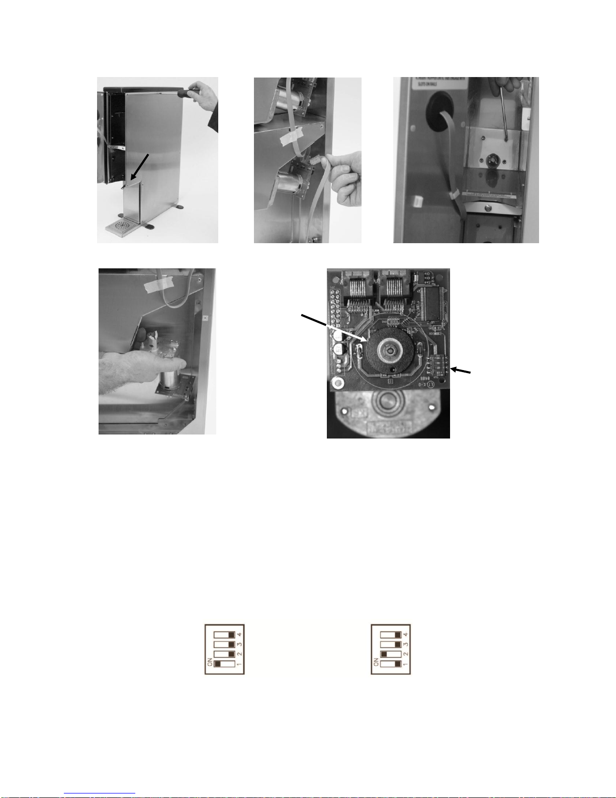
Auger Motor
Figure 2
Figure 3
Figure 4
Figure 5
Figure 6
Removal:
1. Unplug power cable from power outlet or from rear of dispenser.
2. Remove the hopper connected to the motor being replaced.
3. Remove either side panel using Phillips screwdriver to remove all the screws holding the
side panel on. See Figure 2
4. Unplug the motor connector cables from the back of motor assembly being replaced. See
Figure 3.
5. From the inside of the hopper compartment, remove the four 8-32 screws holding the
motor in position, using a 9/64”Allen key. See Figure 4.
6. Remove the motor assembly. See Figure 5.
7. Before installing the new motor assembly, make sure that the dipswitches are set
correctly as indicated below:
Upper Motor Dipswitch Setting Lower Motor Dipswitch Setting
Note: The dipswitch settings are shown as viewed in Figure 6.
Rotary
Encoder
Dipswitches
Short
Screw

AC2-GP Multi-Sweetener •SureShot Technical Assistance Center: 1-888-777-9990 or 902-865-9602
10
Installation:
8. Replace the motor assembly by installing the four 8-32 screws.
Note: It is recommended that thread-locker be used on these screws when replacing them.
9. Plug connector cables back into the connectors located on motor PCB. Care should be
taken to ensure that the right cables are re-attached to prevent over-stretching the wires.
10. Install the side panel.
Note: Short screw located in lower- front location as indicated in Figure 2.
11. Install hopper
12. Plug power cable back into unit.

AC2-GP Multi-Sweetener •SureShot Technical Assistance Center: 1-888-777-9990 or 902-865-9602
11
Power Supply
Early models of the AC2-GP (Serial Numbers XXXX-003874 and earlier) were equipped with an
external power supply as shown in Figure 7 below. Later models have the power supply mounted
inside the unit on the lower part of the back panel. To replace the power supply follow the
directions for the type being serviced.
External Power Supply:
Figure 7
Removal:
1. Unplug the power supply from the wall and disconnect from the back of the unit.
Installation:
1. Ensure that all cords are completely and securely connected together.
2. Plug the cord connecting the power supply to the dispenser into the back of the dispenser
and fully tighten the screw-lock.
3. Plug the other cord from the power supply into the wall outlet.
Internal Power Supply:
Figure 8
Removal:
1. Unplug power cable from power outlet or from rear of dispenser.
2. Remove either the left or the right side panels from the unit.
3. Unplug the input and output connectors from the power supply.
4. Unscrew the four corner screws using the small sized Phillips screwdriver.
Installation:
5. Hold the new power supply into place and install the bottom two screws.
6. Install each of the upper screws ensuring to replace grounding lugs, one under the head
of each mounting screw.
7. Plug the output (12 VDC) and input (110 VAC) connectors into the top and bottom of the
power supply respectively.
8. Replace the side panel –make sure to replace the short screw in the correct location
(see Figure 2 on page 9).
9. Plug power cable into outlet.

AC2-GP Multi-Sweetener •SureShot Technical Assistance Center: 1-888-777-9990 or 902-865-9602
12
Transition Pieces
Figure 9
Figure 10
Figure 11
Figure 12
Removal:
1. Remove the plastic top lifting it up and off. See Figure 9
2. Remove the plastic transition piece by lifting it up and out of the stainless steel transition.
See Figure 10
3. Remove the screws holding on the Stainless steel transition using a Phillips screw driver.
See Figure 11
4. Lift off the Stainless steel transition by lifting it up and off. See Figure 12
Installation:
5. Install new Stainless steel transition over the side panels and install screws. Make sure to
install the short screw in the location indicated.
6. Replace plastic parts onto unit.
Short
Screw

AC2-GP Multi-Sweetener •SureShot Technical Assistance Center: 1-888-777-9990 or 902-865-9602
13
Repositioning or Replacing the Door
Figure 13
Figure 14
Figure 15
Figure 16
Figure 17
Figure 18
Removal:
1. Open the dispenser door fully (180°). See Figure 13.
2. Remove door cable from clamp and pop out the black grommet from the door. See
Figure 13
3. Unplug the door cable from behind the grommet.
4. Lift the top off the dispenser.
5. Remove the fastener from the top of the door, using a 3/32 Allen key. See Figure 14.
Hold onto door when removing fastener. See Figure 15.Retain fastener for installation.
Steps 6 to 11 Optional for door swing direction
6. If repositioning door hinge to swing in opposite direction, remove the screw in the cable
locator plate. See Figure 16.
7. Remove Phillips screw from top of door using Phillips screw driver. See Figure 17.
8. Remove hinge standoff from bottom of door using 5/15" wrench. See Figure 17.
9. Remove the 2 grommets from chassis. See Figure 17.
10. Install all the removed fasteners and hardware on the opposite side from which they were
removed.
11. Flip cable and locator plate to position cable on opposite side of chassis. See Figure 18.
Installation:
12. Install the new door with fastener. See Figure 18
13. Plug in the cable removed and replace the grommet. See Figure 18
14. Close door.

AC2-GP Multi-Sweetener •SureShot Technical Assistance Center: 1-888-777-9990 or 902-865-9602
14
Door Cable Assembly
Figure 19
Figure 20
Figure 21
Figure 22
Figure 23
Figure 24
Removal:
1. Unplug power cable from power outlet or from rear of dispenser See Figure 19
2. Remove top hopper to make access to cable locator easier. See Figure 20
3. Remove left side panel by using a Phillips screwdriver to remove all the screws holding
the side panel on. See Figure 21
4. Unplug the door cable connector from the back of top motor assembly located closest to
left hand side. See Figure 22
5. Remove the cable from the cable clamp located under the upper hopper compartment.
See Figure 22
6. Remove door cable from clamp and pop out the black grommet from the door. See
Figure 23
7. Unplug the door cable from behind the grommet. See Figure 23
8. Remove the cable locator screw using Phillips screw driver. See Figure 23.Retain
screw for replacement cable assembly.
9. Remove the door cable assembly though the front of the unit. See Figure 24
Installation:
10. Reverse the sequence to install the replacement cable assembly.
Note: Make sure cable connector with grommet end is out when replacing new cable.
Note: Short screw located at front in lower hopper location. (See Figure 2 on page 9).
11. Plug power cable into outlet.

AC2-GP Multi-Sweetener •SureShot Technical Assistance Center: 1-888-777-9990 or 902-865-9602
15
External Power Supply Connector PCB
(For units with external power supplies only)
Figure 25
Figure 26
Figure 27
Figure 28
Figure 29
Figure 30
Removal:
1. Unplug power cable from power outlet or from rear of dispenser. See Figure 25
2. Remove either side panel by using a Phillips screwdriver to remove all the screws holding
the side panel on. See Figure 26
3. Disconnect the cable from the power supply PCB assembly. See Figure 27
4. Remove nut from connector at rear of dispenser using a 10mm wrench. See Figure 28
5. Remove the power supply PCB assembly by gently pulling to detach the mounting tape
from the frame. See Figure 29.
Installation:
6. Remove retaining nut and adhesive protective backing on new power supply assembly
and position into frame.
7. Replace the nut onto new connector.
8. Connect the cable to the power supply assembly.
9. Position the side panel onto the frame and replace screws.
Note: Short screw located at front in lower hopper location (See Figure 2 on page 9).
10. Reconnect power supply.
11. Plug power cable into outlet.
AC2-GP Multi-Sweetener •SureShot Technical Assistance Center: 1-888-777-9990 or 902-865-9602
16
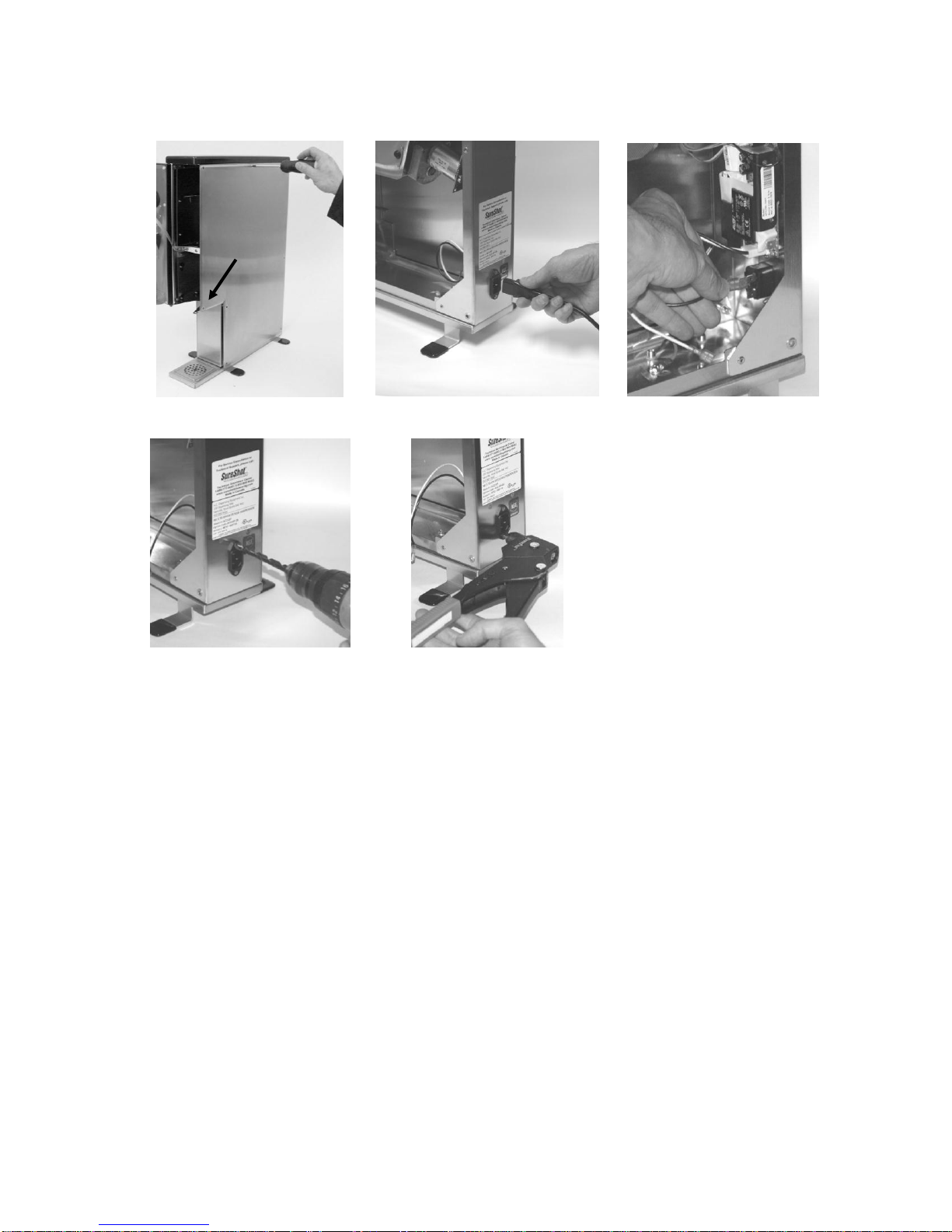
Power Entry Module and Harnesses
(For units with internal power supplies only)
Figure 31
Figure 32
Figure 33
Figure 34
Figure 35
Removal:
1. Unplug unit from the wall.
2. Remove either side panel by using a Phillips screwdriver to remove all the screws holding
the side panel on. See Figure 31
3. Unplug the power cord from the unit. See Figure 32.
4. Disconnect the wiring harness connectors from the power entry module (and from the
power supply if the harness is being replaced). See Figure 33.
5. Remove the power entry module by drilling out the fastening rivets from the rear of the
unit. Pliers may be needed to hold the end of the rivet on the inside of the unit to prevent
it from rotating. See Figure 34.
Installation:
6. Rivet a new power entry module into place using 1/8” diameter, domed, stainless steel
pop rivets with a 0.18” grip. Ensure to install the module in orientation as shown to avoid
confusing the wire connections.
Note: Alternatively, the power entry module can be installed using 4-40 stainless
machine screws with a nut and washer on the inside.
7. Replace the power wiring harness and ground wire.
8. Position the side panel onto the frame and replace screws. Make sure to install the short
screw in the location indicated.
9. Plug power cable into back of unit and into outlet.
Short
Screw
Other manuals for AC2-GP
1
Table of contents
Other SureShot Beverage Dispenser manuals


Popular Beverage Dispenser manuals by other brands

La Sommeliere
La Sommeliere DVV22 manual

MICROMATIC
MICROMATIC INLINE MININIM User manual & installation guide

lancer
lancer Sensation 30 installation guide

Bunn
Bunn FMD-1 Specifications

Flavor Burst
Flavor Burst Dual Series Operation manual supplement

lancer
lancer BEVARIETY MCY-22 Installation and service manual


