Surface Concept Economy Series User manual

HVPS Economy Series - Manual
High Voltage Power Supply
Economy Series
(Release 041)
Manual
1

HVPS Economy Series - Manual
All rights reserved. No part of this manual may be
reproduced without the prior permission of
Surface Concept GmbH.
Surface Concept GmbH
m Sägewerk 23a
55124 Mainz
Germany
Tel. ++49 6131 627160
Fax: ++49 6131 6271629
www.surface-concept.com,
User manual for the High Voltage Power Supply
Economy Series (Release 041).
Manual Version: 1.0
Printed on: 02.11.2017
2

HVPS Economy Series - Manual
1 Table of Contents
1 Table of Contents................................................................................................................................................................................... 3
2 Introduction............................................................................................................................................................................................... 4
2.1 General Information........................................................................................................................................................................ 4
2.2 Safety Instructions.......................................................................................................................................................................... 4
2.3 General Overview............................................................................................................................................................................. 5
3 Installation................................................................................................................................................................................................. 6
3.1 Initial Inspection................................................................................................................................................................................ 6
3.2 Installation........................................................................................................................................................................................... 6
4 Device Layout & Operation................................................................................................................................................................. 8
4.1 Device Layout.................................................................................................................................................................................... 8
4.2 General Device Operation............................................................................................................................................................ 9
4.3 Floating Operation on an external potential...................................................................................................................... 10
4.4 Schematic layout of the HVPS Eco........................................................................................................................................ 11
5 dditional Device Options................................................................................................................................................................ 12
5.1 Special Function Check.............................................................................................................................................................. 12
5.2 Contact Surface Concept.......................................................................................................................................................... 13
6 Error states........................................................................................................................................................................................... 14
7 Technical Data...................................................................................................................................................................................... 15
8 List of Figure.......................................................................................................................................................................................... 16
3

HVPS Economy Series - Manual
Introduction
.1 General Information
This manual is intended to assist users in the installation, operation and maintenance of Release Version 041
of the High Voltage Power Supply Economy Series (HVPS Eco). It is divided into 8 chapters.
. Safety Instructions
Please read this manual carefully before performing any electrical or electronic operations and strictly follow
the safety rules given within this manual.
The following symbols appear throughout the manual:
The “note symbol” marks text passages that contain important information/hints about
the operation of the device. Follow this information to ensure a proper operation of the
device.
The “caution symbol” marks warnings, which are given to prevent an accidentally
damaging of the device. Do NOT ignore these warnings and follow them strictly.
Otherwise no guarantee is given for arose damages.
The “high voltage symbol” marks warnings, given in context with the description of the
operation/use of high voltage supplies and/or high voltage carrying parts.
Hazardous voltages are present that can cause serious or fatal injuries. Therefore only
persons with the appropriate training are allowed to carry out the installation,
adjustment and repair work.
4

HVPS Economy Series - Manual
.3 General Overview
The Surface Concept HVPS Eco is a HV supply in a stand-alone housing with up to 4 independent HV channels.
Each channel holds two SHV connectors, which allow to select the polarity of the output voltage of each
channel individually by connecting either to the one or to the other output channel.
The device can produce lethal high voltages of up to several kV. Hazardous voltages are
present, therefore only persons with the appropriate training are allowed to carry out
the installation, adjustment and repair work.
Do not open the power supply, while it is in operation. Hazardous voltages are present.
In case that the device must be opened, turn off the device first AND pull out the power
plug.
5

HVPS Economy Series - Manual
3 Installation
3.1 Initial Inspection
Visual inspection of the system is required to ensure that no damage has occurred during shipping. If there
are any signs of damage, please contact SURF CE CONCEPT immediately. Please check the delivery
according to the packing list (see Table 1) for completeness.
1x High Voltage Power Supply Economy Series Release 041
1x BNC termination plug
1 – 4x SHV termination plug (depending on specific device layout)
Table 1: Packing list for the HVPS Eco
3. Installation
The general connection scheme of the HVPS Eco is shown in 4.3.
Finish the complete cabling before switching on the HVPS Eco and switch off the device
first before performing any changes to the cabling.
Figure 1: Exemplary cabling of the HVPS Eco for the use of the positive output polarity of CH 1.
6

HVPS Economy Series - Manual
Figure : Exemplary cabling of the HVPS Eco for the use of the negative output polarity of CH 1.
First, use the "
Ground”
connector (M4 screw) to ground the device.
High voltage output for each channel CH 1 to CH 4 (number of channels is device dependent), is
provided selectively to the SHV socket named
“HV +”
or
“HV -”
. The naming corresponds to the
polarity of the output voltage in respect to the ground potential.
Only one output polarity per channel can be used at one time. The connector for the other
output polarity is used to define the reference potential for the corresponding output channel
(see 4.3 for details).
Use the SHV termination plug to terminate the connector for the unused output polarity (+) or (-) to
ground or to an external reference voltage (for floating operation, see section 4.3)
In cases that no external reference voltage is applied to the device, the termination plug
must be used to ground the socket of the unused output polarity
“HV ”
or
“HV -”
(reference
potential of the corresponding channel). With a missing reference potential the HVPS Eco
module is not providing any output voltage.
Connect the power cable to the main connector.
Check if the Interlock-Plug (BNC termination plug) is connected.
7

HVPS Economy Series - Manual
4 Device Layout & Operation
4.1 Device Layout
The layout of the HVPS Eco is given below in Figure 3:
Figure 3: Layout of the HVPS Eco
1. Hardware reset button
2. Status LEDs for Power (lightens up
when device is switched on) and
Ethernet connection (lightens up
only when a software is connected
to the HV supply).
3. Touch Display
4. Control knob for high voltage
adjustment
5. Control knob for channel selection
6. Power switch, to turn ON/OFF the
device (lighted, when switched ON)
7. SHV connectors for output
voltages with positive (“
HV+”
) and
negative (“
HV-”
) polarity for channel
1 (“
CH 1”
).
8. SHV connectors for output
voltages with positive (“
HV+”
) and
negative (“
HV-”
) polarity for channel
2 (“
CH 2”
).
( vailability dependent on specific
device layout.)
9. SHV connectors for output
voltages with positive (“
HV+”
) and
negative (“
HV-”
) polarity for channel
3 (“
CH 3”
).
( vailability dependent on specific
device layout)
8
HVPS Economy Series - Manual
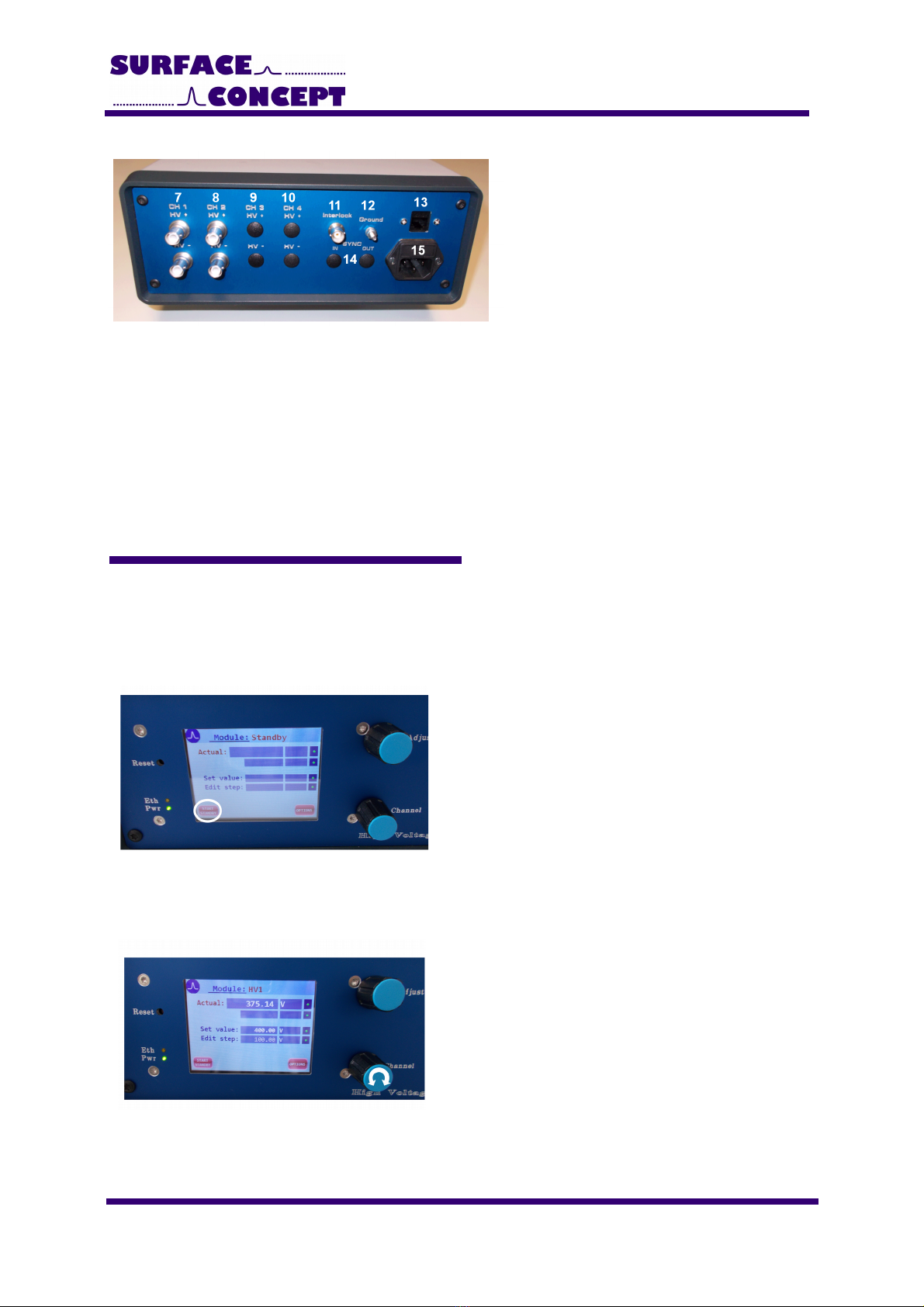
Figure 4: Layout of the HVPS Eco
10. SHV connectors for output voltages
with positive (“
HV+”
) and negative
(“
HV-”
) polarity for channel 4 (“
CH
4”
).
( vailability dependent on specific
device layout)
11. BNC connector for hardware
interlock (output of BNC connector
must be grounded to deactivate
interlock)
12. Ground connector for device
grounding
13. Ethernet Socket
14. BNC sockets for device
synchronization (availability
dependent on specific device layout)
15. Power socket
4. General Device Operation
fter switching on the device (14), the display (3) shows the “Surface Concept” animated logo, while the
device is scanning for internal available HV modules and their specific settings. This can take up to several
seconds. If the device is ready for operation, it switches into the standby mode and shows an empty mask for
the voltage adjustment (see Figure 8).
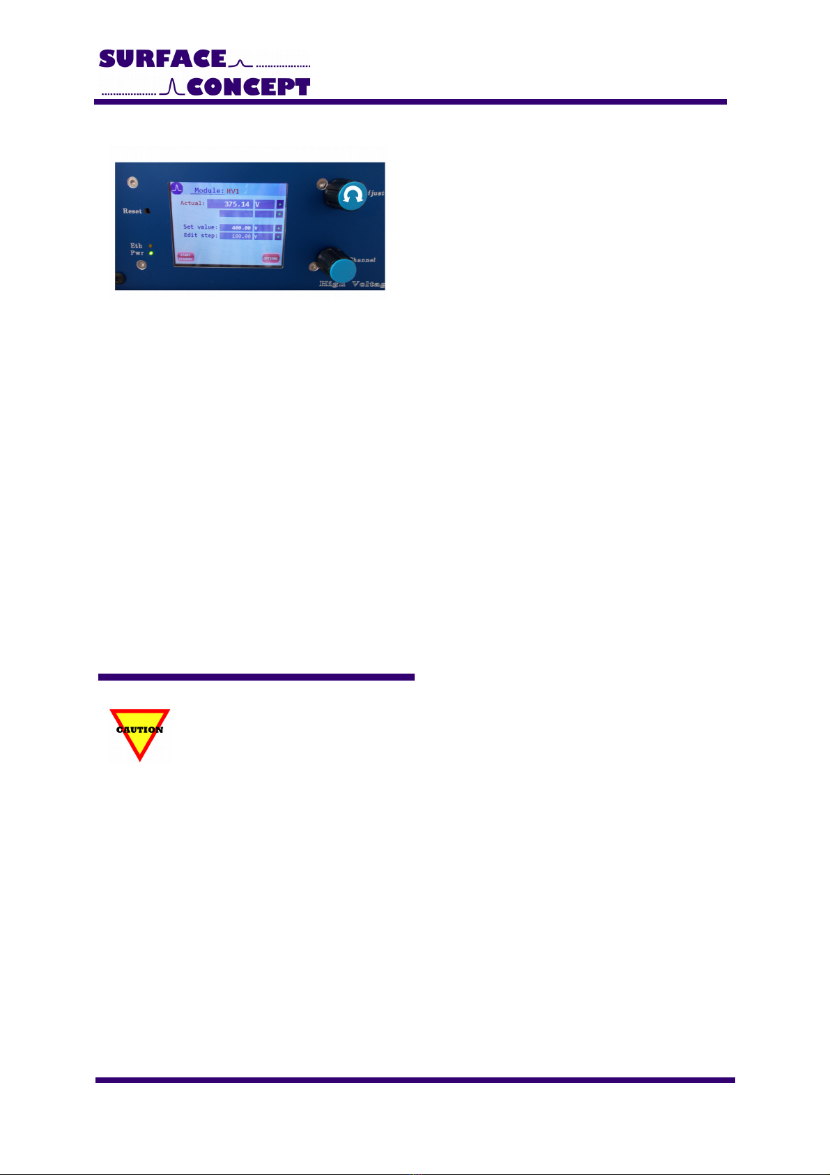
Figure 5: Standby mode
Push the “Start/Standby” button in the lower left
corner of the display to switch on the high voltage.
lternatively one can press the “Channel” control
knob.
Figure 6: Operation mode
fter switching on the high voltage the device is in
the so called operation mode. In operation mode the
display shows the name of the selected channel in
the top line (in this case “HV 1”) as well as the output
voltage of that channel.
The different HV channels can be selected by turning
the “Channel” control knob (R033 & R036 only).
9
HVPS Economy Series - Manual
Figure 7: Operation mode – voltage adjustment
The “ djust” control knob is used to adjust the
output voltage.
Turn the “ djust” control knob
clockwise/counterclockwise to increase/
decrease the value of the output voltage in a step
width as defined in the line “edit step”.
The line “set value” displays the nominal value for
the output voltage as adjusted by the user. Voltage
adjustment can only be made in this line.
The line “actual” displays the actual value for the
output voltage on the output connector as
measured by the device.
The device always regulates the actual value of the
output voltage to fit to the nominal value as set by
the user.
Hereby the voltage measurement is always a
relative measurement between the two HV outputs
of one channel. dditional reference voltages (e.g.
in floating operation) are not measured and
therefore are also not displayed (see chapter 4.3
for further details)
Turn the “ djust” control knob
clockwise/counterclockwise while pushing it to
increase/ decrease the step width in the line “edit
step”.
Push the “Start/Standby”-button in the lower left corner of the display again to switch back to the “Standby”
mode.
4.3 Floating Operation on an external potential
The HVPS is specified for the floating operation on an external reference voltage of
maximum +/- 1000 V. Higher voltages can lead to internal HV sparking and to a damage
of the device.
pplication case 1: Channel 1 should be set to an output voltage of +1000 V floating on an external reference
potential of –500 V. In this case the external reference voltage is connected to the connector of the negative
polarity of channel 1 (
“HV -”
). First set the output voltage of Channel 1 to +1000 V. Then increase the external
reference voltage to the -500V. The display shows a value of CH 1 = 1000 V, but the output voltage in
respect to the ground potential is CH 1 = +500 V. The output voltage of +500V is given out on connector
“HV +”
of channel 1.
pplication case 2: Channel 1 should be set to an output voltage of -500 V floating on an external reference
potential of +1000 V. In this case the external reference voltage is connected to the connector of the positive
polarity of channel 1 (
“HV +”
). First set the output voltage of Channel 1 to -500 V. Then increase the external
reference voltage to the +1000V. The display shows a value of CH 1 = 500 V, but the output voltage in
respect to the ground potential is CH 1 = +500 V. The output voltage of +500V is given out on connector
“HV -”
of channel 1.
10
HVPS Economy Series - Manual
4.4 Schematic layout of the HVPS Eco
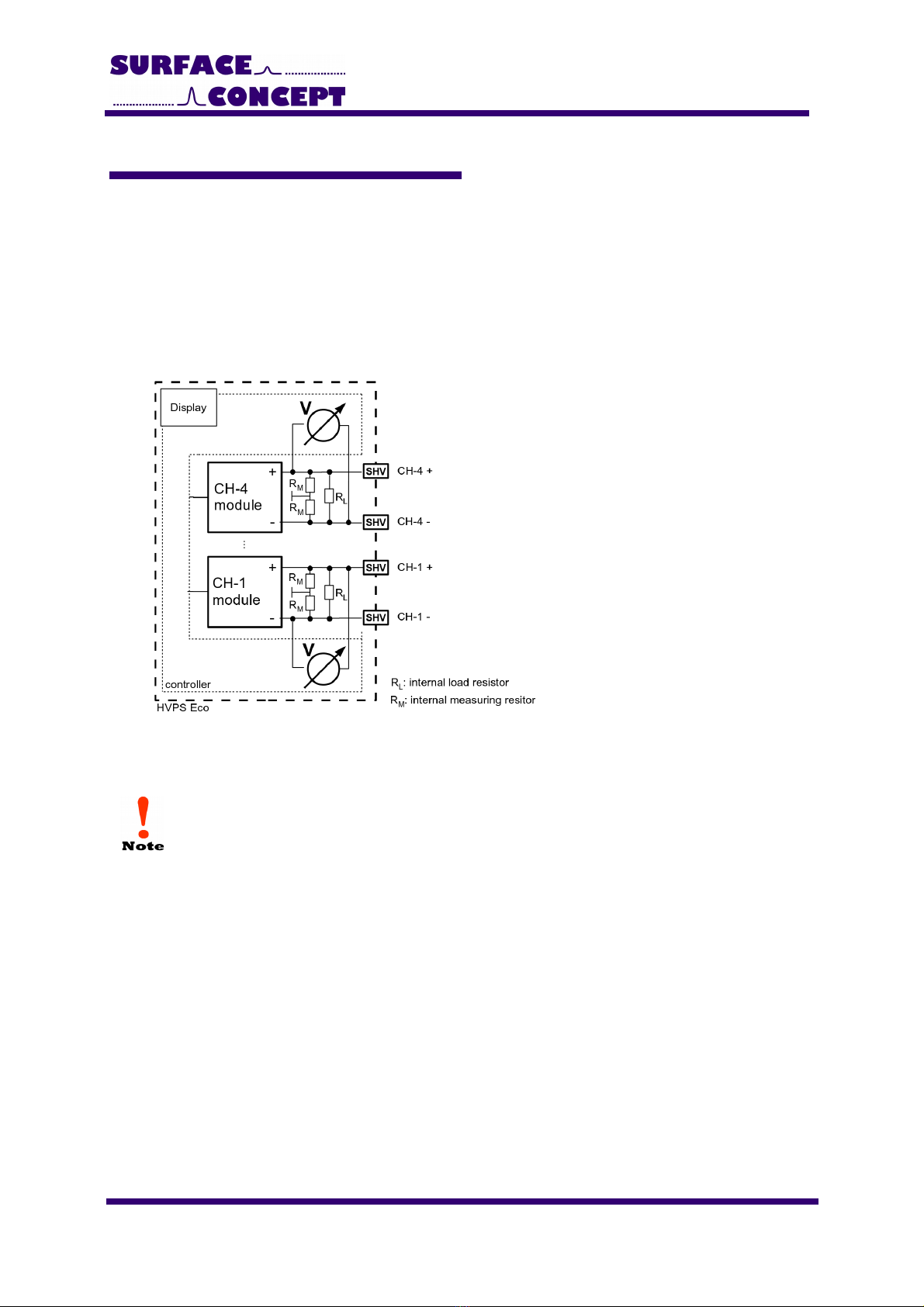
Figure 8 shows the schematic layout of the HVPS Eco and especially the layout of the HV outputs. n internal
controller measures the output voltage and regulates it to the nominal value entered by the user or set as
default value within the device. Hereby the voltage measurement is always a relative measurement. The
output polarity is defined by determine one of the outputs as reference potential (e.g. by termination to
ground). Voltage measurement and regulating is also only respecting the relative output voltage of the single
HV module in case of a floating operation. The absolute output voltage (as result of output voltage and
reference voltage) is not determined by the device. Figure 8 also shows the internal load and measuring
resistors. The specific values for the load and measuring resistors are given in the specification sheet.
Figure 8: Schematic layout of the HVPS Eco showing also the internal load and measuring resistors.
The single channels of the HVPS Eco are not producing any output voltage if the socket of
the unused output polarity (reference potential of the corresponding channel) is not
terminated (either to ground or to an external HV potential), because the HV modules
always need to be connected to a reference potential. A SHV termination plug for each
channel is part of the delivery.
11

HVPS Economy Series - Manual
5 Additional Device Options
Pressing the “Option” button in the lower right corner of the device display, the device will switch to the
overview display of the additional device options. The available options are device depending. Press the “Exit”
button to switch back to the display of the operation voltages.
Figure 9: “Device Options” sub-menu
The overview of the device options show the different
available options like the contact page for surface
concept or special device specific functions.
Open the specific sub-menu by pressing the
corresponding button in the touch display.
5.1 Special Function Check
The sub-menu “Special Function Check” in the device options display the different special functions currently
available for the Surface Concept HVPS D Series.
Not all listed functions are available for each single device layout.
Figure 10: “Special Functions Check” sub-menu
The “HV Master Tracking” allows the HVPS to track
an external reference voltage and to produce an
output voltage which is in a fixed defined relation to
the master voltage.
Please note: This function differs from the floating
functionality, because the master voltage is “only”
measured within the device and the HVPS is
producing a corresponding output voltage.
The “HV Master Tracking” can be switched ON/ OFF
by clicking on the corresponding button on the display
(not available for the R033 – R036).
12

HVPS Economy Series - Manual
5. Contact Surface Concept
The sub-menu “Contact Surface Concept” in the device options displays the Surface Concept contact
information. Press the “Exit” button to leave this sub-menu.
Figure 11: “Contact Surface Concept” sub-menu.
13

HVPS Economy Series - Manual
6 Error states
Error states of the device are indicated by error messages in the display.
Figure 1 : Error code – Interlock.
Err – Interlock
The device interlock is active and is blocking the HV
output.
Please terminate the interlock to ground using either
the BNC termination plug (part of the delivery) or
check the proper functionality of the use device which
is providing the interlock.
14

HVPS Economy Series - Manual
7 Technical Data
High Voltage Power Supply Eco Series
HV Output Channels: 1 – 4 (number of output channels are device dependent)
HV Output Connector: SHV5
Output voltage range (channel CH-1 to CH-4): see specification sheet
Output Polarity: see specification sheet
Input Connector for Reference Input : SHV5
Maximum Voltage for external reference potential: +/- 1000 V
Line Input
Electrical Input (LINE): 230 V, 50 Hz
Power: 65 Watt (max.)
Fuse: 1x T 1.6
15

HVPS Economy Series - Manual
8 List of Figure
Figure 1: Exemplary cabling of the HVPS Eco for the use of the positive output polarity of CH 1...............................6
Figure 2: Exemplary cabling of the HVPS Eco for the use of the negative output polarity of CH 1.............................7
Figure 3: Layout of the HVPS Eco........................................................................................................................................................... 8
Figure 4: Layout of the HVPS Eco........................................................................................................................................................... 9
Figure 5: Standby mode.............................................................................................................................................................................. 9
Figure 6: Operation mode........................................................................................................................................................................... 9
Figure 7: Operation mode – voltage adjustment........................................................................................................................... 10
Figure 8: Schematic layout of the HVPS Eco showing also the internal load and measuring resistors................11
Figure 9: “Device Options” sub-menu.................................................................................................................................................. 12
Figure 10: “Special Functions Check” sub-menu........................................................................................................................... 12
Figure 11: “Contact Surface Concept” sub-menu......................................................................................................................... 13
Figure 12: Error code – Interlock........................................................................................................................................................ 14
16

HVPS Economy Series - Manual
EU Declaration of Conformity
Manufacturer Surface Concept GmbH
m Sägewerk 23a
D - 55124 Mainz
Germany
Product: High Voltage Power Supply
Model: HVPS Eco
The above named products comply with the following European directive:
89/336/EEC Electromagnetic Compability Directive, amended by 91/263/ EEC and
92/31/ EEC and 93/68/EEC
73/23/EEC Low Voltage Equipment Directive, amended by 93/68/EEC
The compliance of the above named product to which this declaration relates is in
conformity with the following standards or other normative documents where relevant:
EN 61000-6-2:2005+ C:2005 Electromagnetic compatibility (EMC):
Generic standards - Immunity for industrial environments
EN 61000-6-4:2007+ 1:2011 Electromagnetic compatibility (EMC):
Generic standards - Emission standard for industrial
environments
EN 61010-1: 2010 Safety Requirements for Electrical Equipment for
Measurement, Control and Laboratory Use
For and on behalf of Surface Concept GmbH
Mainz,……01.04.2013………. Legal signature………………………………………….
(Date) (Dr. ndreas Oelsner)
This declaration does not represent a commitment to features or capabilities of the instrument.
The safety notes and regulations given in the product related documentation must be observed at
all times.
17
Table of contents
Popular Power Supply manuals by other brands


Nortel
Nortel UPS45 instruction manual

RFL Electronics
RFL Electronics RFL 9110 24DCPS instruction data

GAMDIAS
GAMDIAS KRATOS M1-600B Quick installation guide

SEW-Eurodrive
SEW-Eurodrive MOVITRANS THM20C operating instructions

Rohde & Schwarz
Rohde & Schwarz HM7042-5 manual

ACDC Dynamics
ACDC Dynamics CPS-150B user manual